ADA-WA 1; ADA-WA 4
5
ba76071e01 02/2012
Overview of the recommended installation locations (continued)
Sensor type Installation
location
(see diagram
on page 3)
Advantages (+) /
Disadvantages (-)
Conclusion / Comments
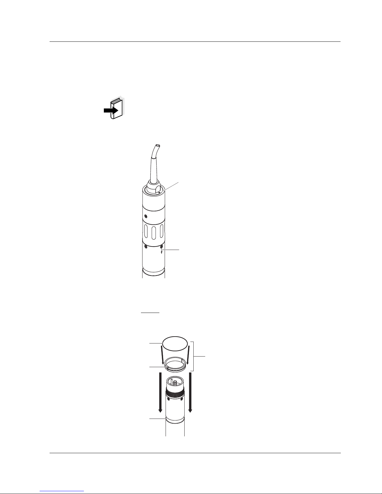
VisoTurb 700 IQ,
ViSolid 700 IQ
Note:
Please note the
special installation
recommendations
in the following
section.
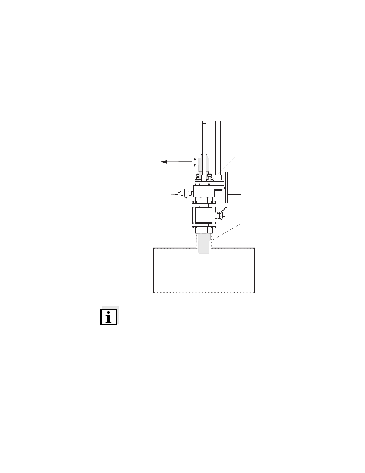
A + Optimum flow of the sapphire disc
so there is no capture of air bub-
bles or large particles in front of
the sensor
- Susceptible to fibers getting
caught
- Risk of damage from stones and
abrasive particles
Optimum installation location
for measuring media without
contamination from fibers,
stones, or abrasive particles.
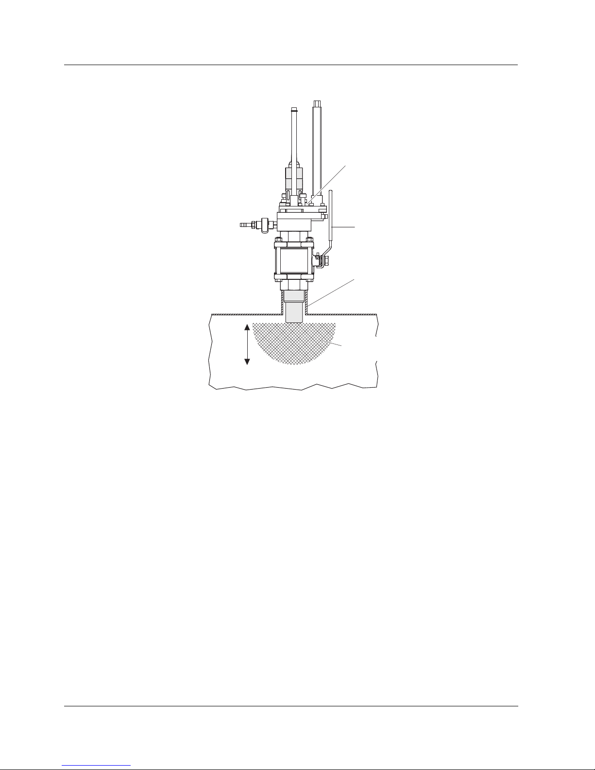
C + No risk of contamination by long fi-
bers
+ Low risk of damage from stones
and abrasive particles
- Susceptible to the capture of air
bubbles or large particles in front
of the sapphire disc (turbulence
effect)
In the case of contamination by
fibers, less prone to contamina-
tion than A.
B + Good flow of the sapphire disc, so
there is no interference from air
bubbles or large particles in front
of the sensor
- Risk of light reflections in narrow
containers
Good possibility in sufficiently
large containers or high values
of turbidity/total suspended sol-
ids.