YX EP-8201 User manual

VoIP Phone
Model EP-8201
User Manual
Release 1.2

Table of Content EP-8201 User Manual
i
Overview .................................................................................................................. 1
1.1 VoIP Phone Features .........................................................................................2
1.2 Front View ......................................................................................................3
1.3 Bottom View....................................................................................................3
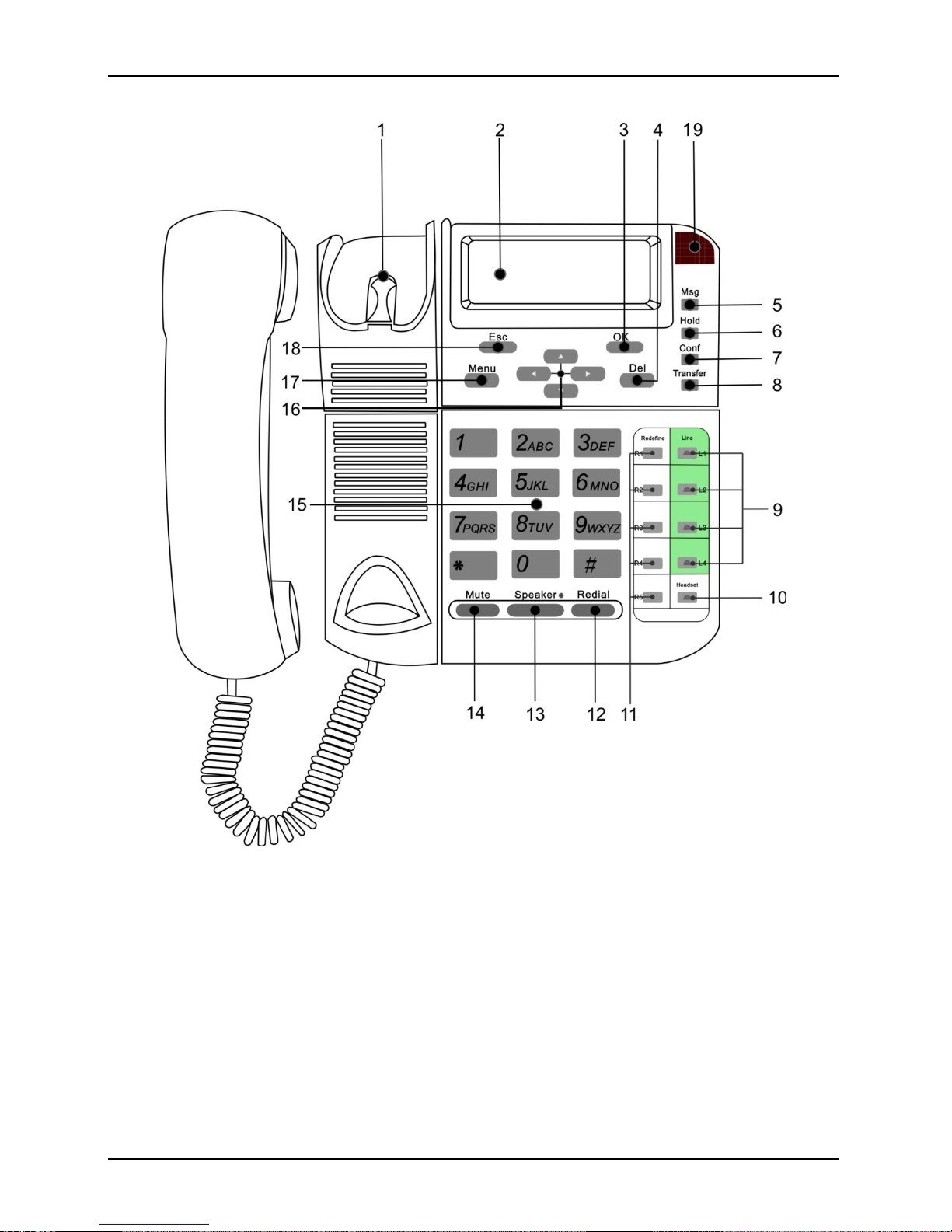
1.4 Structure ........................................................................................................4
Installation ................................................................................................................ 5
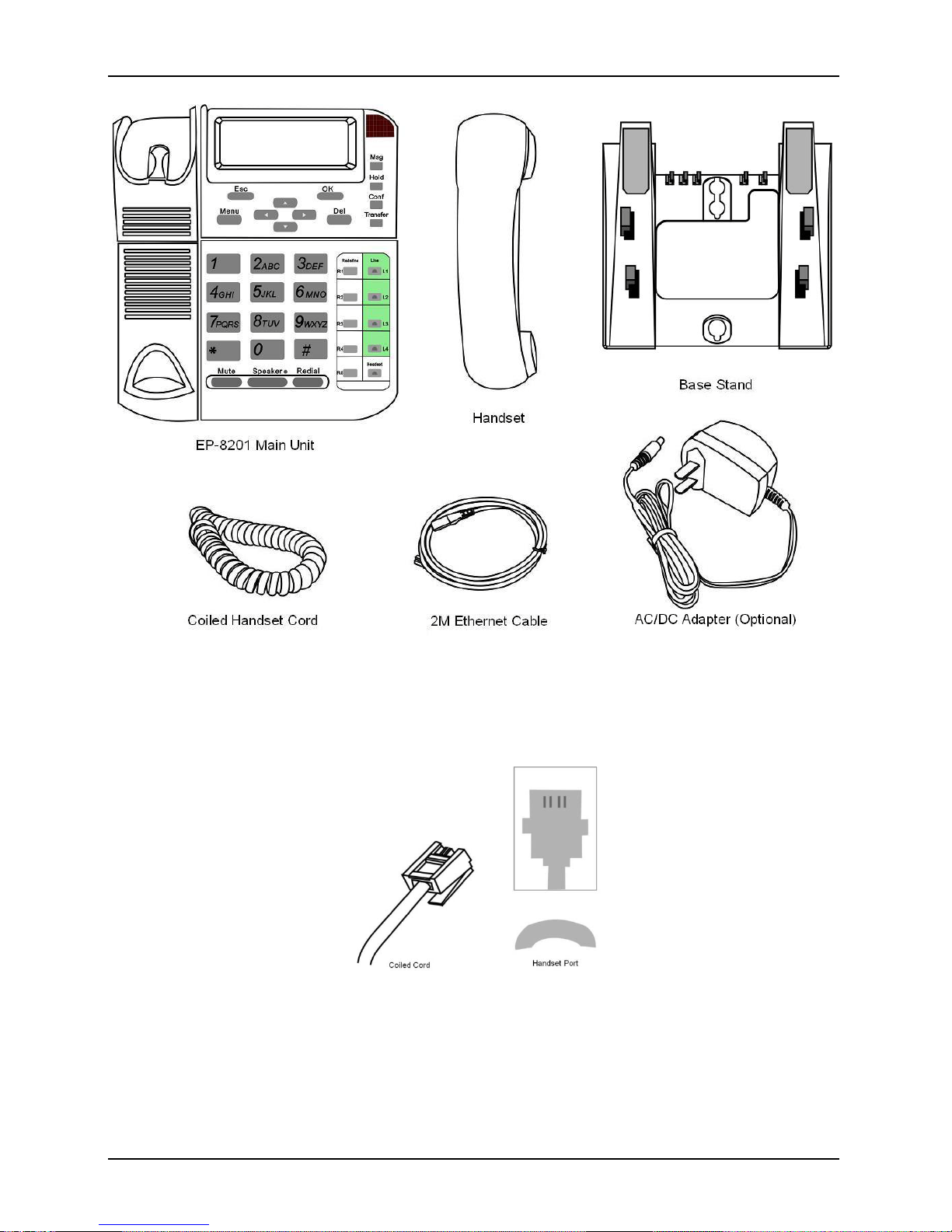
2.1 Package Contents.............................................................................................5
2.2 Setting Up EP-8201...........................................................................................6
2.3 Acquiring Network Port IP Addresses......................................................................7
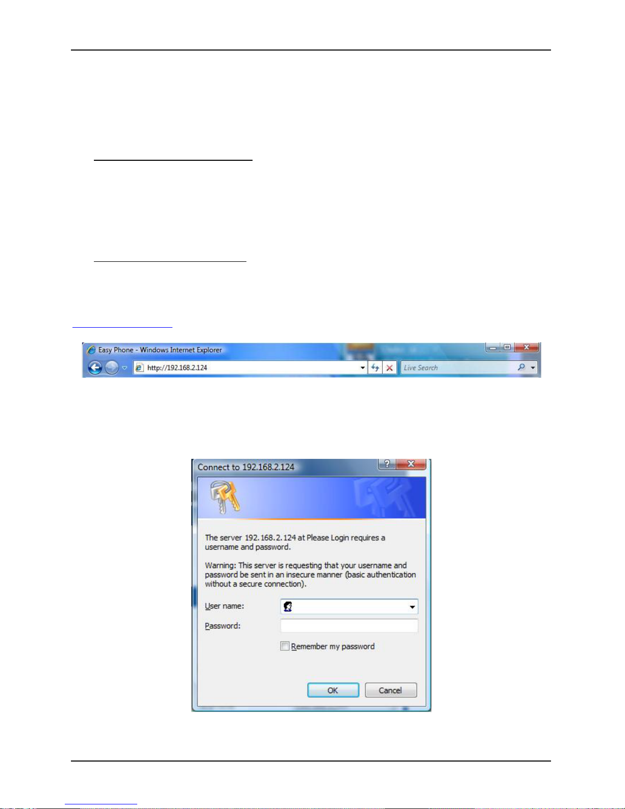
2.4 Accessing the Built-in Web Server..........................................................................8
Web Configuration.....................................................................................................11
4.1 Status Page .................................................................................................. 12
4.2 Configuration Page.......................................................................................... 12
3.2.1 Preference................................................................................................. 13
3.2.2 Network Configuration ................................................................................... 15
3.2.3 Call Settings............................................................................................... 17
3.2.4 Phone Settings............................................................................................ 26
3.2.5 Save Changes ............................................................................................ 28
3.2.6 Discard Changes ......................................................................................... 28
4.3 Phone Book .................................................................................................. 28
3.3.1 Edit a Phone Book Entry ................................................................................ 29
3.3.2 Delete a Phone Book Entry............................................................................. 30
3.3.3 Add a Phone Book Entry ................................................................................ 30
3.3.4 Backup / Restore Phone Book ......................................................................... 30
3.3.5 Auto Update ............................................................................................... 31
4.4 Tools........................................................................................................... 31
3.4.1 Tools........................................................................................................ 32
3.4.2 Change Password........................................................................................ 32
3.4.3 Backup / Restore Configurations....................................................................... 33
3.4.4 Reset Configuration...................................................................................... 33
3.4.5 Reboot...................................................................................................... 33
4.5 Gain Settings................................................................................................. 33
Phone Menu .............................................................................................................36
4.1 Call History ................................................................................................... 37
4.2 Phone Book .................................................................................................. 38
4.3 Message Center ............................................................................................. 38
4.4 System Tools................................................................................................. 39
4.5 Device Config ................................................................................................ 40
Phone Operation .......................................................................................................41
5.1 Making a Call................................................................................................. 41
5.2 Making a Hands-Free Call ................................................................................. 41
5.3 Answering an Incoming Call ............................................................................... 42
5.4Dialing from the Phonebook ............................................................................... 42
5.5 Viewing / Dialing from the Call History ................................................................... 42
5.6 Redialing the Last Number................................................................................. 42
5.7Speed Dial .................................................................................................... 43
5.8 Putting / Releasing a Call on Hold ........................................................................ 43
5.9 Transferring a Call........................................................................................... 43
5.10 Answering a Call Waiting Call ............................................................................. 44
5.11 Adjusting the Ringing Volume ............................................................................. 44
5.12 Adjusting the Handset Receiver Volume................................................................. 44
5.13 Adjusting the Speaker Volume ............................................................................ 44
5.14 Adjusting the LCD Contrast................................................................................ 45
5.15 Resetting Phone Configuration............................................................................ 45

Overview EP-8201 User Manual
1
1
Overview
The EP-8201 VoIP Phone is fully compatible with the open SIP industry standards. This
feature-rich VoIP Phone is designed as an enterprise grade VoIP device to work seamlessly
with most of the existing SIP systems.
Figure 1-1 EP-8201 VoIP Phone

Overview EP-8201 User Manual
2
1.1 VoIP Phone Features
The EP-8201 VoIP Phone has the following features:
Standard SIP
Standard Protocols: TCP/UDP/IP, RTP, HTTP, HTTPS, ARP, DNS, DHCP, NTP/SNTP, FTP,
TFTP, and SSL
VoIP Speech codecs: including G.711 a-law and u-law, GSM, G.723.1, G.729a/b/ab
Interoperable with various 3rd party VoIP end user devices, Proxy/Registrar/Server, and
gateway products
Up to 4 SIP registrations (same server or different servers) with BASIC or DIGEST
authentication (MD5, MD5-sess)
Full-duplex Speakerphone with echo cancellation
Handsfree operation via speakerphone or headset mode
Standard phone features: Caller ID Display, Call Waiting, Call Hold, Call Transfer, Call
Forward, Call Conference, Call History, Speed Dial, Phonebook
Special phone features: Dial Plan, Hotline, Voice Mail
DTMF modes: In-band and out-of-band DTMF (RFC2833/SIP INFO) dialing
Dial Plan
128 x 64 dot matrix LCD (sixe: 4 cm x 7 cm) with backlight and 4-level contrast controls
4 ring types, 6 ringing levels (including silence level)
6-level volume controls for both speakerphone and headset modes
DHCP Client, Static IP, PPPoE support for the LAN Port
Built-in network switch or router for the PC Port
Backup Server support for Single Server Mode
Jitter Buffer, VAD, CNG and PLC
Redundant DNS support
QoS Support (ToS / VLAN)
Built-in Web Server for Device Configuration
Built-in Phone Menu
Auto Firmware Upgrade and Phonebook Update
Auto Provisioning via http/ftp/tftp

Overview EP-8201 User Manual
3
1.2 Front View
Figure 1-2 EP-8201 Front View
1.3 Bottom View
Figure 1-3 EP-8201 Bottom View

Overview EP-8201 User Manual
4
1.4 Structure
Figure 1-4 EP-8201 Structure
1 Hook Switch 6 Hold key 11 Redefine keys
(R1/R2/R3/R4/R5) 16 Navigator keys (UP/
DOWN/LEFT/RIGHT)
2 LCD
7 Conf. key (Conference)
12 Redial
17 Menu key
3 OK key
8 Transfer key
13 Speaker key + LED
18 ESC key (Escape)
4 Del key (Delete) 9 Line keys + LED
(L1/L2/L3/L4) 14 Mute key 19 Visual Indicator
(Red LED)
5 Msg key (Message)
10 Headset key + LED
15 Dialing Keypad

Installation EP-8201 User Manual
5
2
Installation
Please follow the steps below to prepare and install the EP-8201.
1. Unpacking the EP-8201 gift box.
2. Checking the contents as described in Section 2.1.
3. Connecting the EP-8201 as described in Section 2.2.
4. Powering up the EP-8201.
5. Acquiring EP-8201 Phone IP address.
6. Configuring EP-8201 via Web Browser.
7. Configuring EP-8201 via Phone Menu (Basic settings only).
2.1 Package Contents
EP-8201 is shipped with the following items as shown in Figure 2-1 below:
1. One EP-8201 main Boad
2. One Handset
3. One Coild Handset cord
4. One Base Stand
5. One Ethernet Cable
6. One AC/DC Adapter - 12VDC/500mA Output (Optional)
Note: This is not required if your network switch supports POE.

Installation EP-8201 User Manual
6
Figure 2-1 EP-8201 Package Content
2.2 Setting Up EP-8201
1. Connect the coiled telephone cord to handset and the base of the VoIP Phone.
2. Use the enclosed (or equivalent) Ethernet cable to connect the LAN port to a hub or
switch, or to a DSL Router or Cable Modem.

Installation EP-8201 User Manual
7
3. If network does not support PoE, connect the power supply to the DC Jack on the
bottom of the EP-8201 (Use the one enclosed or equivalent).
4. For the first time installation, the phone will scan the network for available services
which are DHCP, PPPoE, and Fixed IP. Select the preferred service and enter the
required information if needed. No user input is required for DHCP service. User ID
and Password are required for PPPoE. IP address, Netmask, and Gateway IP
Address are required for Fixed IP mode.
2.3 Acquiring Network Port IP Addresses
Once the EP-8201 is properly setup and powered up, the IP Addresses assigned to the LAN
port and PC port can be retrieved via the Phone Menu as described below.
Press .
Press (System Tools).
Press (Phone Status).
Press (LAN Port) to view the LAN port IP.
The phone LCD displays:
LAN PORT
•STATUS: WORKING.
•IP: xxx.xxx.xxx.xxx
where xxx is any valid IP address between 0 and 255.
Or Press (PC Port) to view the PC port IP. If the PC port is set to Bridge
Mode, there is no IP address assigned. In this case, a PC connected to this port is in
the same network segment as the LAN port.

Installation EP-8201 User Manual
8
2.4 Accessing the Built-in Web Server
The built-in Web Server can be accessed by entering the LAN / PC IP address in a web
browser. Please see below to determine which IP Address to be used to access the built-in
Web Server.
Use LAN Port IP address when:
1. A PC and the LAN port are connected to the same network segment. This condition
applies to a PC connected to the PC port when it is set to Bridge Mode.
2. LAN IP address is public and the PC has internet access.
Note: If a private IP is assigned to the LAN port, it may still be accessed from the internet
provided that the local router is set up properly. Please consult your network administrator for
more information.
Use PC Port IP address when:
1. The PC Port is set to Fixed IP mode and a PC is connected to the same network
segment. Please make sure that the PC IP is setup properly.
To access the built-in Web Server, type the proper IP address (for example: 192.168.2.124 or
http://192.168.2.124 in the address field of a Web Browser (IE, Firefox, etc.).
Figure 2-2 Entering Phone IP Address to a Web Browser
Once the EP-8201 responds to the HTTP request, the Web Browser will prompt for a login
window as shown below.
Figure 2-3 Web Browser Authentication Window

Installation EP-8201 User Manual
9
EP-8201 supports two login levels.
For Administrator, please enter User name = “admin” and Password = “admin” (factory
default).
For User, please enter User name = “user” and the Password = “1234” (factory default).
Both passwords can be changed in the Administrator mode. Only user password can be
changed in the User mode. Please keep a record of the new passwords if changed. There is a
Star Command to reset the passwords to the factory defaults (Please see section x.xx for more
information).
The Administrator mode allows full access to the built-in Web Server whereas the User mode
restricts the user from accessing the Call Settings page.


Web Configuration EP-8201 User Manual
11
3
Web Configuration
Once the login is successful, the Web Browser brings up the Status page as shown below. The
built-in Web Server is divided into five categories: Status, Configurations, Phone Book,
Tools, and Logout. They can be access by clicking on the left hand menu column.
Figure 3-1 EP-8201 Built-
in Web Server – Status
Page

Web Configuration EP-8201 User Manual
12
4.1 Status Page
The Status page provides a brief summary on the Phone (Device) and Network information.
Phone Information
a) Profile X Number
Up to 4 Profiles can be defined; each profile contains one phone registration to the same
or different server.
b) Profile X Status
This field shows the status of server registration for each profile. If the device registers
to the designated server successfully, it displays “LOGIN”; otherwise, it displays
“LOGOUT”. If the profile is not defined, it display “NO CONFIG”.
c) Serial Number
Each EP-8201 is assigned with a unique serial number by the factory. This number is
important for auto provision, technical support, and warranty service. This serial number
is also printed on the product label at the bottom.
d) Firmware Version
This field identifies the current Firmware Version installed.
e) Hardware Model
This field identifies the hardware model and version.
Network Information
a) LAN Port
This field shows IP address assigned to the LAN port.
b) PC Port
This field shows IP address assigned to the PC port.
c) PPPoE
This field shows the dial up status when PPPoE is enabled for ADSL login.
d) Default Route
The Default Route shows the IP address of the default gateway / router that is used in
the current network environment.
e) DNS Server
This field shows the IP address of the DNS server to be used for domain name
interpretation.
4.2 Configuration Page
To access the Configurations page, click on the “Configurations” tab on the left hand column.
This brings up all the pages under this tab: Preference, Network, Call Settings, and Phone
Settings.

Web Configuration EP-8201 User Manual
13
3.2.1 Preference
This page configures the general settings in the device: Language, Time Zone, Display SIP
Server Time, Time server, Time Format, Auto-Provision, Key(#), Phone Book Mode,
Network Tones, Speaker Phone Mic Input Gain, and Central Management.
Figure 1-1 Configurations Page – Preference
a) Language - This field sets the language to be used for initial access to the built-in Web
Server. The languages currently available for selection are English and 简体中文(Simplified
Chinese). Once the language change is saved, it does not take effect until the web server
restarts.
Figure 1-2 Webpage Language Selection
To change the display language immediately, you can select the language icon located at
the top right hand corner (as shown below). However, this does not change the default
language.
Figure 1-3 Viewing Language Selection
b) Time Zone – This parameter specifies your local time zone in order for the date/time to be
correctly displayed since the date/time obtained from a network time server is referenced to
the Greenwich Mean Time (GMT). If your time zone is 8 hours ahead of the GMT, you need
to enter the value “GMT+8” in this field.
c) Display SIP Server Time – This parameter enables the phone to receive the data/time
information from the designated SIP Server. If this is enabled, the Time Server parameter
below will be disabled automatically.

Web Configuration EP-8201 User Manual
14
d) Time Server – This parameter specifies the location of the network time server for obtaining
the date and time information. It accepts both domain name and IP address. If the Display
SIP Server Time is enabled, this parameter is disabled automatically.
e) Time Format – This specifies the display time format (12-hour or 24-hour).
f) Auto Provision – This parameter enables or disables the Auto Provision procedures. The
Auto Provision is a batch script to obtain configuration and firmware upgrade information
from a server. Once this option is enabled, two additional parameters (Provision Server
and Provision Interval) are displayed. The Provision Server specifies the location of the
designated provision server. The auto provision procedure is executed at boot up time and
is repeated at a duration specified in the parameter Provision Interval.
Figure 1-4 Auto Provision Setting
g) Key(#) – When dialing a VoIP number, the VoIP device needs to wait for the user to
c8omplete the number dialing before the call request is actually sent to the server. This
parameter enables or disables the “#” key to be used to signal the number dialing is
completed and the call request can be execute immediately.
h) Phone Book Mode – This parameter defines if one phone book is used for all four profiles
(Global) or for each profile (By Line).
i) Network Tones – This parameter defines the network tones to be used. The predefined
networks tones are: China, Hong Kong, Taiwan, New Zealand, United Kingdom, United
States, Korea, Slovenia, Czechoslovakia, India, Singapore, Israel, Malaysia, Indonesia,
Thailand, Romania, Bangladesh, and Customized. The Customized option allows user
to define his own network tones. If the desired network tones selection is not available, user
can use this Customized option.
Figure 1-5 Network Tones Setting
Each network tone is defined as
nc, rpt, c1on, c1off, c2on, c2off, c3on, c3off, f1, f2, f3, f4, p1, p2, p3, p4,
where nc is the number of cadences
rpt is the repeat counter(0 - infinite, 1~n - repeat 1~n times)
c1on is the cadence one on duration (in milliseconds)
c1off is cadence one off duration (in milliseconds)

Web Configuration EP-8201 User Manual
15
c2on is the cadence two on duration (in milliseconds)
c2off is the cadence two off duration (in milliseconds)
c3on is the cadence three on duration (in milliseconds)
c3off is the cadence three off duration (in milliseconds)
f1 is the tone #1, 300-3000(Hz)
f2 is the tone #2, 300-3000(Hz)
f3 is the tone #3, 300-3000(Hz)
f4 is the tone 34, 300-3000(Hz)
p1 is the attenuation index for tone #1, 0~31(0=3dB, -1dB increments)
p2 is the attenuation index for tone #2, 0~31(0=3dB, -1dB increments)
p3 is the attenuation index for tone #3, 0~31(0=3dB, -1dB increments)
p4 is the attenuation index for tone #4, 0~31(0=3dB, -1dB increments)
Two examples of network tone definition are shown below.
1. A New Zealand Dial Tone (400 Hz) is defined as 0,0,0,0,0,0,0,0,400,0,0,0,10,0,0,0.
2. A New Zealand Busy tone (400Hz with a cadence of 500ms on and 500ms off (repeat)) is
defined as 1,0,500,500,0,0,0,0,400,0,0,0,10,0,0,0.
j) Speakerphone Mic Input Gain – This parameter is intended to tune the Speakerphone
performance. Increase the Mic gain if the volume heard at the other party is low. Reduce
the Mic gain if the echoes or howling occurs locally.
k) Centralized Management – This is a proprietary protocol to support remote management of
the EP-8201. Please consult your local agent or representative for more information.
3.2.2 Network Configuration
This page configures the network interface for the LAN Port and the PC Port.
Figure 1-6 Network Configuration
LAN Port
The LAN port is intended for internet access. It is normally connected to a network device
(router or ADSL modem) for internet access. Three operational modes are supported.

Web Configuration EP-8201 User Manual
16
Figure 1-7 LAN Port Setting (Mode Selection)
•DHCP – This mode should be selected If the network device functions as a DHCP host, This
allows the HT-812P to obtain all related network information / settings from the DHCP host.
•Static IP – This mode sets the LAN port IP manually which can either be a public or private
IP. Other network settings (Subnet Mask, Default Route, Primary DNS, Secondary DNS)
should also be entered accordingly.
Figure 1-8 LAN Port Setting (Static IP)
•PPPoE – This selection is intended for broadband connection (ADSL / Cable modem) that
requires dial up / authentication using PPPoE protocol. Both User Name and Password
are required. Please consult your service provider for more information if needed. One
advantage with the PPPoE dial up is that the IP address obtained for the LAN port is
normally a public IP.

Web Configuration EP-8201 User Manual
17
Figure 1-9 LAN Port Setting (PPPoE)
More advanced parameters for 802.1q VLAN and MAC settings are available. Please consult
your network administrator for assistance if needed.
PC PORT
The PC port is intended to provide an Ethernet connection to other network devices (for
example: PC, network HUB.). Two modes of operation are available:
1. Bridge mode - This mode allows the network traffics at the PC port to be bypassed to LAN
port. This means that the network device share the same network segment as the LAN
port. There is no IP address assigned to the PC port.
2. Fixed IP - This mode sets the PC port IP Address (private IP) and Subnet Mask manually.
This creates a new network segment for the network devices connected to the PC Port.
Figure 1-10 PC Port (Fixed IP)
To simplify network IP assignments, enable the DHCP Server for the PC Port. This allows
network devices connected Port to obtain network IP and related information from the PC
Port. Please consult your network administrator for proper settings of the DHCP Server
Figure 1-11 PC Port DHCP Host Setting
3.2.3 Call Settings
The Call Settings page configures all related settings for VoIP Service. The EP-8201 is SIP
compliant and it supports up to 4-line appearances in two registration modes: Single Server
and Multiple Servers.

Web Configuration EP-8201 User Manual
18
1. Single Server Mode – This mode allows SIP registrations to only one SIP Server / Proxy;
however, it can support up to 4 registrations of different SIP numbers and names (referred
as “Contact” in the webpage). A backup server option is available and it will be used once
registration to the primary server fails. Line 1 to Line 4 keys are predefined for the
“Contact1”, “Contact2”, “Contact3”, and “Contact4” respectively. This allows the user to
specify which identity (Contact: SIP number and name) will be used for the call. The default
is to use the contact information for Line1 (“Contact1”). Below shows the webpage for
Single Server Mode.
Figure 1-12 Single SIP Server Mode
2. Multiple Server Mode – This mode allows up to 4 SIP registrations to up to 4 different SIP
servers / proxies as shown below. Each registration is referred as a “Profile”. Line 1 to
Line 4 keys are predefined for Profile 1 to 4 respectively. If a “Profile” is not defined, the
corresponding Line key is disabled. If a call is made without pressing a Line key, the
default line to be used is Line 1 (Profile 1). Below shows the webpage for Multiple
Server Mode.
Table of contents