Z-Wave.Me ZME_05459 User manual

20-2-2014 manuals.zwaveeurope.com/make.php?lang=en&type=&sku=ZME_05459
http://manuals.zwaveeurope.com/make.php?lang=en&type=&sku=ZME_05459 1/7
ZME_05459
Wall Blind Control Set for Busch-Jaeger DURO 2000
Firmware Version : 1.8
Quick Start
A This device is a Z-Wave Actuator. Triple click one of the buttons on the device will include the device. A green blinking of LED will indicate
successful inclusion. The device is excluded by triple click to one of the buttons.
Please refer to the chapters below for detailed information about all aspects of the products usage.
What is Z-Wave?
This device is equipped with wireless communication complying to the Z-Wave standard. Z-Wave is the international standard for w ire le ss
c om m u nic ation in smart homes and buildings. It is using the fre que ncy of 868. 42 MHz to realize a very stable and secure communication. Each
message is reconfirmed (tw o- w ay com m unication) and every mains powered node can act as a repeater for other nodes (m e shed ne tw ork) in case
the receiver is not in direct wireless range of the transmitter.
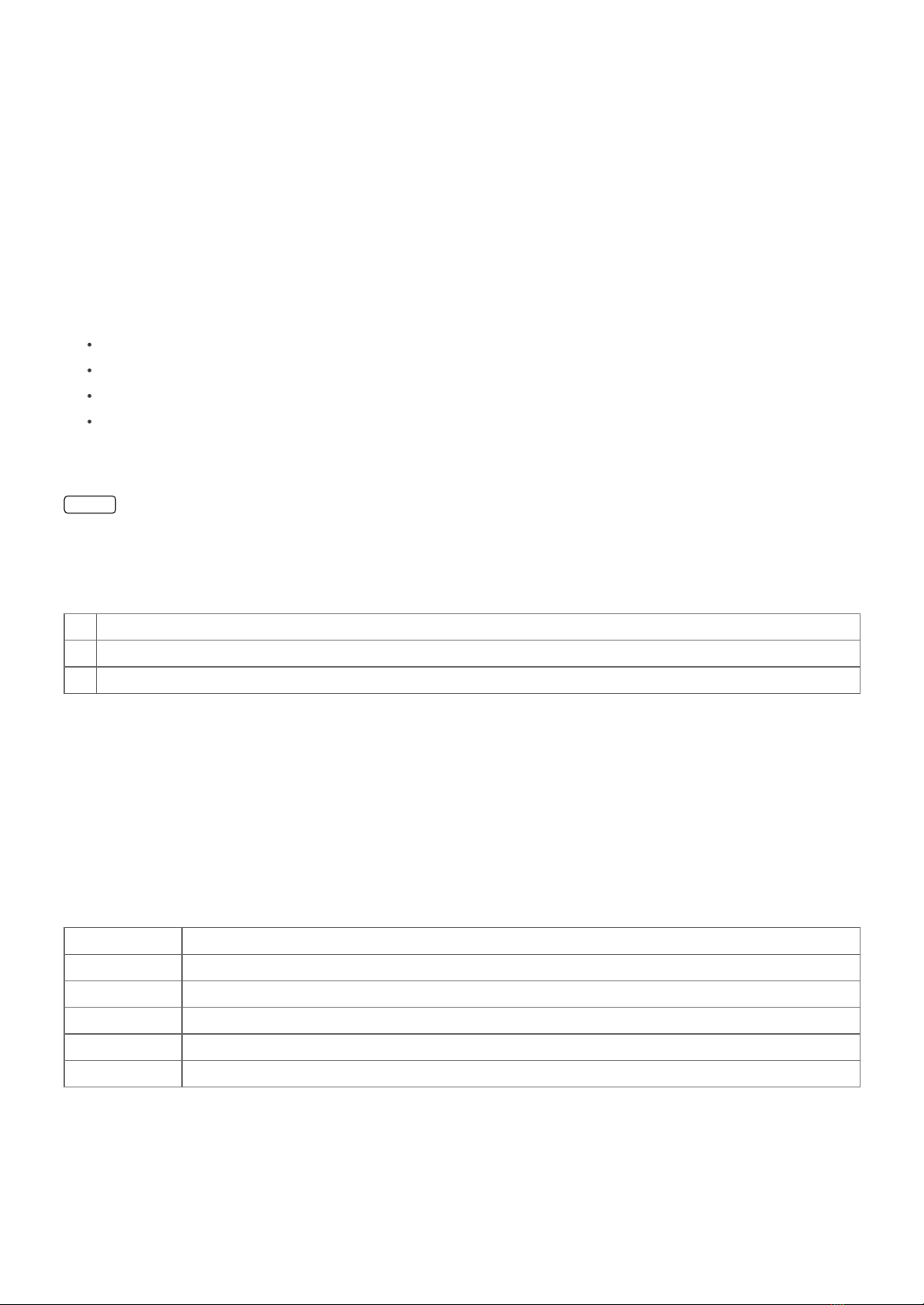
Z-Wave differentiates between Controllers and Slaves. Slaves are either sensors (S) transmitting metered or measured data or actuators (A) capable to
execute an action. Controllers are either static mains powered controllers (C) also referred to as gateways or mobile battery operated remote controls (R).
This results in a number of possible communication patterns within a Z-Wave network that are partly or completely supported by a specific device.
1. Controllers control actuators
2. Actuators report change of status back to controller
3. Sensors report change of status of measured values to controller
4. Sensors directly control actuators
5. Actuators control other actuators
6. Remote controls send signals to static controllers to trigger scenes or other actions
7. Remote controls control other actuators.
There are two different role a controller can have. There is always one single primary controller that is managing the
network and including/excluding devices. The controller may have other functions - like control buttons - as well. All
other controllers don't manage the network itself but can control other devices. They are called secondary controllers.
The image also shows that its not possible to operate a sensor just from a remote control. Sensors only communicate with static controllers.
Product description
The Z-Wave.Me Flush Mountable Motor Control is a wireless actuator able to control 230 V powered motors for blinds and jalousies. The device is
delivered as a complete set with flush mountable insert, paddle and mounting frame compatible to the design of the switching series DURO 2000 SI in
color pearl white from Busch Jaeger. The paddle of the device is used to control the device itself but can also be configured to activate scenes in a central
IP gateway or controller. The status of the motor control is indicated on a dual color LED for test purposes and every status change is - if configured -
reported to a central IP gateway or controller. The function of the local paddle can be configured as detached from the local operation. In this local control
different devices are controlled by Z-Wave while the local actuator is controlled by other devices using Z-Wave. This device is designed for a 3 wire system
and needs a neutral wire in the wall box.
Before Device is installed
Please read carefully the enclosed user manual before installation of the radio-actuator, in order to ensure an error-free functioning.
ATTENTION: only authorized technicians under consideration of the country-specific installation guidelines/norms may do works with 230 Volt mains
power. Prior to the assembly of the product, the voltage network has to be switched off and ensured against re-switching.
The product is permitted only for proper use as specified in the user manual. Any kind of guarantee claim has to be forfeited if changes, modifications or
painting are undertaken. The product must be checked for damages immediately after unpacking. In the case of damages, the product must not be
operated in any case. If a danger-free operation of the equipment cannot be assured, the voltage supply has to be interrupted immediately and the
equipment has to be protected from unintended operation.
Installation Guidelines

20-2-2014 manuals.zwaveeurope.com/make.php?lang=en&type=&sku=ZME_05459
http://manuals.zwaveeurope.com/make.php?lang=en&type=&sku=ZME_05459 2/7
The insert is designed to fit into standard circular European wall boxes with 60 mm diameter. The insert combined with the mounting plate can be
screwed in top of the wall box using the two screws delivered with the device. The mounting frame is then attached to the mounting plate and the switch
is completed by pushing the switching paddle into the mounting frame. Mind the arrow on the inserts top side showing the mounting direction of the
insert. It is also possible to mount the insert without any local operation behind a cover or inside a lamp. The mounting plate, frame and the switching
paddle become useless in such a scenario.
The schematics below shows how to wire the actuator. The hot wired from the mains distribution panel is connected to the inserts contacts L. The contact
S is the switched contact and need to be connected to the cable to the load. The cable from the load is connected to neutral N. If there are both neutral
and hot wire in the wall box the neutral from the mains panel and the neutral to the lamp need to be connected. It is not harmful if the two connections L
and S are mismatched on the actuator.
A fuse protects the electronics of the actuator. The fuse is accessible on the top side of the device. Inside the plug there is the working fuse plus a spare
fuse.
CALIB RATIO N:
The device is able to position a blind on a desired percentage position (50 percent open) when controlled wirelessly. To allow this kind of positioning the
total travel times of the motor in opening and closing direction must be determined using a simple clock. The two values need to be configured as
configuration parameter 4 and 5. Be aware that the percentage settings will never be very accurate because the blind control actuator lacks a sensor to
determine the correct position.
Behavior within the Z-Wave network
I On factory default the device does not belong to any Z-Wave network. The device needs to join an existing wireless network to communicate
with the devices of this network. This process is called Inclusion. Devices can also leave a network. This process is called Ex clusion. Both processes are
initiated by the primary controller of the Z-Wave network. This controller will be turned into exclusion respective inclusion mode. Please refer to your
primary controllers manual on how to turn your controller into inclusion or exclusion mode. Only if the primary controller is in inclusion or exclusion
mode, this device can join or leave the network. Leaving the network - i.e. being excluded - sets the device back to factory default.
If the device already belongs to a network, follow the exclusion process before including it in your network. Otherwise inclusion of this device will fail. If
the controller being included was a primary controller, it has to be reset first.
Blinking red/green LED indicates that the device is in factory reset state. Once the controller is turned into inclusion mode triple click one of the
buttons on the de vice w ill inc lude the de vice. A green blinking of LED will indicate successful inclusion that will be turned off shortly afterwards.
The de vic e is excl ude d by triple clic k to o ne of the buttons when the controller is in exclusion mode.
Operating the device
The actuator is operated by the local switching paddles or wirelessly using Z-Wave commands (communication patterns 1, 4, 5 and 7). If the insert is
mounted correctly pushing the upper part of the paddle will turn the blind into the open position; pushing the lower part of the paddle will turn the blind
into the close position. Hitting the paddle during operation (moving motor) will stop the operation for safety reasons. Keeping the paddle pushed moved

20-2-2014 manuals.zwaveeurope.com/make.php?lang=en&type=&sku=ZME_05459
http://manuals.zwaveeurope.com/make.php?lang=en&type=&sku=ZME_05459 3/7
the motor until the desired position is reached. Releasing the paddle will stop the motor.
The device is also able to report status changes to a controller (communication pattern 2) and to remotely operate other devices (communication pattern
5) by sending wireless Z-Wave commands. In case the remote device is a switch as well the remote operation is similar to the local operation by pushing
upper to lower part of the switching paddle. However the device can also be configured with configuration parameter 13 and 14 to operate remote
dimmers. To dim a remote device the paddle needs to be pushed and hold (upper part to dim up, lower part to dim down). Its furthermore possible to
assign remote operation functions to the double click of the paddles.
Child Protection
The device can be turn into a child protection mode. In this mode all local operation is disabled.
The child protection mode MUST be turned on wirelessly. However in protected by sequence mode it is possible to unlock the device for local operation
with a triple click. The unlock state will last for 5 seconds.
LED Control
Red and green blinking continuously: Device is not included in a Z-Wave network
Red lights up for 3 seconds: Device was not included/excluded after being put into learn mode by triple press of up/down button
Green lights up for 3 seconds: The inclusion/exclusion was successful or new association was saved successfully
Green or no light: depending on settings of configuration parameter for LED control
Associations
A Z-Wave devices control other Z-Wave devices. The relationship between one device controlling another device is called association. In order to
control a different device, the controlling device needs to maintain a list of devices that will receive controlling commands. These lists are called
assoc iation groups and they are always related to certain events (e.g. button pressed, sensor triggers, ...). In case the event happens all devices stored in
the respective association group will receive a common wireless command.
Association Groups:
1 Single press and hold of up/down buttons (max. nodes in group: 14)
2 Double press and press-hold of up/down buttons (max. nodes in group: 14)
3 Send Reports on blind state change (max. nodes in group: 14)
Configuration Parameters
Z-Wave products are supposed to work out of the box after inclusion, however certain configuration can adapt the function better to user needs or unlock
further enhanced features.
IMPORTANT: Controllers may only allow to configure signed values. In order to set values in the range 128 … 255 the value sent in the application shall
be the desired value minus 256. For example: to set a parameter to 200 it may be needed to set a value of 200 minus 256 = minus 56. In case of two byte
value the same logic applies: Values greater than 32768 may needed to be given as negative values too.
LE D m ode ( Param eter Num ber 1, Param eter Size 1)
Set LED indication mode
Val ue D e scrip tio n
0 Disabled
1 Show working state
2 Show idle state
4 Show if not closed
3 Operated by Indicator Command Class (Default)
Autom atical ly ope n or c lose afte r ( Param eter Num ber 2, Param e te r Siz e 2)
If not zero, automatically open or close blind after a user defined time

20-2-2014 manuals.zwaveeurope.com/make.php?lang=en&type=&sku=ZME_05459
http://manuals.zwaveeurope.com/make.php?lang=en&type=&sku=ZME_05459 4/7
Val ue D e scrip tio n
0 Disabled (Default)
1 — 65535 sec
What to do on RF c lose comm and ( Param e te r Num ber 3, Param eter Size 1)
Defines how to interpret RF Off command. Can be used in conjunction with Auto Close function: Ignore - to open the door by motion detectors and close it
back after some amount of time: in case of multiple motion detectors each would try to open that would break logics; Open - to open on both On and Off
paddle press on the remote and close after some amount of time. Button close click will still work (if button operations are not disabled). Note that Dim
Down command will still begin close motion.
Val ue D e scrip tio n
0 Close (Default)
1 Ignore
2 Open
3 Open if closed else close
Full close tim e (Param eter Number 4, Param eter Size 1)
Time to go from opened to closed state. Used to estimate the current level. Note that in Permanent motion mode the reported value would a be Closed or
Opened, while all Basic and Multilevel Set values (1-99, 255) would Open except 0 value that would Close.
Val ue D e scrip tio n
0 Keep in permanent motion
1 — 255 seconds (Default 60)
Full open tim e ( Param eter Number 5, Param eter Size 1)
Time to go from closed to open state. This value may differ from Full close time for some blinds due to gravity. Used to estimate the current level. Note
that in Permanent motion mode the reported value would a be Closed or Opened, while all Basic and Multilevel Set values (1-99, 255) would Open
except 0 value that would Close.
Val ue D e scrip tio n
0 Keep in permanent motion
1 — 255 seconds (Default 60)
No de Id of the bloc king device ( Param eter Number 6, Param eter Size 1)
Id of the device which commands would be interpreted not as Open/Close, but as block/unblock. Usefull with door opening detector: if the door is open,
block the blind not to break shades while they move.
Val ue D e scrip tio n
0 Disabled (Default)
1 — 232 Node Id
On w hich c om m and from blo cking node to e nabl e the prote ctio n ( Param e te r Numbe r 7, Param ete r Size 1)
Defines which command from blocking device to interpret as closed door and hence, unprotected.
Val ue D e scrip tio n
0 on On (Default)
1 on Off
Stop o r Re vert if opposite button is pressed ( Param e te r Num ber 8, Param e te r Size 1)
Defines behaviour on open press while closing and vice versa. To allow Stop behavior when switched by remote, use Stop by Basic

20-2-2014 manuals.zwaveeurope.com/make.php?lang=en&type=&sku=ZME_05459
http://manuals.zwaveeurope.com/make.php?lang=en&type=&sku=ZME_05459 5/7
Val ue D e scrip tio n
0 Stop (by buttons and Binary) (Default)
2 Stop (by buttons, Binary and Basic)
1 Revert
Inve rt ope n and close re lays (Param eter Number 9, Param eter Size 1)
Allow exchanging open and close relays if blind control is wired to the motor incorrectly
Val ue D e scrip tio n
0 No (Default)
1 Yes
Typic al click tim e out ( Param e te r Num ber 10, Param e te r Siz e 1)
Typical time used to differentiate click, hold, double and triple clicks
Val ue D e scrip tio n
1 — 100 in 10ms units (Default 50)
Inve rt buttons ( Param ete r Number 11, Param eter Size 1)
Val ue D e scrip tio n
0 No (Default)
1 Yes
Sw itch by buttons ( Param e ter Num be r 12, Param eter Siz e 1)
If disabled, the local operations by buttons will not switch the load, but only send commands to On/Off association group. In this mode buttons are not
linked with the switch anymore. They can be used separately: buttons to control remote device, switch will operate by RF commands only.
Val ue D e scrip tio n
0 No
1 By single press and hold (Default)
2 By double press and press-hold
Action on button singl e press or hol d (Param e te r Num be r 13, Param e te r Siz e 1)
Defines which command should be sent on button single press or hold. Basic and Scene Activation commands are sent to Association group. Use Scene
Controller Conf to set up Scene ID for Scene Activation. Switch All commands are sent broadcast.
Val ue D e scrip tio n
0 Disabled
4 Switch On/Off and Dim (send Basic Set and Switch Multilevel) (Default)
1 Switch On/Off only (send Basic Set)
2 Switch All
3 Send Scenes
5 Send Preconfigured Scenes
Action on button doubl e pre ss or hol d (Param eter Num be r 14, Param eter Size 1)
Defines which command should be sent on button double press or press-hold. Basic and Scene Activation commands are sent to Association group. Use
Scene Controller Conf to set up Scene ID for Scene Activation. Switch All commands are sent broadcast. If not disabled, the device will wait for a click
timeout to see if the second click would be pressed. This will introduce a small delay for single click commands

20-2-2014 manuals.zwaveeurope.com/make.php?lang=en&type=&sku=ZME_05459
http://manuals.zwaveeurope.com/make.php?lang=en&type=&sku=ZME_05459 6/7
Val ue D e scrip tio n
0 Disabled (Default)
4 Switch On/Off and Dim (send Basic Set and Switch Multilevel)
1 Switch On/Off only (send Basic Set)
2 Switch All
3 Send Scenes
5 Send Preconfigured Scenes
Se nd the fo llow ing S witch All com m ands (Param eter Num be r 15, Param e ter Size 1)
Val ue D e scrip tio n
1 Switch off only (Default)
2 Switch on only
255 Switch all on and off
What to do on butto n D ow n press (Param ete r Number 16, Param eter Size 1)
Defines how to interpret button Down press. Depends on "Switch by buttons" parameter. If not Disabled this parameter will affect the action selected by
the latter parameter. Can be used in conjunction with Auto Off function.
Val ue D e scrip tio n
0 Close (Default)
1 Open if closed else close
2 Open
Action on Auto ope n or close fu nc tion (Param eter Num be r 17, Param eter Size 1)
Val ue D e scrip tio n
0 Close blinds (Default)
1 Open blinds
Command Classes
Supported Command Classes
Basic (version 1)
Binary Switch (version 1)
Multilevel Switch (version 3)
Version (version 1)
Indicator (version 1)
All Switch (version 1)
Multi Channel Association (version 2)
Configuration (version 1)
Manufacturer Specific (version 1)
Protection (version 1)
Node Naming and Location (version 1)
Association (version 2)
Multi Channel (version 2)
Scene Activation (version 1)
Scene Actuator Configuration (version 1)
Scene Controller Configuration (version 1)

20-2-2014 manuals.zwaveeurope.com/make.php?lang=en&type=&sku=ZME_05459
http://manuals.zwaveeurope.com/make.php?lang=en&type=&sku=ZME_05459 7/7
Controlled Command Classes
Basic (version 1)
Multilevel Switch (version 3)
All Switch (version 1)
Multi Channel (version 2)
Scene Activation (version 1)
Technical Data
Power Supply 230V ~50-60 Hz
Attachable Loads Motors up to 1800 W
Fuse Type: T 1.25 A H (Load 1.25 Ampere, high shutdown capacity), D: 5 mm, L: 20 mm
IP Rating IP 20
Frequency 868.42 MHz (SRD Band)
Wireless Range up to 100 m outside, on average up to 20 m inside buildings
Explorer Frame Support Yes
SDK 4.54 pl1
Device Type Slave with routing capabilities
Generic Device Class Multilevel Switch
Specific Device Class Motor Control Class C
Routing Yes
FLiRS No
Firmware Version 1.8
Explanation of Z-Wave specific terms
Controll er — is a Z-Wave device with capabilities to manage the network. Controllers are typically Gateways, Remote Controls or battery
operated wall controllers.
Slave — is a Z-Wave device without capabilities to manage the network. Slaves can be sensors, actuators and even remote controls.
Prim ary Controll er — is the central organizer of the network. It must be a controller. There can be only one primary controller in a Z-Wave
network.
Inclusion — is the process of bringing new Z-Wave devices into a network.
Ex clusion — is the process of removing Z-Wave devices from the network.
Association — is a control relationship between a controlling device and a controlled device.
Wake up Notific ation — is a special wireless message issued by a Z-Wave device to annonces that is is able to communicate.
No de Inform ation F ram e — is a special wireless message issued by a Z_Wave device to announce its capabilities and functions.
Disposal Guidelines
The product does not contain hazardous chemicals.
Do not dispose of electrical appliances as unsorted municipal waste, use separate collection facilities. Contact your local government for information
regarding the collection systems available. If electrical appliances are disposed of in landfills or dumps, hazardous substances can leak into the
groundwater and get into the food chain, damaging your health and well-being.
(c) 2012 Z-Wave Europe GmbH, Goldbachstr. 13, 09337 Hohenstein-Ernstthal, Germany, All rights reserved, www.zwaveeurope.com
Table of contents
Other Z-Wave.Me Controllers manuals
Popular Controllers manuals by other brands

Gossen MetraWatt
Gossen MetraWatt R2080 operating instructions

mensor
mensor CPC6050 operating instructions

TECH
TECH ST-408 user manual

Central Boiler
Central Boiler Fire Star II Operation manual

Emerson
Emerson FISHER LR128 Series installation guide

Tech Controllers
Tech Controllers EU-R-10S PLUS user manual

Full Gauge Controls
Full Gauge Controls MT-518Ri user guide

HANYOUNG NUX
HANYOUNG NUX TPR-3N instruction manual

CKD
CKD KBX-30E-U Series instruction manual

Sharp Energy
Sharp Energy Sun Flux User manual & installation guide

GTC Sound Innovations
GTC Sound Innovations REVPAD quick start guide

Riken Keiki
Riken Keiki RM-590 Series quick start guide