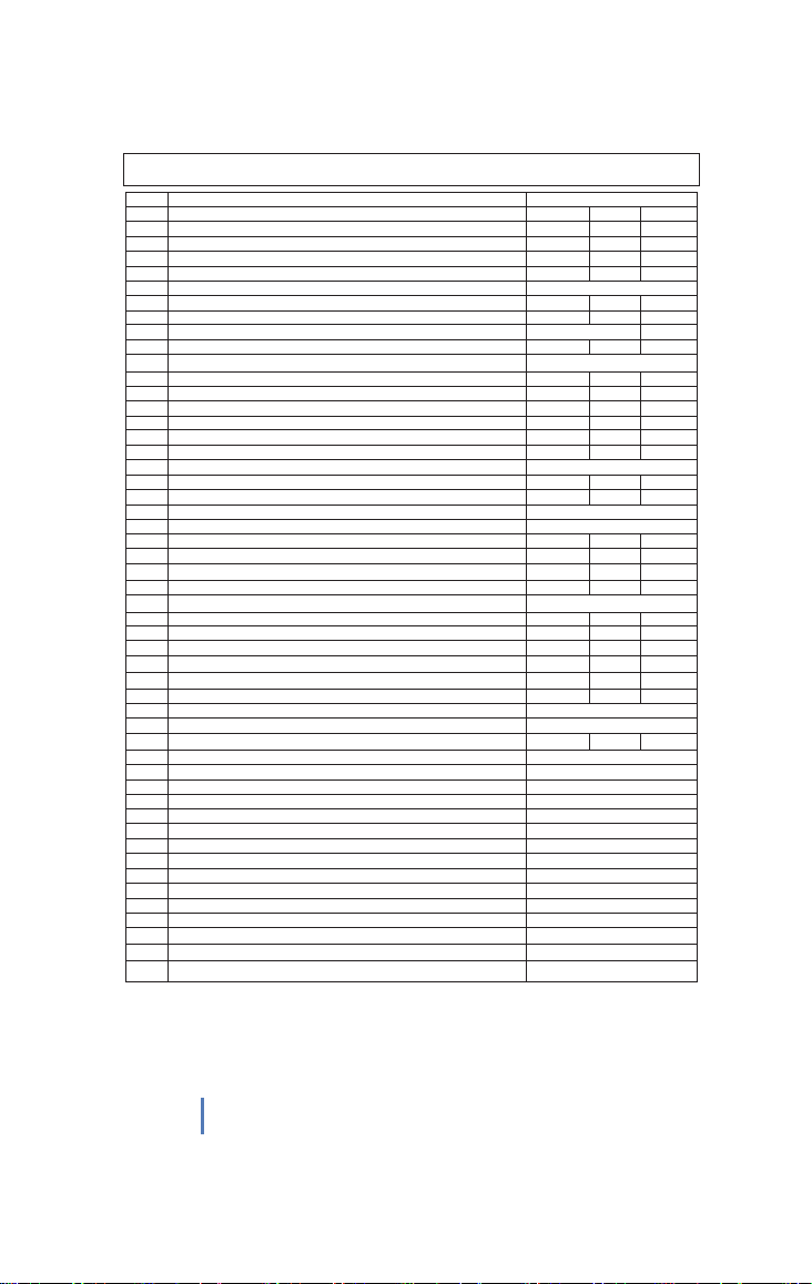
Zamp Solar SCC1011 User manual

1
Solar Controller / Battery Charger
SCC1011
Input: DC12V / 24V Solar panel (Max. 50V)
Output: DC 12V / 24V 40A
User’s Manual

2
●Advanced MCU control pulse width modulated (PWM) technology, high efficiency
operation.
●for LiFePO4, LTO (Lithium Titanium Oxide), LI-95, Gel, AGM, Conventional
lead-acid (WET) Batteries.
●Integrated regulator to prevent your battery from being overcharged. Overcharging
occurs when the charge voltage is unregulated. This can result in premature battery
failure.
●Integrated regulator to prevent your battery from being under charged, The unit
provides an automatic Equalization feature for deeply drained Conventional lead
acid battery, as well as provides a cycling automatic Equalizing feature every 28
days.
●Can be connected to the battery permanently to keep the battery fully charged by
using a process called “floating”. This means the controller will stop charging when
the battery is full and will automatically start charging the battery as required. This
process will also reduce water loss and help prevent the battery from ‘drying out’.
●Protects your battery from discharge at night. Under low light or no light conditions
the solar panel voltage could be less than the battery voltage. The unit contains a
special circuit which prevents current flowing back from the battery and into the
solar panel.
●Colored LED’sto easily indicate the operational status and battery conditions.
●Digital LCD to directly display battery voltage, charging current, charging capacity
(Amp hour), battery types and faulty codes.
●Provides plug-in remote digital display meter (Optional).
●Provides external battery temperature sensor (Optional).
●Multi charging protections against reverse polarity, short circuit, over temperature,
over voltage, etc.
●Surface Mount or Flush Panel Mount options.
●Conformal-coating circuit boards and plated terminals apply to hostile environments.
For use with 12/24Volt Solar Panel; Suitable for Solar panels up to
760 Watts on 12V mode; 1520Watt on 24V mode
FEATURE
SCC1011

3
●
This charger is designed for indoor use only and should never be exposed
to rain.
●Do not disassemble the controller. Take to a qualified person if the unit
requires repairing.
●Lead acid, LiFePO4, LTO, batteries can be dangerous. Ensure no sparks
or flames are present when working near batteries.
●Eye protection should always be used. Never short circuit the battery
●Given sufficient light solar panels always generate energy even when they
are disconnected.
●Accidental ‘shorting’ of the terminals or wiring can result in sparks causing
personal injury or a fire hazard. We recommend that you cover up the
panel(s) with some sort of soft cloth so you can block all incoming light
during the installation. This will ensure that no damage is caused to the
Solar Panel or Battery if the wires are accidentally short circuited.
●Always install a battery fuse on each circuit including the solar controller
●Do not reverse connect the wires to the solar panel or battery
WARNING – IMPORTANT PLEASE READ
MOUNTING THE DEVICE
The Solar Controller has two mounting options.
1. Surface mount:
The quickest and easiest way to mount the unit is to use the two plastic
spacers and self tapping screws supplied and mount the unit to a flat surface,
2. Flush (panel) mount:
Before deciding to use this mounting method, please ensure there is sufficient
depth behind the controller or in the cavity. (Refer to Diagram below)
Using the dimensions shown in the following diagram, mark a 105mm x
130mm rectangle where you wish to mount the controller and cut-out the panel
opening then use the two self - tapping screws supplied to secure the unit.

50A FUSE
50A FUSE
SCC1011
SOLAR BATTERY
4
To protect the Battery and the Solar Panel, we strongly recommend that you place a
50A inline fuse on the positive wire on both the “Solar” and “Battery” Circuits. (As close
to the Battery /Panel as possible)
The Solar Controller has 4 terminals which are clearly marked ‘Solar’ and ‘Battery’.
Battery Connection Solar Array Connection
Length of
Wire 5ft 10ft 10ft 15ft 20ft
Size (AWG) 10 8 10 8 8
1. Using the Terminals supplied, crimp the terminals on your Solar Array wires and
connect to the Solar Panel like shown.
2. Using the Terminals supplied, crimp the terminals on your Battery wires and
connect to the Battery like shown.
When the connections are completed, the Solar Controller will start working
automatically.
Please check your battery manufacturer’s specifications to select correct battery type.
The unit provides 6 battery mode for selections:LiFePO4, LTO, LI-95, Gel, AGM, WET
(conventional lead acid).
Correct Wire Size:
Please refer to the wire size chart
below to determine the minimum
size wire needed for each
connection. Thiswill also ensure
you get the best performance out
of your solar regulator.
WIRING CONNECTIONS
OPERATION - LCD DISPLAY
100%
AMP/
VOLT
BATTERY
TYPE
Hold for 3 sec. for setting

5
Press BATTERY TYPE button and hold for 3 seconds to go into your battery type
selection mode, the battery type you select will be shown on the LCD meter, the
default setting is AGM Battery; the controller will automatically memorize your battery
type setting.
Caution: Incorrect battery type setting may damage your battery.
When the controller powers on, the unit will run self -qualify mode and automatically
show below items on LCD before going into charging process
Self-test starts, digital meter segments test
Software version test
V
A
Rated voltage and current test
ºC
External battery temperature sensor test (if connected)
Indicates the solar panel connected.
After going into charging process, the LCD displays the charging statues as below:
Press VOLT / AMP button in sequence, the LCD will display in turn with
Battery Voltage, Charging Current, Charged capacity (Amp-hour) and Battery
Temperature (if external temperature sensor connected)
Display in the daytime-
V
A
V
ºC
Display during the night-
V
ºC
The VOLT / AMP button can be changed at any time during charging process.
You also can visually monitor your battery charging condition for each battery; there is
a LCD bar to show the percentage of charge, you can easily see the battery is charged
to 25%, 50%, 75% or 100%.
The LCD also can be treated as an independent voltage meter or thermometer.
A voltage less than 11.5V Volts indicates that the battery is discharged and needs
re-charging.
The unit has a 5-stage charging algorithm.
Soft Charge (Level 1) –Bulk Charge (Level 2)-Absorption charge (Level 3) –
Equalizing Charge* (Level 4)
-
Float Mode (Level
5
)
CHARGING STAGES

6
.
Soft Charge- When batteries suffer an over-discharge, the controller will softly ramp
the battery voltage up to 10V.
Bulk Charge-Maximum current charging until batteries rise to Absorption level
Absorption Charge-Constant voltage charging, and battery is over 85%.
Equalization Charge*-Only for WET battery type, when the battery is deeply drained
below 10V, it will automatically run this stage to bring the internal cells as
an equal state and fully complement the loss of capacity. (LiFePO4, LTO,
LI-95, Gel and AGM battery do not run Equalization charge)
Float Charge-Battery is fully charged and maintained at a safe level.
A fully charged Lead acid battery (GEL, AGM, WET battery) has a
voltage of more than 13.6 Volts; A fully charged LiFePO4 or LTO battery
has a voltage level of 13.4V.
Lithium batteries wake-up-If the BMS under-voltage protection has been triggered in
the lithium battery mode (LiFePO4, LTO or LI-95 ) , Pressing both VOLT/AMP
and BATTERY TYPEbutton, the solar controller will wake up the "dead" Lithium
batteries, The LCD display will showthe rotation of moving bar in this wake-up period.
The 6 LED’s indicate the
charging status and the
battery condition Red Blue Green Green Yellow Red
Solar Power Present-No
battery connected
ON OFF OFF OFF OFF Flash
Soft charging ON Flash OFF OFF OFF ON
Bulk charging ON ON OFF Subject to battery voltage
Absorption charging ON ON OFF ON OFF OFF
Equalization charging
ON ON OFF ON OFF OFF
Float charging ON OFF ON ON OFF OFF
Solar panel weak Flash OFF OFF Subject to battery voltage
At night, no charge OFF OFF OFF Subject to battery voltage
Battery Voltage below 11.5V
(+/-0.2V)
ON ON OFF OFF OFF ON
Battery Voltage between
11.5V - 12.5V(+/-0.2V)
ON ON OFF OFF ON OFF
Battery Voltage above 12.5V
(+/-0.2V)
ON ON OFF ON OFF OFF
.
OPERATION - L.E.D. INDICATION

7
Solar panel abnormal
modeLCD display LED indication LCD backlight
Solar panel weak Flash ON
Solar panel reverse
connection Flash Flash
Solar panel over voltage
(> 26.5V) Flash Flash
Battery abnormal mode LCD display LED indication LCD backlight
Battery disconnected o
r
less than 3.0V Flash Flash Flash Flash
Battery reverse
connection Flash Flash
Battery over voltage
than > 17.5V Flash Flash
Battery temperature over
65C Flash Flash Flash Flash
The solar controller
abnormal mode LCD display LED indication LCD backlight
The controller over
temperature protection Flash
.
The controller provides two optional devices ( excludes in the packaging box).
Optional external Battery temperature sensor:
As an option, the unit provides a port to connect the external battery temperature sensor;
if the external battery temperature sensor is connected, the unit will optimize the chargin g
performance subjected to the battery temperature detected and also provide the battery
over temperature protection, in some cases, if battery over temperature occurs, the
controller will automatically stop charging.
Optional external Remote display meter:
As an option, the unit also provides a port to connect the external Remote display meter
for some special location needed. The display content on the Remote meter is same as
the display on the controller.
OPTIONAL EXTERNAL DEVICE
.
ABNORMAL OPERATION MODE

8
1 Electrical Parameters
1-1 Rated solar panel short circuit current 40 Max. AMP
1-2 Normal input Solar cell array voltage 15-22 VDC
1-3 Max. solar cell array voltage (output has no load) 25 Max. VDC
1-4 The controller lowest operating voltage (solar or battery side) 8V Min VDC
1-5 Maximum voltage drop-Solar panel to battery 0.25 Max. VDC
2 Charging characteristics
2-1 Minimum battery start charging voltage 3 Min VDC
2-2 Soft start charging voltage 3-10 +/-0.2 VDC
2-3 Soft start charging current Up to 20 AMP
2-4 Bulk charge voltage 10-14.0 +/-0.2 VDC
2-5 Absorption charging voltage at 25℃
--LI-95 type battery (i ) 13.7 +/-0.2 VDC
--LTO type battery 14.0 +/-0.2 VDC
--Gel type battery 14.1 +/-0.2 VDC
--LiFePO4 battery 14.2 +/-0.2 VDC
--AGM type battery (default setting) 14.4 +/-0.2 VDC
--WET type battery 14.7 +/-0.2 VDC
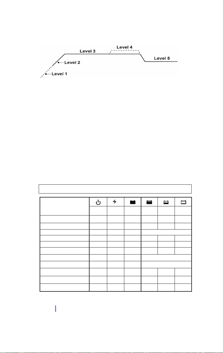
2-6 Absorption transits to Equalizing or Float condition:
--Charging current drops to 1.0 +/0.1 AMP
-- or Absorption charging timer timed out 4 Hour
2-7 Equalization charging active
--Only for WET battery
--Battery voltage discharged to less than 10 +/-0.2 VDC
--Automatic equalizing charging periodical 28 Day
2-8 Equalization charging voltage at 25 ℃15.5 +/-0.2 VDC
2-9 Equalization charging timer timed out 2 Hour
2-10 Float charging voltage at 25℃
-- For LI-95, LTO and LiFePO4 battery 13.4 +/-0.2 VDC
-- For Gel, AGM, WET, battery 13.6 +/-0.2 VDC
2-11 Voltage control accuracy +/- 1%
2-12 Battery temperature compensation coefficient -24 mV/℃
2-13 Temperature compensation range -20~+50 ℃
3 Protection
3-1 Against reverse polarity or short circuit
3-2 No reverse current from battery to solar at night
3-3 Over temperature protection during charging 65 ℃
3-4 Transient over voltage protection with TVS or varistor
4 Electrical parts
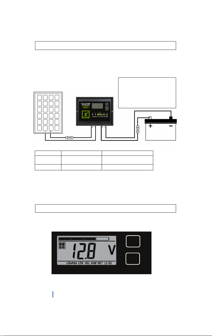
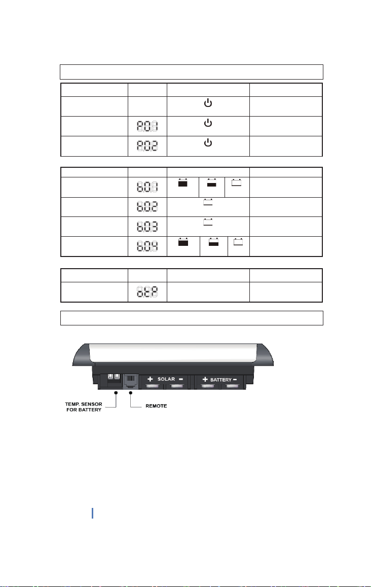
4-1 Input output terminal M5 terminals
4-2 Remote port RJ-11 (6 pins)
5 Physical Parameters
5-1 Controller material Plastic, Standard ABS
5-2 Power terminal maximum stranded wire size #6 AWG stranded-16 mm2
5-3 Power terminal torque Up to 17 in-lb (0.2n-m)
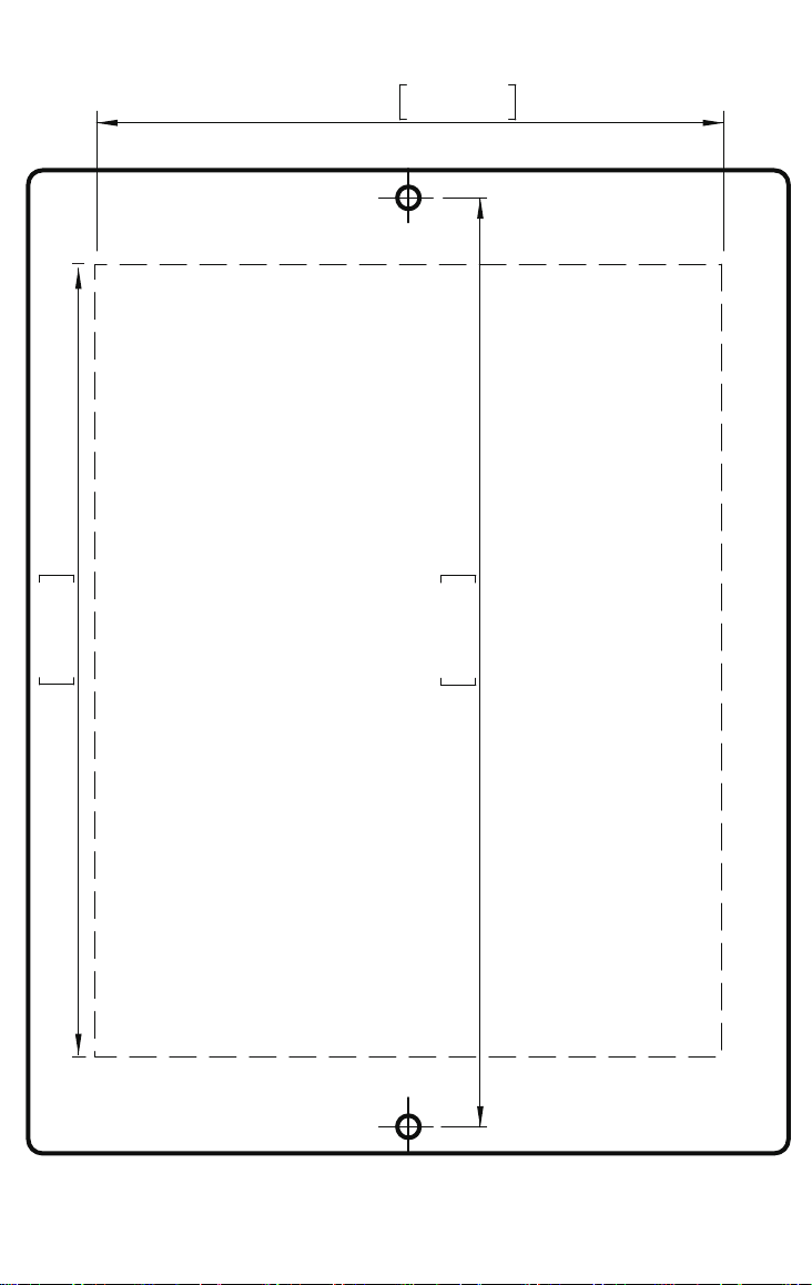
5-4 Mounting Vertical wall mounting
5-5 IP grade IP22,
5-6 Net weight Approx. 0.3kg / 0.66lb
6 Environmental characteristics
6-1 Operating temperature -25 ~ 50℃/ -13 ~ 122 ℉
6-2 Storage temperature -40 ~ 85℃/ -40 ~ 185 ℉
6-3 Operating Humidity range 100% no condensation
Remarks: Voltage settings for 12V mode, x2 for 24V mode.
( i ) The LI-95 battery profile keeps your LiFePO4 battery charged at 95%. Evidence suggests
that charging your Lithium battery to less than 100% can increase longevity of your battery.
SPECIFICATIONS

5.8in 148.2mm
5.0in 126.0mm
3.9in 100.0mm
Table of contents
Other Zamp Solar Batteries Charger manuals