Zamp Solar ZS-60A User manual

ZA,MF3
ScfLA,R
Solar Controller / Battery Charger
lnput: DGl2l24V Solar panel (Max. 50V)
Output: DC12|24V 60n
Model Number: 25-604
User's Manual

FEATURE
OThis solar controller is used for off-grid photovoltaic (PV) system, such as solar
home system, small power station, etc.
OThe charging management has been optimized to prolong battery life, and improved
system performance.
OThe solar controller provides a wide range of Battery type setting: Gel, AGM,
Conventional lead-acid (WET), Calcium, LiFePO4, LTO (Lithium Titanium Oxide)
Battery types selection.
Olndustrial grade MCU control, Pulse width modulated (PWM)technology, high
efficiency operation.
OBuilt in regulator to prevent the battery from being overcharged. Overcharging
occurs when the charge voltage is unregulated. This can result in premature battery
failure.
OCome with regulator to prevent the battery from being under charged, in the solar
energy field, battery undercharge always occurs, especially on some Conventional
lead -acid or Calcium batteries; The unit provides an automatic Equalization feature
for deeply drained Conventional lead acid battery or Calcium battery, as well as
provides a cycling automatic Equalizing feature every 28 days.
aProtects the battery from discharge at night. Under low light or no light conditions
the solar panel voltage could be less than the battery voltage. The unit contains a
special circuit which prevents current flowing back from the each battery and into
the solar panel.
OColored LED's to easily indicate the operational status and each battery conditions.
ODigital LCD to directly display the battery voltage, charging current, charging
capacity, battery type, ambient temperature and faulty codes.
OProvides plug-in remote digital display meter (Optional).
OProvides external battery temperature sensor (Optional).
OMulti charging protections against reverse polarity, short circuit, over temperature,
over voltage, etc.
OSurface Mount and weather proof.
OConformal-coated circuit boards and heavy duty terminals apply to hostile
environments.
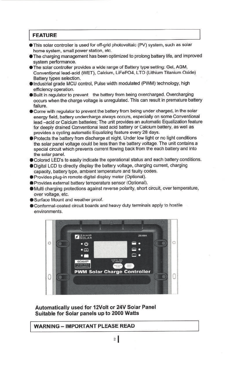
Automatically used for l2Volt or 24V Solar Panel
Suitable for Solar panels up to 2000 Watts
WARNING - IMPORTANT PLEASE READ
zl

O This solar controller is designed for indoor use only and should never be
exposed to rain or snow.
O Do not disassemble the controller. Take to a qualified person if the unit
requires repairing.
O Lead acid batteries, LiFePO4 or LTO batteries can be dangerous. Ensure
no sparks or flames are present when working near batteries.
O Eye protection should always be used- Never short circuit the battery
O Given sufficient light solar panels always generate energy even when they
are disconnected.
O Accidental 'shorting' of the terminals or wiring can result in sparks causing
personal injury or a fire hazard. We recommend that you cover up the
panel(s) with some sort of soft cloth so you can block all incoming light
during the installation. This will ensure that no damage is caused to the
Solar Panel or Battery if the wires are accidentally short circuited.
O Always install a battery fuse on each circuit including the solar controller
O Do not reverse connect the wires to the solar panel or battery
MOUNTING THE DEVICE
Choose a ¡ocat¡on
The 25-604 solar controller is designed to be mounted against a wall, out of
the way but easily visible, it should be:
o Mounted on a vertical surface to optimize cooling of the solar controller.
r Mounted as close to the battery as possible to reduce the voltage drop on
the cable.
o Mounted indoor, protected from the weather.
Note: lf the unit is installed in a RV, the most common controller location is
above the refrigerator. The wire from the solar array most commonly enters the
RV through the fridge vent on the roof.
Dimensions for installation: Please refer to the following fig 1 and fig. 2
182rrnl
Ê
C
E
o
0)
o
o
o
C)O
c'
0
:l Fig I

o
0
7\
o
o
o
o
o
C)O
-1l]
TË
N
s
)
172nm Fig.2:
INSTALLATION INSTRUCTIONS
Fig.3: The wiring diagram
PV Solar Charge Controller
o\J
12 I 24V Ballery
+l
Remote Display

2. ldentify the polarity (positive and negative) on the cable used for the battery and
solar panel, would be best to use colored wires or mark the wire ends with tags.
3. Keep the solar panel covered with an opaque material until all wiring is completed.
According to above the wiring schematic in fig.3, run wires from the solar panel
and the batteries to the location of the 25-604.
4. Take off the cover bar of the 23-60A, insert the cables into the power terminals as
identified locations (identified Solar or Battery connected terminals).
5. Tightly secured the terminal screws; ensure the cables are reliably installed into
the connection power terminals, and then pui back the cover bar to the controller.
Wiring Procedure:
1. Select the wire gauge as reference table as below:
Battery Connection Solar Array Connection
Length of
Wire <1m 6m 9m 12m
Size (AWG) 4or2 b42
Please refer to the following fig. 4
Fig. 4
6. After 30 days of operation, retorque all terminal screws to ensure the wires are
properly secured to the controller.
Caulion 1: The 80Amp inline fuses must be connected into the positive wires
as shown in the wiring schematic in fig.3
Caution 2: The 25-604 solar controller installation must be made by
specialized techn¡que person, any wrong size of wires used or
loose power connections or corroded wires can melt wire
insulation, burn surrounding materials or even cause a fire.
Ensure tight all connections and use cable clamps to secure
cables.
sl

NOTE: The 25-60A controller has a common negative, it does not matter which
Negative terminal is grounded.
when the connections are completed, the controller will start working automatically
OPERATION - LCD DISPLAY
Battery type settings:
Please check your battery manufacturer's specifications to select correct battery type.
The unit provides six (6) battery types setting for selections: Gel, AGM, WET
(conventional lead acid), Calcium, LiFePO4 and LTO battery.
Press BATTERY TYPE button and hold for 3 seconds to go into your battery type
selection mode, the battery type you seìect will be shown on the LCD meter, the
default setting is AGM Battery; the controller will automatically memorize your battery
type setting.
Gaution: lncorrect battery type setting may damage your battery'
when the controller powers on, the unit will run self-qualify mode and automatically
show below items on LCD before going into charging process
r:r r:r r:l
r:r.r:r.r:r Self-test starts, digital meter segments test
tt I
r- u. ¡ Software version test
t ]rt-t "
I r-.r-r Rated voltage test
l- l-rñ
l:lLl,U Rated current test
:rÈ "'
': :r External battery temperature sensor test (if connected)
ffi TJ.5 V
cALCrUl[
tiFePOl 110 GEL AGll
HXffi
Zffirilì
\.rvee _,¡\vou _¡
ol

l_
i3€l ¡¡¿¡ç¿1s the solar panel connected.
After going into the charging process, press VOLT / AMP button in sequence, the
LCD will display in turn with Battery Voltage, Charging Current, Charged capacity
(Amp-hour) and Battery Temperature (if external temperature sensor connected).
Display in the day time-
( l,:'.ii ' o!l!:i!-l ' o i,:'i:i^"+ ,1";, ')
Display during the night-(The current and Amphour are shown 0)
l,^lll,ll'l
\\ il:r:r d r- -r t)
The VOLT / AMP button can be changed at any time during charging process.
The LCD also can be treated as an independent voltage meter or thermometer.
A voltage less than 11.5V123.0 Volts indicate that the batiery is discharged and
needs re-charging.
You also can visually monitor your battery charging condition for each battery; there
is a LCD bar to show how many percentage capacities are charged, you can easily
see the battery is charged around 25o/o,50o/o,75o/o or 100V..
0ülå
CHARGING STAGES
The 25-60A has a 5 stage charging algorithm.
Soft Charge (Level 1) -Bulk Charge (Leveì 2)-Absorption charge (Level 3) -
Equalizing Charge* (Level 4) - Float Mode (Level 5)
Level 4
Level 3
Level 5
.-Level2
,'r-Level 1
tl

Soft Charge- When batteries suffer an over-discharge, the controller will softly ramps
the battery voltage uP to '10V / 20V.
Bulk Charge-Maximum current chargìng until batteries rise to Absorption level
Absorption Gharge-Constant voltage charging and battery is over 85%.
Equalization Charge*-Only for WET battery or Calcium battery iype, when the battery
is deeply drained below 10V I 20V , it will automatically run this stage to
bring the internal cells as an equal states and fully complement the loss of
capacity.(Gel, AGM,LiFePO4 and LTO baitery do not run Êqualization
charge)
Float Charge-Battery ¡s fully charged and mainiained at a safe level'
A fully charged battery has a voltage of more than 13.6 I 27.2Volts.
Auto Equalize: The 25-60A has an automatic equalize feature that will charge and
recondition your battery once a month at a high voltage to ensure that
any excess sulphation is removed and individual cells are balanced. This
feâture is available for Wet cell (flooded battery) or Calcium batteries.
Check with your battery manufacture,
OPERATION - L.E.D. INDICATION
The 6 LED's indicate the
charging status and the
battery condition
út +IIHÊf
Red Blue Green Green Yellow Red
Solar Power Present-No
battery connected ON OFF OFF OFF OFF Flash
Soft charging ON Flash OFF OFF OFF ON
Bulk charging ON ON OFF Subject to battery voltage
Absorption charging ON ON OFF ON OFF OFF
Equalization charging ON ON OFF ON OFF OFF
Float charging ON OFF ON OFF OFF OFF
Solar panel weak Flash OFF OFF Subject to battery voltage
At night no charge OFF OFF OFF Subject to battery voltage
Battery Voltage below 1 1.5v
(+/-0.2v) ON ON OFF OFF OFF ON
Battery Voltage betwèen
I I _5V -,t2.5Vt+/-0.2v) ON ON OFF OFF ON OFF
Battery Voltage above 12.5v
l+/-0.2V1 ON ON OFF ON OFF OFF
Values are for 12V use, x 2 for 24V use
ABNORMAL OPERATION MODE
sl

Solar panel abnormal
mode LCD display LED indication LCD backlight
Solar panel weak ü
Flash ON
Solar panel reverse
connection Ul.lrì |
l. .lJ', ¡dJ
FIash Flash
Solar panel over voltage
(> 26.5v) I tt I r
I I tt d)
Flash Flash
Battery abnormal mode LCD display LED indicat¡on LCD backlight
Battery disconnected or
less than 3.0V t tt f
ailI Ir
Flash
i¡
Flash Flash Flash
Battery reverse
connection r- r-r lr
I-|UI- Ë
Flash Flash
Battery over voltage
than > 17.5V ¡'rt-t::1
tr|J:l Ë
Flash Flash
Battery temperaturê over
65C r- r-ru
I tt I I -
Flash
Ë
Flash
Ë
Flash Flash
The solar cÕntrÕller
abnormal mode LCD display LED indication LCD backlight
The controller over
tempêrature protection FIash
Values are for'l2V use, x 2 for 24V use
OPTIONAL EXTERNAL DEVICE
The controller provides two optional devices (excludes in the packaging box).
:lL'l,:,ì,,t ì't:':;'
t. ., .:
Optional external Battery temperature sensor (BTS):
As an option, the unit provides a port to connect an external battery temperature sensor; if
the temperature sensor is connected, the unit will optimize the charging performance
subjected to the battery temperature and also provide the battery over temperature
protection; in some cases, if battery over temperature occurs, the controller will automatically
stop charging.
Optional external Remote display meter (ZS-RTI):
As an option, the unit also provides a port to connect the external Remote display meter for
some special location needed. The display content and operation buttons on the ZS-RT1
Remote meter is same as the display and operation on the 25-60A controller.
ÞIFêI€I€ìG ffi
Ðt
el

REMOTE DISPLAY INSTALLAT¡ON
lnstallation Dimensions are shown in the following fig.5 and fig.6
16ntrn 13ûmnr
ñ
c
f\
I i 3¡rim
Fig. 5
Fig. 6
1. Secure the bottom
bracket to the wall.
2. Put the ZS-RT1 Remote
unit to the bottom
bracket. The remote unit
will be self-secured to
the bottom bracket.
3. Connect the remote wire
to the 25-60A controller.
4. lf taken off the remote
unit from the bottom
bracket, please press
down the small knob on
the left and right side of
the bottom bracket.
Note: Mounted in door,
protected from weather.
E
\c
ôt
lnstallation Procedure
)o
o
o
(J LJ
o
o
o
Bottom B¡aeket
'o I

SPECIFICATIONS
1Electrical Parameters
1-1 Rated solar panel amps 60 Max. AMP
1-2 Normal inout Solar cell arrav voltaoe 15-22 VDC
1-3 Max. solar cell arrav voltaoe loutout has no loadì 25 Max. VDC
1-4 The controller lowest operating voltage (at solar or battery
sidê )BV Min VDC
1-5 Maximum voltaoe droo-Solar oanel to batterv o25 Max VDC
2Gharqinq character¡st¡cs
2-1 Minimum batterv start charoino voltaoe 3Min VDC
2-2 Soft start charqinq voltaoe 3-1 0+l-0.2 VDC
2-3 Soft start charoino current 150% PWM dutv) Uo to 30 AMP
2-4 Bulk charoinq current (100% PWM dutv) Up to 60 AMP
2-5 Bulk charoe voltaoe 10-14.0 +l-0.2 VDC
2-6 Absorption charqinq voltaqe at 25*C
-LTO tvoe batterv l(Lithium Titanium Oxide batterv) 14.O +l-0.2 VDC
-Gel tvpe batterv 14.1 +l-O.2 VDC
-LiFePO4 batterv 14.4 +l-0.2 VDC
--AGM tvoe batterv ldefault settino) 14.4 +l-o.2 VDC
-WET tvoe batterv 14.7 +l-0.2 VDC
--Calcium tvoe batterv 14.9 +l-0.2 VDC
2-7 Absorption transits to Equalizinq or Float condition:
-Charoino current droos to 1.0 +10.1 AMP
-- or Ahsorntion charoino timer timed out 4Hour
2-8 Eoualization charoe active -- onlv for the batterv tvoe WET or Calcium batterv
--Batterv voltaoe d¡scharoed to less than 10 +l-O.2 VDC
-Automatic eoualizino charoino oeriodical 28 Dav
2-9 Eoualization charoino voltaoe at 25*C 15.5 +l-o.2 VDC
2-10 Equalization charqino timer timed out 2Hour
2-11 Float charoino voltaoe at 25*C 13.6 +l-o.2 VDC
2-12 Voltaqe control accuracv +l- 1%
2-13 Batterv temDerature comDensation coefficient -24 mV/-C
2-14 Temoeratrrre comoensation ranoe -20 - +50
3Protection
3-1 Reverse oolaritv or short circuit orotections
3-2 No reverse current from batterv to solar at nioht
3-3 Over temoerature Drotection durino charoino 65 -c
3-4 Transient over voltaqe Þrotection with TVS or varistor
4Electrical oarts
4-1 lnput output terminal MB terminals
4-2 Remote Dort RJ-45 18 oins)
4-3 Remote connectino wires #24AWG,0.2mm2, 7 meter
5Phvsical Parameters
5-1 Controller material Plâstic. Stândârd ABS
5-2 Power terminal maximum stranded w¡re size #2AWG stranded, 34mm2
5-3 Power terminal toroue Uo to l7 in-lb 10.2n-m)
5-4 Mountinq
5-5 lP orade tP22,
5-6 Net weiqht Approx. 0.45Ko
6Environmental characteristics
6-1 Operatinq temÞerature -25 - 50.C
6-2 Storaoe temDerature -40 - Bs-C
6-3 Operatinq Humiditv ranqe 1 00% no condensation
Values are lor 12V use, x 2 for 24V use
View other solar & portable power made by Zamp Solar on our website.
Table of contents
Other Zamp Solar Batteries Charger manuals
Popular Batteries Charger manuals by other brands

Dometic
Dometic PERFECTPOWER DCC1224-10 Installation and operating manual

Urban Factory
Urban Factory POWEE quick start guide

Radio Shack
Radio Shack Racing Battery Pack AC/DC Charger owner's manual

RIDGID
RIDGID RBC-121 manual

Bronson Outdoor
Bronson Outdoor LCL12S manual

Ecotap
Ecotap Duo Wide 2 x 44kW manual