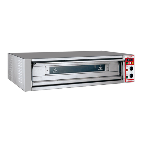
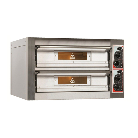
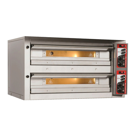
ZANOLLI TEOREMA POLIS PW Reference manual

DR. ZANOLLI s.r.l.
Via Casa Quindici, 22
37066 Caselle di Sommacampagna
(Verona) Italy
Tel +39 045 8581500 (r.a.)
Fax +39 045 8581455
Web: www.zanolli.it • e-mail: [email protected]
TEOREMA
POLIS PW
Manuale di installazione, uso e manutenzione
Manual for installation, use and maintenance
Manual de instalación, uso y manutención
Notice d’installation, d’utilisation et d’entretien
INSTALLATIONS-, BEDIENUNGS-UND INSTANDHALTUNGSHANDBUCH


cod. TPOPW.E.D.UK.15 - rev. 0.1 del 31/08/2016
TEOREMA POLIS PW
3
INDEX
1. PRESENTATION.................................................................................5
1.1. Use of Symbols.............................................................................5
2. TECHNICAL SPECIFICATIONS..........................................................7
2.1. Identifying the product...................................................................7
2.2. Conformity to European Directives ...............................................7
2.3. Intended use.................................................................................7
2.4. Technical specifications................................................................7
3. INSTALLATION...................................................................................8
3.1. Checking upon delivery.................................................................8
3.2. Choosing a place for installation...................................................8
3.3. Moving the unit ...........................................................................10
3.4. Positioning and mounting the unit...............................................11
3.5. Electrical connection...................................................................11
3.6. Emissions from cooking appliances............................................12
3.7. Checking before starting work ....................................................13
4. FUNCTION ........................................................................................14
4.1. Control Panel..............................................................................14
4.2. Inactive “OFF”.............................................................................15
4.2.1. Settings for clock, day of the week and language....................16
4.2.2. Activating / deactivating the hood key......................................16
4.2.3. System Reset...........................................................................17
4.3. Active “ON” .................................................................................17
4.3.1. Program settings......................................................................18
4.3.2. Programmed start settings.......................................................22
4.3.3. Chamber light key....................................................................24
4.3.4. Cooking cycle start / stop key ..................................................24
4.3.5. Activating / Deactivating the Economy function .......................24
4.3.6. Enabling / Disabling the Vaporizer ...........................................25
4.4. Alarms ........................................................................................26
4.4.1. Temperature probe fault alarm.................................................26
4.4.2. Power failure alarm..................................................................27
4.4.3. Vaporizer’s Water level alarm ..................................................28
4.4.4. Abnormal shutdown of the oven...............................................28
5. USE ...................................................................................................29
5.1. Preparation for use .....................................................................29
5.2. Turning on the control panel .......................................................29
5.3. Programming..............................................................................29
5.4. Starting cooking..........................................................................30
5.5. Loading the oven ........................................................................31
5.6. General guidelines for best results..............................................31
5.7. Turning off the equipment...........................................................32
5.8. Cleaning .....................................................................................32

cod. TPOPW.E.D.UK.15 - rev. 0.1 del 31/08/2016
TEOREMA POLIS PW
4
6. CLEANING........................................................................................33
6.1. Cleaning the exposed parts ........................................................33
6.2. Cleaning the parts made from ceramic refractory material..........33
6.3. Cleaning the oven’s cooking chamber ........................................34
7. MAINTENANCE.................................................................................35
7.1. Changing the halogen lamp........................................................35
7.2. Door Lubrication .........................................................................36
7.3. Tightness check of mains power connections.............................37
7.4. Control Panel cleaning................................................................37
7.5. Wiring diagram............................................................................38
7.6. Adapting to different power supply voltages................................38
7.6.1. Resistor rewiring......................................................................38
7.6.2. Applying the new label.............................................................38
8. DECOMISSIONING AND DEMOLITION...........................................39
TECHNICAL ANNEXES
A. Technical Specifications
B. Connections
C. Wiring diagrams
D. Exploded views

1. PRESENTATION
TEOREMA POLIS PW
5
1. PRESENTATION
This manual refers to the following TEOREMA POLIS PW cooking unit
models:
- 2/MC18
- 2/MC30
- 2S/MC18
- 3/MC30
- 3/MC18
- 4/MC30
- 4/MC18
- 6/MC30
- 6/MC18
The manufacturer would like to thank you for the preference expressed
in your purchasing this product. We can confidently assure you that it is a
good choice. Our company has been committed to the manufacture of
quality products for many years. We do not believe in making
compromises and use the best possible materials.
1.1. Use of Symbols
The paragraphs marked with this symbol contain indications
essential to safety. They must all be read both by installers, the end
user and any employees that use the oven. The Manufacturer does
not assume any responsibility for damage or injury incurred as a
result of ignoring the safety criteria outlined in these paragraphs.
This symbol applied to various points on the oven, serves to
warn the user of danger: “CAUTION, HOT SURFACES!”.
This symbol, applied to various points on the oven, serves
to warn the user of the presence of a non-insulated “high voltage
hazard” inside the oven’s casing, where there is enough power to
constitute a fire risk or to electrocute a person.
We recommend:
This manual consists of several chapters. They should be read in
their entirety by both installers and service personnel as well as by the
end user, to make sure that the equipment is used safely and to get the
best results from the product.

1. PRESENTATION
TEOREMA POLIS PW
6
It is recommended that this installation, instruction and service
manual be kept in close proximity to the equipment so that it can be easily
and quickly consulted. The manual must accompany the equipment if it is
resold, as it cannot be considered complete and safe without it.
Take note of the code and the manual version number shown on the
back cover. In the event that this copy is lost or destroyed, you can order
another copy using the above details.
The technical annexes contain features related to the specific oven
model and all values which may be necessary for the selection,
installation and use. This chapter should be used as a point of reference
to check that its intended use is in line with the way the machine has been
designed to operate and ensure that information concerning the precise
value of a given measurement or tolerance of the equipment is available
whenever necessary.
This chapter also provides a description of the electrical equipment that
comes with the machine, an exploded view of equipment and a list of
spare parts, to facilitate ordering and replacing any damaged parts.
The Manufacturer reserves the right to update production and
instruction manuals without having to update the previous production and
instruction manuals, if not under exceptional circumstances.

2. TECHNICAL SPECIFICATIONS
TEOREMA POLIS PW
7
- 2/MC18
- 2/MC30
- 2S/MC18
- 3/MC30
- 3/MC18
- 4/MC30
- 4/MC18
- 6/MC30
- 6/MC18
2. TECHNICAL SPECIFICATIONS
2.1. Identifying the product
This manual refers to the following TEOREMA POLIS PW cooking units,
models:
2.2. Conformity to European Directives
The TEOREMA POLIS PW cooking units, bear the following obligatory
marking:
Guaranteeing their conformity to the following European directives
2004/108/CE electromagnetic compatibility;
2006/95/CE low voltage;
1935/2004/CE Regulation for Equipment intended to come into Contact
with Foodstuffs.
2.3. Intended use
TEOREMA POLIS PW cooking units are designed for baking pastry
products, bread and pizza, and are intended for professional use by
qualified catering staff only.
The operations expected from normal use are: door opening and closing,
loading and unloading of products from the baking chamber, turning on,
regulating and turning off the oven and equipment cleaning.
2.4. Technical specifications
For technical specifications refer to the following technical annexes at the
end of this manual:
A. Technical Specifications
B. Connections
C. Wiring diagrams
D. Exploded views

3. INSTALLATION
TEOREMA POLIS PW
8
3. INSTALLATION
ATTENTION! These installation instructions are for the
exclusive use of personnel qualified in the installation and
maintenance of electrical equipment. Installation by unqualified
persons could cause damage to the oven, to people, animals or
property.
In addition, where modifications or adaptations need to be made to the
electrical systems in the building where the machine will be installed,
whoever carries out such modifications must certify that the work has
been undertaken according to current regulations in the country where it
is installed
3.1. Checking upon delivery
Unless otherwise agreed, the products are carefully bubble wrapped in
a robust wooden structure to protect against knocks and humidity during
transport, and are delivered to the carrierin the best condition.
We recommend, however, that you check the packaging on arrival for
any signs of damage. If there is damage, have it noted on the receipt
which must be signed by the driver.
Once the equipment has been unpacked, check that it has not suffered
damage. Also check that all the dissembled parts are present.
In the event of damage to the equipment and/or missing parts, bear in
mind that the carrier can only accept claims within 15 days of delivery and
that the manufacturer cannot be held responsible for damage incurred to
its products during their delivery. We are however, available to assist you
in presenting your claim.
In the event of damage do not try to use the equipment and
consult with professionally qualified personnel.
3.2. Choosing a place for installation
The appliance’s effective, safe and long lasting operation also
depends on the position in which it is installed. For this reason, it is
advisable to carefully consider where to install the equipment before it is
delivered.

3. INSTALLATION
TEOREMA POLIS PW
9
Fig. 4.1
Install the appliance in a dry and
easily accessible place both to
facilitate its use and to carry out
cleaning and maintenance. The area
around the equipment must be kept
clear. It is particularly important to
avoid obstructing the cooling outlets
located at the sides of the equipment.
When choosing a place to install the
“TEOREMA POLIS PW” cooking
units, bear in mind that they must be
completed with other units in the series:
hood, chamber, base.
The appliance must be installed at least 20cm from the walls
of the room or from other equipment so that the ventilation outlets
located on the sides of the oven are not obstructed.
Whilst in operation, the cooking equipment produces vapor and cooking
smells that compromise the integrity of a healthy working environment.
In the case of electric ovens, although not obligatory, the installation of
an extraction fan and hood is recommended to improve conditions in the
working environment and to avoid damage to the ceiling of the area where
it is housed caused by hot, oily fumes.
A check must be made to ensure that the temperature and relative
humidity never exceed the maximum and minimum values indicted in the
specifications (see Annex A) even when the oven itself or other ovens in
the room are functioning.
Exceeding the temperature or the maximum relative humidity values
can easily and unexpectedly damage electrical equipment creating
hazardous situations.
The manufacturer cannot answer for damage caused by
ignoring these abovementioned norms regarding the equipment’s
proper installation

3. INSTALLATION
TEOREMA POLIS PW
10
3.3. Moving the unit
To unload and transport the unit
while it is packed, a pallet truck or a
transpallet lifter with a load capacity
at least equal to that of the unit
should be used, inserting the forks
in the spaces provided at the base
of the packing.
To transport the module without
packing, use ropes or straps
(certified as suitable for lifting heavy
loads) threaded through the rings
on the top of the oven and lift with a
fork lift truck (Fig.1).
DO NOT raise the module by inserting forks or bars inside
the cooking chamber because this could damage the refractory
material at the top of the oven.
In all situations, to avoid unpredictable movement, be aware
of the equipment’s centre of gravity.
Take care that children do not play with the packaging
materials (e.g., plastic sheeting and Styrofoam): suffocation danger!
1

3. INSTALLATION
TEOREMA POLIS PW
11
2
3.4. Positioning and mounting the unit
1 - Position the module on the
base /cell/other unit, manoeuvring
it as described in paragraph 3.3
(Fig.2)
2 - Allow the four fixing
flanges on the corners of the
oven to drop into position (Fig.2)
3 - Secure with the screws
provided (Fig.2)
NO MORE THAN 3 UNITS
SHOULD BE STACKED ONE ON
TOP OF THE OTHER
When one or more units
is mounted on top of another,
use high heat silicone to seal
around the vapor exhaust tubes
at the back, at the point where they join.
3.5. Electrical connection
Before making any connection, check that the specifications of the
electrical supply to which the equipment must be connected, correspond
to the specifications of the power supply required by the apparatus itself
(see Annex A).
The appliances are supplied with an earthed electrical cable for
connecting the appliance to the power grid according to the supply
required (see Annex A).
In compliance with the safety norms in force, it is obligatory to
connect the ground/earth cable (yellow-green) to an earthing system
with the same dispersion capacity as the appliance itself. The
efficiency of this system must be correctly verified according to the
norms in force.

3. INSTALLATION
TEOREMA POLIS PW
12
The power cable must terminate with a plug to connect to the electrical
panel having a corresponding Residual Current Circuit Breaker with Over
Current Protection.
The equipment is not supplied with a power plug.
The coupling between plug and socket must be such that the earth
conductor is connected first and disconnected last and must have the
right dimensions for the rated current. Plugs and sockets for industrial use
of the type CEE17 are suitable or those which satisfy European norm EN
60309.
The thermal circuit breaker must be calibrated to the total rated current
and the magnetic circuit breaker calibrated to the rated current (In the
case of ovens this is only slightly higher than rated current), while the
differential device must be calibrated to the 30 mA current (see Annex A).
The electrical socket must be easily accessible and must not need moving
after equipment installation. The distance between the equipment and the
socket must be sufficient to avoid stretching the power cable
The power cable must never be trapped under the feet or
wheels of the equipment
If the Power cable is damaged it must be replaced by
customer support or by a qualified service engineer so as to avoid
any risk.
The manufacturer does not accept responsibility for damage
caused by failure to observe the abovementioned norms.
For the position of the electrical power connections, see Annex B.
3.6. Emissions from cooking appliances
ATTENTION! Proceed with the installation of the oven
according to the norms defined by current legislation in the country
concerning the installation of this type of oven so as to guarantee
the sustainability of a healthy working environment. For more
information it is recommended that specific norms be consulted.

3. INSTALLATION
TEOREMA POLIS PW
13
The Manufacturer cannot answer for damage caused by ignoring
these abovementioned norms as well as the information in this
manual.
To locate exhaust see Annex B
3.7. Checking before starting work
After completing installation of the unit a series of checks must be carried
out, listed as follows:
- check that the various disassembled parts have been assembled
- check the electrical power connections;
- check that the control panel is working
- If present, check that the ventilation hood is working
IMPORTANT –TURNING ON FOR THE FIRST TIME
The components of a factory new oven (cooking surfaces of refractory or
sheet metal material) need to be subjected to an initial preheating.
BRINGING THE OVEN UP TO TEMPERATURE OVER A PERIOD OF 5-
6 HOURS (1°h=100°C - 2-3°h=150°C - 4°h=200°C - 5°h=250°C -
6°h=300°C); the first time the oven is turned on this is an
INDISPENSIBLE procedure to avoid possible damage to the above
mentioned parts.

4. FUNCTION
TEOREMA POLIS PW
14
Cooking temperature
decrease Key
Cooking
timer
decrease Key
Overhead Power
decrease Key
Bedplate
power
decrease Key
Vaporization timer
decrease Key
Program n. decrease
Key
Program
saving
Key
Chamber light Key
General on/off
Economy function
Key
Cooking
temperature increase
Key
Cooking
timer
increase Key
Overhead Power
increase Key
Bedplate
power
increase Key
Vaporization timer
decrease Key
Program n. increase
Key
Cooking
cycle
start / stop Key
Vaporization Key
Hood Key
Program Key
Setting temperature /
chamber temperature
display
Cooking
Timer
display
Overhead
power
display
Bedplate display
Vaporisator display
Program display
4.FUNCTION
4.1. Control Panel
Keys
Display

4. FUNCTION
TEOREMA POLIS PW
15
System
Inactive
“OFF”
Active
“ON”
Clock and
language settings
Settings
Hood on Key
Programmed start
settings
System
Presetting
Cooking chamber
light
Cooking cycle
start
Economy mode
Vaporizer on
System summarychart
4.2. Inactive “OFF”
During the inactive mode “OFF” the –electronic- card is powered but
none of the functions required for the functioning of the system will be
activated since the general contactor is not on yet. The display has no
backlight and “OFF” followed by current date and time are shown.
During the inactive “OFF” mode you can:
-set the clock (12/24h mode, time, day) and the language;
-on / off the hood;
-carry out system preset.

4. FUNCTION
TEOREMA POLIS PW
16
4.2.1. Settings for clock, day of the week and language
Press and hold the “clock” key (Fig.1) for 3
seconds until a white backlit screen with the
following parameters is displayed (Fig.2):
- 12/24h = 12h or 24 hr mode
- 10:38 = hours and minutes
- LUNEDI (MONDAY) = day of the week
- ITALIANO (ENGLISH) = language
Use the increase and decrease keys next to
the figures you want to change (Fig. 2). To save
press the clock key (Fig. 1). The system will then
return to the inactive “OFF” state.
4.2.2. Activating / deactivating the hood key
To activate or deactivate the hood key, press
and hold the top two “increase and decrease
keys” simultaneously (Fig. 3). Use the
“increase and decrease” keys next to ON to
activate or deactivate the function.
If you select ON, the key activates Fig. 4 and its
led turns green (when on).
If you select OFF, the key will be deactivated
and its led will turn off (Fig. 4).
To save and quit press (the key) “P”.
1
2
3
4

4. FUNCTION
TEOREMA POLIS PW
17
4.2.3.System Reset
To reset the system press and hold the
“chamber light”. “P” and “Vapor” keys
(Fig. 5) simultaneously until the
screen displays a “hand” followed by
the acoustic signal.
Then press the on/off key (Fig. 6) to
reset the system.
WARNING: RUNNING THIS
PROCESS WILL DELETE AND
REPLACE ALL PROGRAMMED
DATA/SETTINGS WITH DEFAULT
SYSTEM VALUES.
4.3. Active “ON”
By pressing and holding the key
on/off for 2 seconds (Fig.7) the system
will now come “ON”, a white screen
(white backlighting) with the
manufacturer’s trademark and the
program version will be displayed for 3
seconds, after which the screen will
then display the parameters relative to
the program in use before it was last
turned off.
During the active mode “ON” you can (or it’s possible to):
-Run all settings and programs;
-Start a cooking cycle;
-Turn on/off the chamber light;
-Activate/deactivate the economy function /mode;
-Turn on/off the vaporizer.
5
7
6

4. FUNCTION
TEOREMA POLIS PW
18
4.3.1. Program settings
The system comprises 22 programs.
Select the program number to run
using the “data increase and decrease
keys” (Fig.1), where:
A = setting temperature
B = cooking timer
C = hob overhead resistance timer start
D = bedplate resistance timer start
E = vaporizer timer
F = program name and n°
- Program no. 00 (PRE-HEATING)
Program no. 00 has the function of pre-heating the oven.
Temperature and “fast” or “slow” heating modes can be set through the
“data increase and decrease keys”. The cooking timer is set to endless
and cannot be modified.
- Program no. 01 (MANUAL)
Program no. 01 has a “manual” function. With this program you can
modify temperature, overhead and bedplate power values anytime, also
within a cooking cycle.
NOTE: These values are saved automatically by the system.
- Programs from no. 2 to no. 20
Each (one) of these programs can be
modified and saved to the system by
setting preferred temperature values,
cooking time, bedplate and overhead
power and the vaporizer timer, see
the following example:
1) Select the program number you
wish/want to set up (Fig.3).
1
2
3

4. FUNCTION
TEOREMA POLIS PW
19
OVERHEAD
ELEMENT
Value
BEDPLATE
Value
Resistors time [s]
ON
OFF
0
0
0
45
1
1
5
40
2
2
10
35
3
3
15
30
4
4
20
25
5
5
25
20
6
6
30
15
7
7
35
10
8
8
40
5
9
9
45
0
[s] = seconds
Attention: the total duration of the resistors’/resistances’ starting cycle is 45 s
2) Modify the temperature using the data
increase and decrease keys (Fig.4).
3) Modify cooking time through the
“data increase and decrease keys”(Fig.5).
The programming range of the cooking
timer is between 1 minute and 24 hours.
NOTE: THE COOKING TIMER CAN
BE SET TO ENDLESS BY SELECTING
THE 4 DASHES ON THE DISPLAY
(VALUES BETWEEN 00 and 23 IN THE HOUR PARAMETER AND
BETWEEN 00 and 59 IN THE MINUTE PARAMETER).
4) Modify overhead and bedplate power
through the “data increase and decrease
keys (Fig.6).
NOTE: Each unit displayed on the
screen is equivalent to 5 seconds during
which the combined resistors/resistances
will remain on/active. Resistors/resistance
will remain off/inactive in the remaining units. The cycle has a total
duration of 45 seconds.
The start time value of the two resistances can be modified anytime by
the user, even during a cycle.
The following table shows timing combined with the starting values of
the overhead and bedplate resistances.
4
5
6

4. FUNCTION
TEOREMA POLIS PW
20
NOTE: BY SETTING BOTH THE OVERHEAD AND BEDPLATE
RESISTORS TO “0” THE OVEN WILL NOT HEAT.
NOTE: CHECK THAT CHOSEN OVERHEAD AND BEDPLATE
VALUES ARE APPROPRIATE TO THE SET COOKING CHAMBER
TEMPERATURE. BY CHOOSING LOW OVERHEAD AND BEDPLATE
START TIMES, THE SET CHAMBER TEMPERATURE MAY NEVER BE
REACHED.
5) Once the Vaporizer has been activated
(see 4.3.6), modify timer values with the
“data increase and decrease keys” (Fig.7).
The programming range of the
vaporization parameter is between 1
and 4.
Each value corresponds to a certain time
(seconds) of vapor emission:
value 1 = 2 seconds of vapor;
value 2 = 4 seconds of vapor;
value 3 = 6 seconds of vapor;
value 4 = 8 seconds of vapor.
6) Once setting is finished, save data by
pressing and holding the “P” key for 10
seconds until (you hear) the acoustic
signal (Fig.8).
7
8
Table of contents
Other ZANOLLI Kitchen Appliance manuals