74=7>!1?!4!@3A!
<"1"=0>/412"? i
31 74B(@2367(471?!4!@3A71CCCCCCCCCCCCCCCCCCCCCCCCCCCCD
Introduzione ......................................................4
A-1 Simbologia presente nel manuale .....................5
A-2 Assistenza .........................................................5
A-3 Datidiidenticazione ........................................6
A-3.1 Modello e tipo ....................................................6
A-3.2 Costruttore ........................................................6
A-3.3 Targhettadiidenticazione ................................6
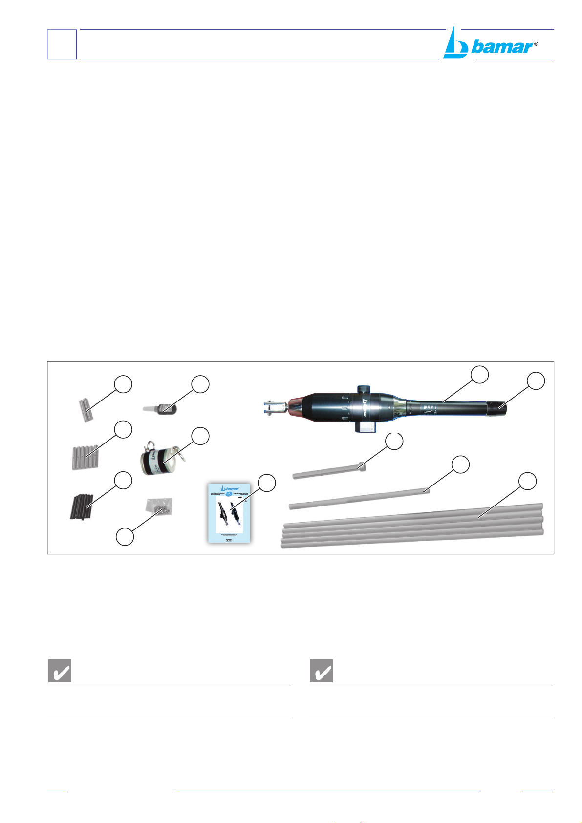
A-4 Imballoecontenuto ...........................................7
A-5 Ricevimentodelmateriale .................................7
A-7 Attrezzaturaminimanecessaria ........................8
A-8 Descrizionedell’apparecchiatura ......................8
A-9 Datitecnici .........................................................9
A-10 Impieghi ammessi ...........................................14
A-11 Uso improprio ..................................................14
E1 07>/@!6631CCCCCCCCCCCCCCCCCCCCCCCCCCCCCCCCCCCCCCCCCCCCCCCCCCCC.F
B-1 Indicazionigenerali .........................................15
>1 705@/67(471=712(453??7(1CCCCCCCCCCCCCCCCCCCCCCCC.G
C-1 Operazioni preliminari .....................................16
C-1.1 Consigli e note ................................................17
C-2 Tabelladi“TirodeiCilindriIdrauliciIntegrati”
negliavvolgioccoidraulicimod.GFI ..............18
C-3 Tabellariferimentorodecavi ..........................19
C-4 Determinazione della quantità e della
lunghezzadeiproli ........................................20
C-4.1 GFI12-12C ...................................................20
C-4.2 GFI16-16C ...................................................22
C-4.3 GFI25-25C/35-35C ...................................24
C-4.3.1BMG70(soloGFI25-25C) ...........................24
C-4.3.2BMG80-90-110 ...........................................25
C-4.3 GFI50C ...........................................................27
C-5 Schemaproloterminale,giuntiedistanziali ..29
C-6 Preparazionealmontaggioproli
BMG40R-50R ................................................30
C-6.1 Taglioamisuradelprolointermedio ..............30
C-6.2 Foraturadelprolo ..........................................31
C-6.3 Preparazionedelproloterminale ..................31
C-7 Montaggiodell’avvolgioccoconstralloaterra 32
C-7.1 Metodo di montaggio dei giunti e dei rinforzi ...32
C-7.2 Montaggiodelproloterminale .......................33
C-7.3 Montaggiodeiproliintermedi ........................34
C-7.4 Montaggiodellatestagirevole ........................35
C-7.5 Montaggiodell’adattatore ................................35
C-7.6 Montaggiodelproloinferitore ........................35
C-8 Preparazionealmontaggioproli
BMG52-60-70-80-90-110-125 ............36
C-8.1 Taglioamisuradelproloterminale ................36
C-8.2 Preparazionedelproloterminale ..................37
C-9 Montaggiodell’avvolgioccoconstrallo
a terra ..............................................................37
C-9.1 Metodo di montaggio dei giunti e dei rinforzi ...38
C-9.2 Montaggiodiproloterminale,giuntidi
rinforzo,distanzialiedanellodifermo .............39
C-9.3 Montaggiodeiproliintermedi .......................40
C-9.4 Montaggiodellatestagirevole ........................41
C-9.5 Montaggiodell’adattatore ................................41
C-9.6 Montaggiodelproloinferitore ........................42
0/ <"1"=0>/41@(=3054(1/AAAAAAAAAAAAAAAAAAAAAAAAAAAAAAAB
Introduction .......................................................4
A-1 symbols to be found in the manual ...................5
A-2 After-sales service .............................................5
A-3 Identicationdata ..............................................6
A-3.1 Model and type ..................................................6
A-3.2 Manufacturer .....................................................6
A-3.3 Identicationplate .............................................6
A-4 Packaging and content ......................................7
A-5 Receipt of goods ...............................................7
A-7 Basic tools .........................................................8
A-8 Description of the equipment ............................8
A-9 Technical data .................................................10
A-10 Proper use .......................................................14
A-11 Wrong use .......................................................14
C/ .0@"5D/AAAAAAAAAAAAAAAAAAAAAAAAAAAAAAAAAAAAAAAAAAAAAAAAAAAAAAAAAAEF
B-1 General indications .........................................15
6/ 41.50>>054(1/AAAAAAAAAAAAAAAAAAAAAAAAAAAAAAAAAAAAAAAAAAAAAAEG
C-1 Preliminary operations ....................................16
C-1.1 Suggestions and notes ....................................17
C-2 Load table of the Hydraulic Cylinders
integrated in the hydraulic furlers mod. GFI ....18
C-3 Reference sheet for rod and wire ....................19
C-4 How to determine quantity and length of foils .20
C-4.1 GFI 12 - 12C ...................................................20
C-4.2 GFI 16 - 16C ...................................................22
C-4.3 GFI 25 - 25C / 35 - 35C ...................................24
C-4.3.1 BMG 70 (GFI 25 - 25C only) ...........................24
C-4.3.2 BMG 80 - 90 - 110 ...........................................25
C-4.3 GFI 50C ...........................................................27
C-5 Terminal foil assembly scheme .......................29
C-6 How to prepare the foils BMG 40R -50R .........30
C-6.1 Cutting the middle foil to measure ...................30
C-6.2 Drilling the foil ..................................................31
C-6.3 Preparing the terminal foil ...............................31
C-7 Installing the furler with grounded stay ............32
C-7.1 Fitting splice pieces and half bearings ............32
C-7.2 Fitting the terminal foil .....................................33
C-7.3 Fitting the middle foils .....................................34
C-7.4 Fitting the halyard swivel .................................35
C-7.5 Fitting the tack adapter ....................................35
C-7.6 Fitting the hoisting foil .....................................35
C-8 How to prepare the foilS
BMG 52 - 60 - 70 - 80 - 90 - 110 - 125 ............36
C-8.1 Cutting the terminal foil to measure ................36
C-8.2 Preparing the terminal foil ...............................37
C-9 How to install the furler with grounded stay ....37
C-9.1 Fitting connectors and half bearings ...............38
C-9.2 Howtotterminalfoil,reinforcement
connectors,spacersandblockingring ............39
C-9.3 Fitting middle foils ...........................................40
C-9.4 Fitting the halyard swivel .................................41
C-9.5 Fitting the tack adapter ....................................41
C-9.6 Fitting the hoisting foil .....................................42
C-10 How to install the furler onboard .....................43
C-11 How to adjust the turnbuckle ...........................43
C-12 How to install the furler on armed mast ...........44
HUM_GFI_I-GB_rev. 2.0