Zaxcom QRX200 User manual

1
User Manual
Published August 2016
Software Version QR2-3.87
QRX200
The Ultimate in Receiver Flexibility

2
QRX200 RECEIVER............................................................................................................................. 4
FRONT ......................................................................................................................................................................4
REAR ........................................................................................................................................................................5
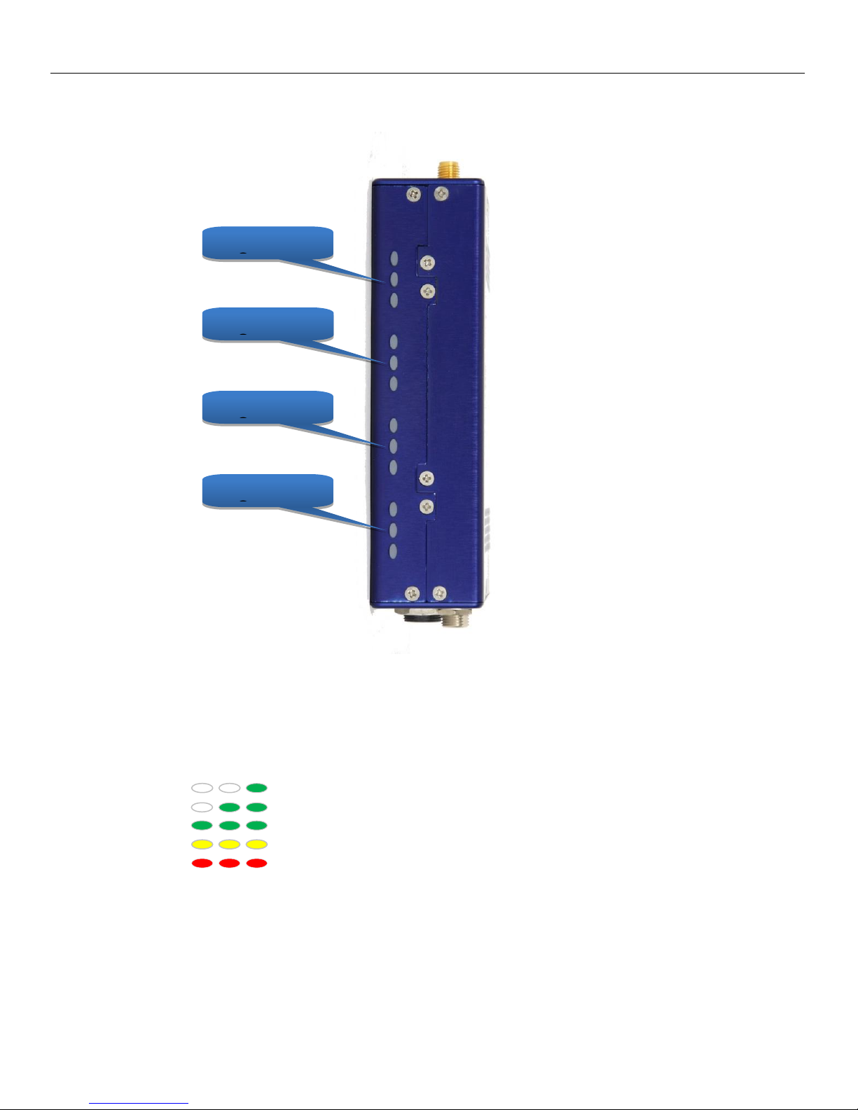
SIDE .........................................................................................................................................................................6
HOME SCREEN.................................................................................................................................. 7
MAIN MENU..................................................................................................................................... 8
NAVIGATING THE MAIN MENU .....................................................................................................................................8
EXITING THE MAIN MENU............................................................................................................................................ 8
FREQUENCY ADJUST....................................................................................................................................................8
Adjusting the receive frequency of the QRX...................................................................................................... 8
THE >WILL INDICATE THE RECEIVER BEING ADJUSTED........................................................................................................8
TRANSMITTER GAIN ADJUST .........................................................................................................................................8
Adjusting the transmitter gain remotely ........................................................................................................... 8
UNIT CODE SELECT .....................................................................................................................................................9
TEST TONE OUTPUT ....................................................................................................................................................9
FREQUENCY SCAN.....................................................................................................................................................10
Single mode scanning ......................................................................................................................................10
Selecting a frequency....................................................................................................................................... 10
Dual mode scanning......................................................................................................................................... 10
SET SCAN RANGE......................................................................................................................................................11
EXTENDED MENU ........................................................................................................................... 12
NAVIGATING THE EXTENDED MENU.............................................................................................................................12
EXITING THE EXTENDED MENU ...................................................................................................................................12
MODULATION SELECT................................................................................................................................................12
SINGLE /DUAL MODE SELECT.....................................................................................................................................12
AES OUTPUT ENABLE................................................................................................................................................13
OUTPUT ASSIGNMENT...............................................................................................................................................13
TRANSMITTER REMOTE CONTROL ENABLE ....................................................................................................................13
SERIAL PORT ASSIGN .................................................................................................................................................13
OUTPUT ROUTING ....................................................................................................................................................14
QRX SOFTWARE UPDATE .....................................................................................................................................14
AES RECOGNIZE....................................................................................................................................................14
AES OUTPUT SAMPLE RATE ADJUST.......................................................................................................................14
LED BRIGHTNESS SET ............................................................................................................................................15
BLUE LED SET........................................................................................................................................................15
ENCRYPTION CODE SET ........................................................................................................................................15
Adjusting the encryption code......................................................................................................................... 15
FREQUENCY PRESETS ............................................................................................................ 16
FIRMWARE ................................................................................................................................. 17
UPDATING THE QRX SOFTWARE USING A TRX TRANSMITTER...............................................................................17
WIRING DIAGRAMS ................................................................................................................. 18
AUDIO OUTPUT CONNECTORS.............................................................................................................................18
Single Analog Channel out of one TA5 ...........................................................................................................18
Two Analog Channels out of one TA5 ........................................................................................................... 18

3
AES Digital out of TA5 .................................................................................................................................... 18
SERIAL LOOP CONNECTOR -USB (RS-485)...........................................................................................................19
OPERATING FREQUENCIES .................................................................................................. 20
ZAXNET REMOTE CONTROL AND TIME CODE ......................................................................................................20
UHF AUDIO ..........................................................................................................................................................20
ANTENNA CUTTING CHART................................................................................................ 21
SPECIFICATIONS...................................................................................................................... 22
PRODUCT SUPPORT ............................................................................................................... 23
ZAXCOM WARRANTY POLICY AND LIMITATIONS ....................................................... 24

Zaxcom QRX200 Front
4
QRX200 Receiver
Front
1. OLED Display
2. INC Key - Used to increase the parameters of a menu item.
3. UHF Antenna Connectors (2) - SMA connectors.
4. Dec Key - Used to decrease the parameters of a menu item.
5. Menu Key - Press to advance to the next menu item.
6. Receiver Status Indicators
Green - Receiver is receiving a valid signal.
Red - Receiver is not getting a valid signal.
7. A/B Key - Press to alternate between receivers in dual mode.
8. Power Key - Press and hold for 2 seconds to power up the QRX. Press and hold for 5 seconds to power
down the QRX.
2
4
1
3
5
6
7
3
8

Zaxcom QRX200 Rear
5
Rear
1. DC Power Input - The QRX uses a Switchcraft 761K connector.
2. Audio out connectors (2) - TA5M.
These connectors will output the audio from the QRX. The same connectors can be used to output
either analog audio or AES audio. The audio assignments for the TA5 connectors are set in the
extended menu.
3. Serial Loop -The USB style connectors on the back of the QRX allow multiple QRXs to share a single
common QIFB option. For example one master QRX with a QIFB option board can be connected to 3
QRXs with no option boards. The QRXs without option boards will behave as if they have an IFB option
board and will send remote control commands over the serial link to the master QRX.
Please note the USB connectors are NOT generic USB connectors that can be used as a connection to any
computer. These are used to exchange RS-422/RS-485 commands and a special cable is required to do
this please see the wiring diagram section of this manual for more information.
3
2
1

Zaxcom QRX200 Side
6
Side
Side Mounted LEDs - The LEDs give visual indication if RF and / or audio are being received by the QRX.
The LED settings are adjusted in the extended menu. There are three LEDs per group and one group for
each receive channel. The group to the top represents channel one, the group below is channel 2, the
next group is channel 3, and the group on the bottom is channel 4.
LED modulation colors
When the signal hits -40 dBFS
When the signal hits -20 dBFS
When the signal hits -10 dBFS
When the signal hits - 8 dBFS
When the signal hits - 5 dBFS
Channel 1
Group
Channel 2
Group
Channel 3
Group
Channel 4
Group

Zaxcom QRX200 Home Screen
7
Home Screen
Receiver
The QRX has two individual receivers the A (left receiver) and the B (right receiver).
Audio level
Indicates the incoming audio level for each receiver, the meter extends from the left to the right. The vertical
bar to the right is the -20dBFS mark.
Transmitter’s battery level
The battery diagram displays the transmitter’s battery level. The battery type being used in the transmitter needs
to be set in the TRX extended menu. The battery symbol will start to blink just before transmitter shuts down.
Transmitter’s record status
S (STOP) The transmitter is stopped.
R (REC) The transmitter is recording.
P (PLAY) The transmitter is playing back.
Receiving antenna
Indicates the signal is being received by antenna 1 (left antenna connector)
Indicates the signal is being received by antenna 2 (right antenna connector)
RF signal strength
This shows the radio signal strength of the corresponding TRX transmitter. The RF signal is depicted as a staircase
pattern with the lowest step (low signal strength) on the left and building up as it progresses to the right (higher
signal strength). When more stairs are showing the stronger the signal is.
AS
BS

Zaxcom QRX200 Main Menu
8
Main Menu
Navigating the Main Menu
To enter the main menu - press the MENU key.
To advance to the next menu press the MENU key again.
Exiting the Main Menu
To exit the main menu at any time press and hold the MENU key for 1.5 seconds.
Frequency Adjust
The menu is where the QRX’s receive frequency is set. This frequency needs to match the frequency that is set on
the corresponding transmitter.
Adjusting the receive frequency of the QRX
Press the INC key and DEC key to adjust the frequency.
In dual receive mode pressing the A/B key will toggle between the A and B receiver.
The > will indicate the receiver being adjusted.
Please note that when in dual receive mode the A and B frequencies needs to be within 35MHz of each other. If
the frequency difference is more than 35MHz “TOO BIG” or “TOO SMALL” will flash on the screen to warn that
the difference is greater than 35MHz and the frequency will need to be adjusted.
Transmitter Gain Adjust
This menu is only available when transmitter remote control is set to “ON” in the extended menu.
When a QRX100 or QRX235 with an IFB option board is connected via the serial loop, the gain of the corresponding
transmitter can be remotely adjusted from this menu. The transmitter gain menu will display the gain level and an
audio meter with a -20dBFS and -10dBFS mark on the right.
Adjusting the transmitter gain remotely
Press the INC key to increase the transmitters gain. As the gain is increased“+ + +” will replace the gain level.
Press the DEC key to decrease the transmitters gain. As the gain is decreased “- - -” will replace the gain level.
When in dual mode pressing the A/B key will toggle between the two transmitters.
TX A 24
GAIN
CH A> 567.4
CH B 570.0

Zaxcom QRX200 Main Menu
9
Unit Code Select
This menu is only available when transmitter remote control is set to “ON” in the extended menu.
This menu sets the unit code that will correspond to the transmitter that is being controlled. The unit code is a
unique number used to identify a transmitter within a particular group. This allows individual transmitters that are
within the same group to be independently controlled. Unit codes can be any number from 1 to 200.
Test Tone Output
From this menu 1K tone can be enabled. That tone will be outputted from the TA5 connectors. This is used to
set levels and check routing.
Pressing the INC and DEC key will cycle through the different tone settings.
OFF - No tone is being outputted.
-20dBFS -Tone is simultaneously sent to all 4 outputs at -20dBFS.
CHAN-ID -Tone is sequentially sent to each channel one at a time at -20dBFS.
+0dBFS - Simultaneously sends tone to all 4 channels at 0dBFS (full scale)
RXA UNIT: 1
RXB > UNIT: 2
TONE:
OFF

Zaxcom QRX200 Main Menu
10
Frequency Scan
The frequency scan menu is where the QRX can scan the specified frequency range to search for a clear
frequency. After a scan a graphical display of the RF that is present, in that specified range, will be shown.
Single mode scanning
Turn off the transmitter.
Press the INC key to initiate a scan.
As the block is being scanned, the frequency being examined is
displayed on the bottom half of the screen and a graphic map of the RF
that is found will be displayed with a vertical line extending up from the
baseline. The length of the line indicates the level or strength of the
found RF at that frequency.
Selecting a frequency
When the scan is complete a suggested frequency will be shown and a
vertical blinking line will be drawn on the display.
At that point:
Press the INC key to accept the frequency.
Press the A/B key or the DEC key to suggest another frequency.
Dual mode scanning
In dual mode the two operating frequencies must be within 35MHz of
each other. Pressing the INC key will scan the full chosen scan range
(scan range is set in the next menu) and recommend a frequency from
the entire range. If a second frequency is being chosen to work with a
previous chosen frequency, press the DEC key to limit the scan to a
70MHz window which is 35MHz above and 35MHz below the other
selected frequency. After a scan is triggered, by either pressing INC or
DEC key, the QRX will scan and suggest a frequency. After the scan is
completed that frequency can be accepted or rejected the same way as in single mode. If an exclamation point
appears after the suggested frequency that is a warning that the shown frequency is more than 35MHz away
from the other frequency. That frequency can be selected provided a new frequency that is within 35MHz of
this frequency will be selected for the other receiver. After the first scan turn on the first transmitter and set it
to the chosen frequency, this way when the scan is performed for the second transmitter the QRX will not
select the same, or adjacent, frequency. To toggle between scanning RXA and RXB press the A/B key.
PRESS TO SCAN
ALL 200: 512 - 698
SCANNING 568.9
TAKE 618.2
PRESS TO SCAN
ALL 200: 512 - 698
RX B
TO LIMIT SCAN
ALL 200: 512 - 698
RX B

Zaxcom QRX200 Main Menu
11
Set Scan Range
This menu sets what frequency range will be examined when doing a frequency scan. Press the INC and DEC key
to cycle through the scanning options.
Available Scan Ranges
All 200 - All frequencies from 512.0MHz through 698.0MHz will be scanned.
LO 100 - Corresponds to the frequency range of TRX3.5 transmitters, when selected frequencies from
512.0MHz through 614.0MHz will be scanned.
HI 100 - Corresponds to the frequency range of TRX3.6 transmitters, when selected frequencies from
596.0 through 698.0MHz will be scanned
BLK (20 –26)- choose to scan a specific block (Blocks 20-26).
Block 20 518-542 MHz
Block 21 536-572 MHz
Block 22 560-590 MHz
Block 24 614-644 MHz
Block 25 638-668 MHz
Block 25 662-698 MHz
SCAN LIMIT
ALL 200 512 - 698

Zaxcom QRX200 Extended Menu
12
Extended Menu
Navigating the Extended Menu
Press and hold the DEC key from the home screen to enter the extended menu.
To advance to the next menu press the MENU key.
Press and hold the MENU key at any point to return to the top of the extended menu.
Exiting the Extended Menu
To exit the extended menu - press the POWER key briefly.
Modulation Select
This menu selects the modulation mode the QRX will receive. This setting needs to match the modulation
mode that the corresponding transmitter is set to - if the two setting do not match the QRX will not be able to
receive and decode the signal from the transmitter. Please note the QRX will need to be rebooted after a
change is made to the modulation.
STEREO
MONO
XR
ZHD 96
ZHD 48
Modulation Bandwidth
200 kHz
200 kHz
200 kHz
96 kHz
48 kHz
Minimum Channel to Channel Spacing
400 kHz
400 kHz
400 kHz
200 kHz*
100 kHz**
6 MHz TV Channel Capacity
15
15
15
30
60
Latency
6ms
3.5ms
6ms
6ms
18ms
Compatibility with a 200 Series Receiver
2 Transmitters
2 Transmitters
2 Transmitters
2 Transmitters
1 Transmitter
Compatibility with a 300-96 Receiver
NO
NO
NO
1 Transmitter
1 Transmitter
Compatibility with a 300-48 Receiver
NO
NO
NO
NO
1 Transmitter
* When used with a QRX300-96 receiver –the minimum spacing is 300 kHz when using all other receivers.
**When used with a QRX300-48 receiver –the minimum spacing is 200 kHz when using all other receivers.
Single / Dual Mode Select
SINGLE - This configures the QRX to operate as a single receiver. In single mode the QRX can receive one audio
channel from a mono transmitter or two audio channels from a stereo transmitter.
DUAL - This configures the QRX to operate as two independent receivers. In dual mode the QRX can receive
two audio channels from two mono transmitters, three audio channels from one stereo and one mono
transmitter, or four audio channels from two stereo transmitters.
RX MODE:
SINGLE
RX FMT: ZHD96

Zaxcom QRX200 Extended Menu
13
AES Output Enable
This menu enables the TA5 connectors to output an AES signal.
ON - Indicates that the TA5 will output AES audio.
OFF - Indicates that the TA5 will output analog audio.
Output Assignment
This menu is only available when the QRX is set to dual receive mode.
This menu sets what audio is outputted from each TA5 connector when the QRX is set to dual mode receiving
mono transmitters.
SPLIT / NORMAL - The signal from each transmitter will be outputted on individual TA5 connectors.
Transmitter 1 will be outputted on TA5 1 and transmitter 2 will be outputted on TA5 2.
COMBINED / SWAP -The signal from each transmitter will be combined on a single TA5 connector
Transmitter 1 and 2 will be combined on a single TA5.
Transmitter Remote Control Enable
Transmitter remote control turns on the ability to remote control the corresponding TRX transmitter when
connected to a QRX235, via the serial loop. The QRX200 will have the ability to remotely change the gain and
UHF frequency of the transmitter. Please note that the QRX235 will need to have an QRX option board installed.
Serial Port Assign
This menu sets the function of the serial port on the QRX.
OFF - No commands will be communicated to the serial port.
ZAXLAN QRX - The QRX will communicate commands to a QRX235, with QIFB, via the serial port.
BLUE TOOTH - This setting allows a QRX235 with QIFB will interface to communicate with a ZaxMote blue
tooth dongle via the serial port.
AES - 1 2: ON
AES - 3 4: OFF
AES OUTPUTS
NORMAL
SERIAL PORT
ZAXLAN QRX
TXREMOTE CTRL:
OFF

Zaxcom QRX200 Extended Menu
14
Output Routing
This menu is only available when the QRX is set to single receive mode.
This menu sets the output assignments of the TA5 connectors when the QRX is set to single mode and is
receiving a signal from a stereo transmitter.
QRX Software Update
This menu initiates a software update for the QRX. After the INC key is pressed the QRX will wait for software to
be sent from a TRX transmitter. When the QRX receives the software the update process will automatically
begin. Please note the QRX needs to be set to mono modulation and in single mode to update the software.
AES Recognize
The AES recognize is used for some Sony F5 or F55 cameras that cannot recognize the AES signal from the QRX.
OFF - The QRX will output a normal AES signal.
ON: AB KEY - This setting will send a special signal to the AES out, when the A/B key is pressed. This will allow
the Sony camera to recognize and lock to the AES signal from the QRX. This is the recommended setting.
ON: ALWAYS - The QRX will constantly send a special recognize signal via the AES out.
AES Output Sample Rate Adjust
This menu adjusts the AES output sample rate.
Normal -This is the recommended setting.
96K - The QRX will output a 96 kHz AES signal for some mixers like the Yamaha 01V that cannot properly
sample rate convert the AES signal.
PRESS TO
UPDATE SOFTWARE
OUTPUT ROUTING:
C1 =L C2 =R
OUTPUT ROUTING:
C1 = LR
The left output will be on TA5 connector 1 and
the right output will be on TA5 connector 2
Both the LEFT and RIGHT outputs will be on
both TA5 connector 1 and TA5 connector 2
SONY F5 AES
OFF (NORMAL AES)
AES OUTPUT RATE
NORMAL

Zaxcom QRX200 Extended Menu
15
LED Brightness Set
This menu sets the brightness level of the side mount LED’s.
OFF - The LEDs do not illuminate.
Numeric Value - Adjustable brightness levels.
Bright - The LED’s will illuminate at the brightest setting.
Blue LED Set
This menu sets the action of the bottom LED in each group (total of 4 groups).
The side mount LEDs were designed to give visual confirmation that audio is being received at the QRX. This
menu gives the option to display that a valid RF signal is getting to the QRX even if no audio is being sent.
OFF - The bottom LED will only display the audio modulation and the blue LED is disabled.
BLUE FULL TIME - Turns the bottom LED blue for each channel that is receiving a valid RF signal. When the
audio has gotten to the point of displaying a level for that channel, the bottom LED will continue to show blue
but with a tint of the appropriate modulation color of that channel’s LEDs.
BLUE PART TIME - Turns the bottom LED blue for each channel that is receiving a valid RF signal. Once the
audio is received, the blue is replaced with the appropriate modulation color for that channel.
Encryption Code Set
The encryption menu is where the encryption is turned on and the code is set. The encryption code needs to
match the encryption code of the associated transmitters. If an encryption code is set on the transmitter the
transmitted audio will be encrypted and can only be listened to if the QRX has the same matching encryption
code entered. When the codes do not match, all that will be heard is white-noise.
These two sets of numbers are formed into a single six-digit encryption code which provides a total of
16,777,216 possible combinations. For non-encrypted operations all six numbers should be set to 0.
Adjusting the encryption code
1. Press the A/B key to advance to the next character.
2. To change the designated character, press the INC or DEC key.
3. To exit this page, press and hold the MENU key.
.
LED DIMMER:
OFF
LED METER MODE:
OFF
ID1: 000 ID0: 000

Zaxcom QRX200 Channel Presets
16
Frequency Presets
The QRX has 16 user assignable frequency presets.
Access and navigating the channel preset menu:
From the home screen press and hold the DEC key for 1.5 seconds which will access the extended menu,
then press the DEC one more time to access the channel preset menu.
When in the channel preset menu pressing the MENU key will cycle through the 16 presets (0 through 15).
To adjust each preset frequencies press the INC and DEC key.
To advance to the next preset press the MENU key.
To exit the preset menu briefly tap the PWR key.
Selecting preset frequencies:
From the frequency adjust menu press and hold the DEC key until the QRX frequency reaches the minimum
frequency of 512.0MHz. Then continue to press the DEC key to access the 16 preset frequencies.
Pressing the INC and DEC keys will cycle through the 16 preset frequencies.
CHANNEL PRESETS
PRESET 1: 543.0

Zaxcom QRX200 Firmware Update
17
Firmware
Each unit is shipped with the latest firmware version installed.
Each time a unit is powered up, the firmware version number is displayed briefly on the screen. Pressing the DEC
key during the boot up will slow down the screen to allow easier viewing of the information.
As newer firmware becomes available, it can be downloaded from the Zaxcom website:
http://www.zaxcom.com/software-updates
Updating the QRX software using a TRX transmitter
1. Format a micro SD card in a TRX transmitter.
2. With a computer take the formatted card and perform the following:
Delete the “SNXXXX.ME” file from the card.
Download the new QRX software and load it into the card. (QR2-XXX.BIN)
3. Insert the card and a fresh set of batteries into the TRX transmitter.
4. At the QRX:
Verify the QRX is set to single mode and modulation is set to mono.
Verify encryption is off (ID1 and ID0 are both set to 000)
Set the UHF Frequency to the same frequency as the programming transmitter.
The QRX receiver status LEDs should both be green.
From the extended menu go to the software update page and press the INC key.
The screen will display waiting for program. This indicates the receiver is ready to download the new
software. This can be done to several QRXs so they will be updated at the same time.
5. At the transmitter proceed to the setup menu proceed to the software update menu (see TRX manual) and
press the INC key.
6. Each QRX should indicate it is receiving the program.
7. After the software send cycle, all of the receivers should be re-programmed and “SUCCESS . . . REBOOT
NOW” will be displayed. If there was a reception error, the affected receiver will automatically restart the
process with the start of the next send cycle.
8. Reboot the QRX and verify the QRX is running the new software version.
WARNING: After the QRX has received its entire program, it will erase and burn its firmware into the ROM.
During this process, which only takes a few seconds, you MUST NOT turn ‘OFF’ the QRX. If the program is never
fully received, it is safe to cycle the power.

Zaxcom QRX200 Wiring Diagrams
18
Wiring Diagrams
Audio Output Connectors
There are two TA-5M connectors on the back panel. How they are used varies based on the output configuration
in the extended menu.
Single Analog Channel out of one TA5
TA5 out on
QRX
XLR into Camera or
Mixer
PIN 1
PIN 1
PIN 2
PIN 2
PIN 3
PIN 3
PIN 4
No Connection
PIN 5
No Connection
Two Analog Channels out of one TA5
TA5 Out on
QRX
XLR into Camera or
Mixer
PIN 1
PIN 1 on both XLRs
PIN 2
PIN 2 - Left
PIN 3
PIN 3 - Left
PIN 4
PIN 2 - Right
PIN 5
PIN 3 - Right
AES Digital out of TA5
The TA-5 connectors can also be used to output AES digital audio. Each TA5 will output a stereo pair on pins
1, 2 and 3 with pin 1 being ground.
When receiving audio from a mono transmitter the QRX will output the same audio on both pairs of the
TA5. When receiving audio from a stereo transmitter the QRX can output both signals on a single TA5.
IMPORTANT: While sending digital audio, it is necessary that the unit on the other end (recorder, mixer, etc.)
have digital inputs with sample rate convertors, as there is no way to synchronize the output data with the
recorder’s digital input.
TA5 out on
QRX
XLR into Camera or
Mixer
PIN 1
PIN 1
PIN 2
PIN 2
PIN 3
PIN 3
PIN 4
No Connection
PIN 5
No Connection

Zaxcom QRX200 Wiring Diagrams
19
Serial Loop Connector - USB (RS-485)
The serial connectors allow for communication between several QRXs. This allows QRXs that do not have the IFB
option to connect to a single QRX that does have the IFB option.

Zaxcom QRX200 Operating Frequencies
20
Operating Frequencies
ZaxNet - Remote Control and Time Code
2.403 to 2.475 GHz
UHF - Audio
512.0 MHz to 698.0 MHz (Blocks 20 through 26)
Other manuals for QRX200
1
Table of contents
Other Zaxcom Receiver manuals