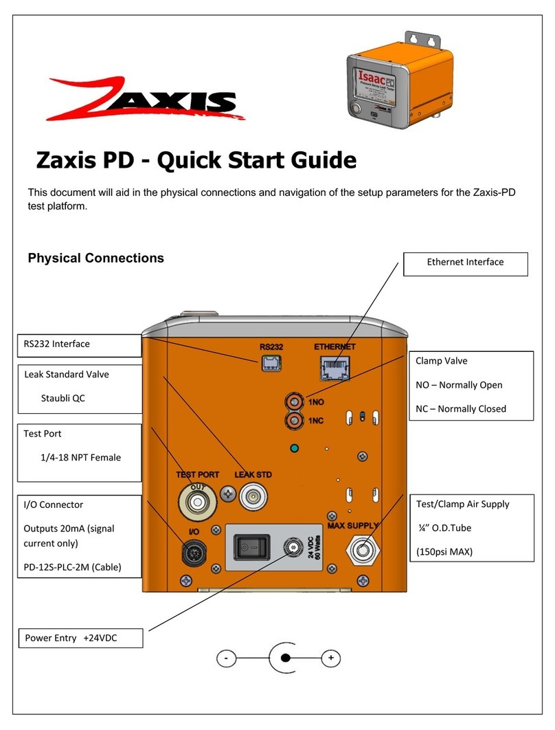
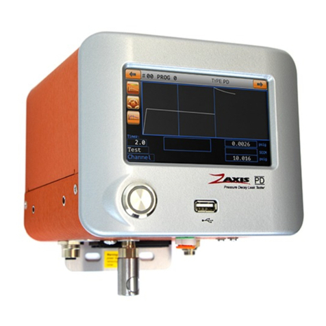
Zaxis Isaac HD User manual

1
User’s Guide
Ver. 2.01

2
This page has been left blank intentionally.

3
For Your Safety
Install all equipment according to local safety codes.
Here are some additional safety guidelines when working with the Isaac or iKit leak tester:
➢Wear eye protection when working with compressed gas.
➢Beware that hazardous voltages could be present inside the enclosure.
➢Only when you understand the procedure and you know exactly how to complete the task should
you attempt any maintenance procedure discussed in this guide.
Warning! Disconnect power before removing cover or fuse holder
Caution! Equipment requires clean-dry supply air. Non-compliance may void warranty.

4
THREE YEAR LIMITED WARRANTY
Zaxis, Inc. Limited Warranty
ZAXIS INC. products are manufactured to a very high standard, however when located in physically hostile
environments or when operated under non-specification voltage or pressure conditions, warranty may be
voided. Please refer to your user manual for more detailed information.
ZAXIS INC., therefore, warrants only as follows: Supply clean dry air only to the unit.
Each unit is identified by serial number in a permanent record of the company. If at any time with-in three
years after any ZAXIS INC. product has been shipped to a customer (user), it fails to perform according to
ZAXIS INC. literature, the product, with written explanation of the problem, may be returned, freight prepaid, to
ZAXIS INC. for examination, repair or replacement at ZAXIS INC. expense (labor and material). All such returns
must have prior ZAXIS INC. customer service authorization before returning. If, upon examination, ZAXIS INC.
determines that abusive practices, non-filtered and dried air or destructive environment of operation or a
combination of these factors is responsible for improper performance of the product, all labor and materials
costs involved shall be at the expense of the customer.
ZAXIS INC. is not liable for special, indirect or consequential damages that may result from use, failure or
malfunction of the product and any recovery against ZAXIS INC. may not be greater than the purchase price
paid for the product.
No person is authorized to change the terms of this warranty.

5
Introduction:
The Isaac HD Multi-Function Leak Tester is the newest product from Zaxis, designed to meet
today’s quality assurance demands.
The compact size of the Isaac enables it to be used in close proximity to fixtures and
operators utilizing a small footprint of bench top space. By reducing the internal and connection
volume the test sensitivity increases and test times can be decreased. The small internal volume
combined with integrated sensors and a 24bit analog to digital converter allow Zaxis to offer a
leak tester with the highest sensitivity on the market. The Isaac is available for pressure or
vacuum decay, mass flow, burst, pressure cracking, sealed component (chamber), and custom
test sequencing applications. The Isaac can be configured from one to four test channels in a
sequential or concurrent configuration depending upon applications.
This guide covers the standard Isaac HD and i-Kit HD leak testers. All of
the current functions and features are described in this manual. Your
tester could differ in installed features. Check the additional test types
section of this guide for application notes about your tester.
Safety and Emissions:
Operating Environment Conditions:
Indoor use only
▪Operating temperature range: 5-40° C
▪Maximum relative humidity: 80%
▪Main supply voltage: 120 V +/-10%, 2A ~ 60 Hz
Or 230 V +/-10%, 2A ~ 50Hz
▪Altitude: up to 2000 meters
▪Supply Air Pressure: 8.3 bar max. (unless otherwise specified)
Supply air must be clean and dry.
(10 micron filtration minimum, 5 micron recommended)
Physical Description:

6
Font Panel
1. Touch Screen Interface (TSi) - The liquid crystal touch screen display is the primary
control of the leak tester.
2. Abort Button / Fail Indicator Light / Retest Button - Red LED indicator marked with
an ‘X’.
3. Start Button/Pass Indicator Light - Green LED indicator marked with a ‘√’.
4. Test Ports - Each port is a 1/8”-27 F NPT (similar to R1/8 BSPT British Standard Pipe
Taper) female threads. This is where the DUT (device under test) is attached. Test port
positioning will vary by model.
5. Tilt-up feet –The position of the tester can be raised by rotating the tilt-up feet into
position. Units with the Electronic Regulator option will have these feet removed due to
the position sensitivity of the electronic regulator.
1
2
3
4
5

7
Rear Panel
1. Foot Switch Connector: For starting a test. Any closed contact switch may be used to start a test by
shorting pins 1 & 3
Mating Conn. & Pins –Tyco Electronics 1-480305-0 (Digi-Key A1400-ND), 60618-1 (Digi-Key A1422-ND)
2. Serial Output: Connection for interfacing Isaac to computers or printers. (Wiring)
3. Option Space: This space is used for Clamping (pneumatic outputs) or I/O connection
(shown)((Wiring))
If the I/O space is filled clamps will be in the secondary air connection location.
4. Pressure Regulator: Controls the air pressure applied to the product under test.
5. Power Entry Module: This component includes the power cord socket, on/off switch, and the fuse
holder. Power entry is capable of a range of 109-255~VAC. 2A Fuse (Service instructions)
6. Secondary Air Connections:These positions have multiple uses; Flow control for ramping burst/crack
pressure, coupling or pilot air entry, or secondary test air supply. See the Quick Start shipped with the
tester for details.
7. Supply:(Air or other test gas) Connection is 1/8”-27 F NPT (Similar to R1/8 BSPT British Standard Pipe
Thread) Supply gas must be clean and dry.
8. Ethernet Connector:ASCII communication, data output and command string input.
Additional items may be installed on the rear panel, see the quick start guide
shipped with the tester for additional details.
1
2
3
4
5
6
6
7
8

8
i-Kit rear panel
1. Power Entry Connector, Supply is 24VDC 60watts
(Mating connector S760K-Switchcraft)
2. Power Switch
3. Rear Test Port (optional)
4. I/O Interface Connection (Wiring Chart)
5. Test Pressure Supply, (Air or other test gas) Connection is 1/8”-27 F NPT (Similar to R1/8 BSPT British
Standard Pipe Thread) Supply gas must be clean and dry.
6. RS232 connector (Mate Supplied, wiring chart)
7. TSi, Touch Screen Interface Connector, the i-kit can be operated with or without the TSi attached.
8. Ethernet Port, ASCII communication, data output and command string input.
9. Footswitch connector, For starting a test. Any closed contact switch may be used to start a test by
shorting pins 1 & 3.
Mating Conn. & Pins –Tyco Electronics 1-480305-0 (Digi-Key A1400-ND), 60618-1 (Digi-Key A1422-ND)
5
3
4
2
9
8
7
6
1

9
Control Screens:
Buttons at the bottom of the TSi display allow the user to navigate through the setup screens.
(Run Mode)–Press this button to change to the run mode, to begin
testing.
(Program)- The program screens contain the parameters of the test
(timers and Limits), the number of channels being tested, and the clamp valves timer
configuration.
(Units)- Engineering units and the displayed sensor resolution.
(Calibrate)- Access to the calibration of Pressure, Vacuum, and Flow
Sensors.
(Options)- The menu screen has eight options: (1) Touchscreen
Calibration (2) Clock (3) I/O Setup (4) Data Logging (5) Lock tester (6) Change PIN (7)
Serial Port (8) Ethernet Settings. Each screen is described later in the setup section.
(About)- The “About” screen lists the firmware revision level for the TSi and
Isaac, serial number, as well as contact information for Zaxis.

10
Data input
Two input screens are used throughout Isaac’s setup and operation; they are the
Numeric and Alpha-Numeric Keypad screens. The Numeric Keypad screen is used to input
values for timer and limit fields. The Alpha-Numeric Keypad screen is used in fields such as the
program name field.
Examples of each are shown below.
Run Mode
Note:
Pressing the ‘shift’ key
changes the case.

11
There are two run screens available to choose from: Large Numeric( single channel), Large
Numeric (multi-channel), or Graph Mode
Run Screen Graphics

12
Return to the setup screens. Setup help Buttons.
Cycle between the run screen selections. (Graph, Numeric, and Bar)
Clear the previous test graph traces from the screen. (Graph only)
Change to Program Number. (Decrement)
Change to Program Number. (Increment)
Type Test Selected
Test Counters
Touch to Reset

13
Bar Graphics
Graph Screen Scaling
The graph is painted on the screen in two scales. Fast Fill, Fill, and Settle are scaled by the test
pressure and plus/minus tolerances. The Test step is scaled to the test limits.
For example, if the test pressure were 10.0psi and the ± tolerances were 0.5 psi, the test
pressure would be center in the horizontal, the top of the screen would be 10.5psi and the bottom of
the screen would be 9.5psi.
If the test limits were 0.050psi the top horizontal would be zero decay and the bottom of the
screen would be 0.050psi decay.
Timer Bar
During the Fill and Settle steps the
center of the graph equals the set
test pressure value. The top of the
graph is + tolerance and the bottom
of the graph is the –tolerance.
During the Test step the top of the
bar is zero decay and the bottom of
the bar is the reject level. The white
arrow shows the live value.
The ‘BAR’run screen shows the relevant
test values at a graphical glance.
The timer bar is a graphical representation
of the step time. Each step will reset the
bar to full height to correspond the step
time.
Pressure Level Indicator

14
Setup Screens
Program
Setting Test Pressure
To set the test pressure, press the data field and enter the test pressure value on the keypad.
For machines with the electronic regulator option see below for test pressure setting instructions.
To Verify Test Pressure
To verify the manual regulator is set correctly, cap the test port and check the ‘Valve On’ box
above the appropriate channel. The current pressure will be displayed in the box.
Units with the electronic regulator will automatically adjust during the test.
Pressure Tolerance ±
The amount of tolerance both plus and minus can be entered in the data fields to the right of the
test pressure. This is the amount of tolerance on the test pressure. During the Fill step a value
outside the boundaries will result in a Hi or LO pressure error. During the Settle step, any
pressure value outside of the boundary will result in an error.
Test Channel Enable/Disable
To enable/disable channels (multi-channel models) check boxes enable/disable channels to be
tested. Sequential models will only allow one selection.
Next Program (Linking Tests)
To link programs together enter the number of the next program to jump to upon a pass result of
the current test. Entering same number as the current test will not loop the tests. A test failure
will cancel the jump to the next program.
The darkened button
shows the active
selection.
Press the ‘i’ to get
more information
about the settings

15
Setup Screens
Program
Setting Test pressure (Electronic Regulator)
To set the test pressure, place a master part or plug onto the test port. Set the desired pressure
in the ‘test pressure’value box as well as the plus+ and minus–tolerance, then check the “Valve
On” box. (1) A seek and tune algorithm will activate to achieve the set test pressure. The
algorithm could take 7-10 seconds to reach the target value. The closer the value gets to the set
test pressure, the slower the feedback will operate. When the desired pressure is reached,
uncheck the box to save the value as the regulator output start value.
A secondary feature of the electronic regulator is the feedback loop. During the fill step the
processor will use the pressure transducer to adjust the output of the regulator to reach the test
pressure. The percentage change (2) is the amount of time the regulator will be ‘fine tuned’. A
50% regulator seek time (default) will adjust the regulator output in the last 50% of the fill timer.
Setting the amount of feedback to high can cause oscillation. Setting the %value to ‘0’ will enable
the (3) Kp and Ki controls. These controls can be used similar to a PID tuning algorithm. The Kp
is the amount of drive for the regulator. The Ki is the amount of correction the regulator will
receive as it gets closer to the target set point. The Kp and Ki controls allow the fill curve to be
customized to fit the application parameters.
1
2
3

16
Setting Test pressure (Manual Regulator)
To set the test pressure, place a master part or plug onto the test port. (1) Set the desired
pressure in the test pressure value box as well as the plus+ and minus–tolerance(1a), then
check the “Valve On” box (2). The internal pneumatics will open to allow the pressure from the
regulator out to the front port. The pressure sensor will show the current pressure in the space
below the ‘valve on’ check box. Adjust the regulator until the specified pressure from the ‘Test
Pressure’ value field is achieved. Uncheck the box when finished.
If timers have been set in the Fixture screen prior to the valve on checkbox, the clamp timers will
operate when the valve on box is checked prior to opening the internal pneumatics.
1
1a
2

17
Clamps, Coupling outputs
, and
Fixturing Timers
are all similar terms used to describe pneumatic
outputs that can be used for various functions. These outputs can be used to actuate tooling, manipulate
a part, or activate a pneumatic seal around a part. All outputs are supplied as four-way valves
with one normally open and one normally closed port. The outputs can be used as a three-
way valve by plugging the normally open port. The normally open port will be plugged from
the factory.
The valve timers work in an On-delay, Off-delay manner. The output is set at the beginning of the timer.
At the end of the cycle the outputs will deenergize in the opposite order.
Pre-Test Op1 is output 1. To enable the output, a minimum of 0.1 sec. must be entered. This timer is
the amount of time the output will be set prior to the test start.
Pre-Test Op2 is output 2. To enable the output, a minimum of 0.1 sec. must be entered. This timer is
the amount of time the output will be set prior to the test start. If op1 is set, op2 will follow and run its
timer before the start of the test.
Leaving the post-test timers at zero will de-energize all valves at the end of the test. Placing time in the
‘post test’will de-energize the valve in the opposite of the order they were initiated.
Timing diagram below:

18
Pre-Test
Op1
Pre-Test
Op2 Pre-Test
Op1
Pre-Test
Op2
Leak
Test
Cycle
Initiated Cycle
End
Clamp
Valve 1
Clamp
Valve 2
Status During Test: Selecting the fixture valves to be off during test will turn off the output during the
‘TEST’ step. The default action is ‘ON’
The typical use is on an occlusion (blockage) test type where the clamp valve will be used to release the
part to allow pressure drop to occur to meet test limits. (Test details)
Hold clamps on Fail: When this option is selected the clamps will remain in their test position, the fail
indicator LED will flash to alert the operator of the failure. The operator will acknowledge the failure by
pressing the fail LED and the clamps will then follow the set release timer.
Note: The Pass/Fail results sent out the I/O will not be posted until the failure has been acknowledged.

19
The timers shown in the settings menu will vary according to the test type. Refer to the test type setup
section for details on each specific test type. This example is for Pressure Decay or Vacuum Decay.
Fast Fill: (Option) Fast fill allows the device under test to be filled via a second regulated source,
typically at a higher pressure for increase air volume. The time can be used in two ways. If ‘Timed’is
selected the pneumatic output will open for set amount of time. If ‘Auto’ is selected the pneumatic
output will open until the ‘F Fill’Pressure is achieved, or the timer has finished.
Note: If Fast Fill is not installed, set the timer and F Fill Press to ‘0’
Fill: The amount of time the pneumatic outputs will be active to fill the test part with regulated pressure
Settle: The amount of time after the pneumatic outputs have isolated the test part from any incoming
pressure.
Note: This time should be utilized to stabilize the pressure from the temperature effects and expansion
of the part.
Test: This timer is the amount of time set to observe for decay in pressure. The decay in this step will
be evaluated against the test limits to determine Pass/Fail of the test.
Leak Standard: (Option) Units equipped with the secondary leak standard port can select this box in
order to include the standard during the test (self-test).
Vent: The ’Vent’ timer is used to relieve pressure on the part prior to the operator removing it from the
tester. Selecting ‘Timed’ will vent the pressure for the specified amount of time. Selecting ‘Auto’ will
release the pressure to a safe limit (0.5psi typical). Once the pressure is released, the test is concluded.
Test Limits Continued…

20
Volume: Entering the total test volume (part, tooling and tester) enables a calculated volumetric leak
rate to be shown in the result box in the run mode. This calculation should only be used as a reference.
For a true decay based on a volumetric leak rate, Zaxis manufactures transfer standards to your leak rate
specifications. This ‘leak standard’ is NIST traceable and can be used for a daily verification of you test
process.
Pressure/Vacuum Decay Limits:
A not-to-exceed amount of decay before the timer expires for a pass
condition. If the Decay limit is reached before the timer, the test will
short cycle and result in a fail condition. To see the decay in the full
timer length, check the Evaluate at End of Test box.
An increase limit can be set to verify that no external or thermal
dynamic forces cause the pressure to increase over the test time.
This limit must be enabled by checking the box. If the increase limit
is used, the Evaluate at End of Test box must also be checked.
Occlusion Test Limits:
A set amount of decay must be reached by the end of the time for a
pass condition. Any decay greater than the limit before the timer
expires will short cycle the test with a pass condition.
To run the test step to the end of the timer regardless of the value
check the Evaluate at End of Test box.
Flow Test Limits:
A minimum and maximum flow boundary is set for a pass condition.
Pass/Fail condition is evaluated at the end of the Flow step.
Burst/Crack Test Limits:
A minimum and maximum pressure boundary is set for a pass
condition. The burst trigger is the amount of pressure drop expected
when the burst even occurs.
The test will short cycle when the trigger occurs. The Pass/Fail status
will also be evaluated at the trigger point.
Table of contents
Other Zaxis Test Equipment manuals