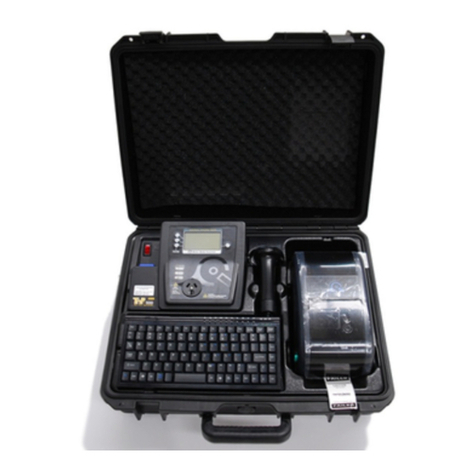
Wavecom TnP-500 User manual

Wavecom
User Manual
+ Certicate of Warranty and Product Support Information
TnP-500
Portable Appliance Test and Print Kit

Wavecom Certicate
of Warranty
The Manufacturer (Wavecom Instruments Pty. Ltd.) warrants its products against defects in materials and
workmanship for a period of 12 months from the date of purchase. During the warranty period, the Manufacturer
will repair (or at its option replace at no charge) the product that proves to be defective. This warranty does not
apply if the product has been damaged by accident, abuse, misuse or mis-application or as a result of service
or modification by anyone other than the Manufacturer of this tester.
The TnT & TnP Product Range of devices or its Manufacturer is not responsible for incidental or consequential
damages resulting from the breach of any express or implied warranty, including damage to property and to the
extent permitted by law, damages for personal injury. The distributors of this product cannot assume liability
or responsibility for any loss of damage resulting from the use of this device.
The Manufacturer reserves the right to discontinue models, change specifications, price or designs at any time
without notice or obligation.
Your Wavecom Appliance Tester comes with a
conditional 36 month warranty.
Your warranty applies unconditionally for 12 months from the date of purchase.
This can be extended an additional 12 months if your Tester is calibrated within 12
months of the date of purchase.
This can be extended a further 12 months if you calibrate you tester a second time
within 24 months of the date of purchase.

Product Support
Safety Information
Important Calibration Information
At Wavecom we take great pride in our customer service and support. We provide assistance,
troubleshooting and support over the phone, via Skype or Facetime, via email or in person to help
you get the most from your Wavecom Portable Appliance Tester. To be eligible for our support
services you must register your product.
You can register online at:
https://www.wavecom.com.au/wcm_product_registration.php
The TnP-500 has been designed to meet stringent safety requirements, however no device can
completely protect you from the consequences of incorrect use. The testing of electrical appliances
requires that extra care and caution is taken at all times to ensure personal safety.
The Manufacturer also advises that appliance testing should be conducted by a Competent Person
who is suitably trained (see Section 1.4.5 on Page 10 of AS/NZS 3760:2022 for the definition of
Competent Person), as well as any additional legislation or rulings in different states. If in doubt,
the manufacturer suggests the user contact their responsible authority.
For maximum safety, always ensure that the following advice is followed:
• The equipment being tested is in good condition and passes a visual check.
• All instructions are read, understood and followed.
• The power supply connections are always checked - if the N-E (middle) LED Indicator flashes
red, do not proceed before consulting the manual.
• Always use specified fuses and protection devices.
• Do not use leads that require repair or are damaged.
• If you are unsure, call a licensed Engineer/Electrician.
Your Wavecom Appliance Tester should be calibrated every 12 months. A correctly calibrated
tester is essential for ensuring testing accuracy is maintained, and for complying with the AS/NZS
3760:2022 standards.
To book your tester in for calibration, go to:
https://www.wavecom.com.au/calibrations
Then, send your tester to your nearest calibration service centre:
For Western Australian customers:
Wavecom WA Calibrations
Unit 2/17 Casino Street,
Welshpool, WA 6016
For all other customers:
Wavecom Calibrations
257 Grange Road,
Findon, SA 5023

4
TnP-500 User Manual Wavecom
Important Information 5
Contents 5
TnP-500 Diagrams 5
Precautions 6
WinPATS Premium 7
Operating the TnP-500 8
Powering on the Tester 8
Options Menu 8
Using your TnP-500 with WinPATS Premium PC Software 8
Using your TnP-500 with WinPATS Pro Android App 9
Using the TnP-500 Operating System 12
TnP-500 Testing Menu – Main Menu A 16
TnP-500 Testing Menu – Main Menu B 18
Meter Mode ® 23
Specications 24
Technical Information 25
Visual Inspection 25
Class 1 (Earthed Appliance) Construction 25
Class 2 (Double Insulated) Construction 26
Testing of Electrical Equipment 26
Leakage Test 27
Earth Continuity Test 27
3 Phase Testing 27
Integrated Tests 28
No Connection No Test 28
Wavecom Thermal Transfer Printer 29
Loading the media 30
Loading the printing ribbon 31
LED and Button Functions 32
Power on Utilities 32
Gap/Black Mark Sensor Calibration 33
Dump mode 33
Printer Initialization 34
Set Black Mark Sensor as Media Sensor and Calibrate the Black Mark Sensor 35
Set Gap Sensor as Media Sensor and Calibrate the Gap Sensor 35
Troubleshooting 35
Maintenance 37
Wavecom Tags & Ribbons 38
Other Information 39

5
TnP-500 User Manual Wavecom
Tester Serial & Purchase Information Rear Cover
Important Information
Contents
TnP-500 Diagrams
Case Diagram
• TnP-500 Integrated Appliance Tester
• Wavecom Thermal Transfer Printer
• Barcode Scanner
• Keyboard
• IEC Power Cable
• IEC Test Lead (500mm Orange)
• USB A to USB B Interface Cable
• Earth Lead with Alligator Clips (1800mm Black)
• Shockproof Industrial Case (IP67 Rated)
• 1 Roll (500) of White Labels
• 1 Roll of Printing Ribbon
• WinPATS Software License
• 12 Month Calibration Certificate
• 36 Month Conditional Warranty
• User Manual
On/Off Switch
Power Socket (Blue)
IEC Test Socket (Black) Head Unit
Keyboard
F1 Button
F2Button
F3 Button
LED Indicators
Storage Compartment
(Under Keyboard) Tag Printer
Barcode Scanner
LCD Screen
Enter Button
AS/NZS 3112 Appliance Test Socket

6
TnP-500 User Manual Wavecom
Head Unit Diagram
Storage Compartment Port Panel Diagram
Note: the Keyboard and Scanner ports are wired specifically to work with the included TnP-500 Keyboard and Barcode
Scanner, and will not operate as these ports (USB & RS-232) normally would.
Precautions
Competent Person
To ensure that all electrical equipment or devices are inspected, tested and tagged correctly, regulations
require that a ‘competent person’ such as a Licensed Electrician be employed to perform the required tests.
Please refer to the above definition as described in the current AS/NZS 3760:2022 Standard and in addition, to
any other local legislation or jurisdictions as may be relevant in your State.
A person competent to undertake Inspection and Testing of electrical equipment must have:
• Knowledge and practical experience of electricity and its hazards.
• A clear understanding of precautions to avoid danger.
• The ability to recognise at all times whether or not it is safe for work to continue.
• The ability to carry out visual examinations of electrical equipment.
• The ability to distinguish between electrical equipment that is double insulated and equipment that is
earthed as well as being able to identify the appropriate test for each type.
• The competency to safely carry out the Earthing Continuity, Insulation Resistance or Leakage Test and RCD
tests on electrical equipment.
• The knowledge of how to use the relevant testing instruments, interpret and record the results for
compliance with the Standard/Workplace requirements.
• The knowledge to be able to correctly recommend the frequency of testing required.
Due to the potential hazards of electrical testing, due care must be taken at all times.
Replacing Fuses
From time to time an appliance may cause an internal fuse within your TnP-500 to break. When this occurs you
will need to replace the fuse. If you prefer you can return your tester to Wavecom and we can replace the fuse
for you, or if you wish you may replace the fuse.
USB-B Port
for PC Data Transfer
Keyboard Port
Scanner Port

7
TnP-500 User Manual Wavecom
LED Indicators
Your TnP-500 checks the polarity and connectivity of the mains supply power and displays this information via
the LED Indicators. Each LED represents a comparison of the voltages between the Neutral to Earth, Active to
Earth, and Active to Neutral respectively.
If the A-E & A-N (green) lights are on and the N-E (red) light is off, the Mains Supply Test has
passed and you can continue with your testing.
If the central N-E light is on (red) there is a voltage difference between the Neutral and
Earth, or there is no Earth connected to the TnP-500 supply (this is likely to occur when
working with a generator or inverter).
DO NOT PROCEED if the N-E light is on and you intend to conduct load/leakage tests. If you
are carrying out standard Insulation and Earth Bond tests, it is generally safe to continue.
If both of the N-E (red) & A-E (green) lights are on, consult a qualified Electrician. This
indicates a fault with the Mains Supply. DO NOT PROCEED with any testing on this Mains
Supply.
WinPATS Premium
Your TnP-500 includes a license for WinPATS Premium, our asset management software designed specifically
for test and tagging. WinPATS™ software provides comprehensive fixed & portable asset management and is
able to track every aspect of an asset’s life from New to Service, to Safety Audits, to full item service history.
To install WinPATS Premium, download the software from our website:
https://www.wavecom.com.au/software
Once the download is complete, run WinPATS_Installer.exe.
When you are prompted to enter your 16 digit product key, use the code located on the WinPATS Premium flyer
that was included in your tester.
If your license does not validate, please contact us to obtain a new product key.

8
TnP-500 User Manual Wavecom
Operating your TnP-500
Powering on the Tester
Ensure all test cables (such as the Alligator Lead and Orange IEC lead) are removed, and that all your
peripherals (such as the keyboard, barcode scanner and printer) are connected.
Connect your TnP-500 to mains power via the supplied power lead, then turn the Power switch on.
Your TnP-500 will begin in Memory Mode, which allows you to store test results and item information in the
TnP-500’s memory, print tags, and use the other useful features of the TnP-500, in addition to the general
appliance testing functions.
To start your TnP-500 in Tester mode, which only allows you to conduct tests without saving results, press and
hold F3 while turning your TnP-500 on. Your TnP-500 will also start in Tester mode if no peripherals (such as the
keyboard, barcode scanner and printer) are connected.
The Barcode scanner will beep when your TnP-500 is powered on, indicating that it is also powered. If you do
not hear a beep from the scanner, check the scanner connection.
Initially the printer’s status light will be orange but after about 5-10 seconds it will change to green. The tester
will not print unless the printer light is solid green. A flashing red status light can indicate a media or general
printer fault (see ‘Wavecom Thermal Transfer Printer’ for more information).
Options Menu
During the course of using your TnP-500 you may need to adjust test parameters or other settings. To access
the Options Menu, hold Enter and press F2. We do not recommend adjusting the settings or test parameters
unless you are certain you understand the consequences of changing them.
In the Options Menu, use F2 to cycle through the various settings, press Enter to select a setting to adjust, and
use F1, F2, F3 and Enter to adjust the setting. To return to the Main Menu press F3.
Using your TnP-500 with WinPATS Premium PC Software
The TnP-500 can be operated directly from a PC using our WinPATS Premium PC Software, including running
tests, printing tags, creating reports and more. You can also upload your test results from the TnP-500 after a
period of testing if you prefer. Whichever method you choose, you will need to connect your TnP-500 to your
PC via the USB-A to USB-B cable provided. The USB-B port is located inside the storage compartment under the
keyboard of your TnP-500.
A full user manual for WinPATS Premium can be accessed from our website:
https://www.wavecom.com.au/onlinesupport/desktop/WinPATS_Help.html
We recommend reading the user manual, in particular the Getting Started section, before you begin testing, to
ensure you are comfortable with WinPATS Premium when you begin testing.

9
TnP-500 User Manual Wavecom
Using your TnP-500 with WinPATS Pro Android App
The WinPATS App can be used to control your tester, save your test results and generate reports. Detailed, step
by step guides for using WinPATS Pro are available on our website - www.wavecom.com.au
Before using your tablet with WinPATS, you must set it up as per the manufacturers instructions, and connect it
to the internet (via 4G or wifi). We also recommend that the tablet is fully charged before the first use.
Setup
Setting up the new WinPATS App is simple, but can take some time. We recommend setting up WinPATS before
you need to use it on site. You will need to download “WinPATS Pro” from the Google Play Store onto your
Android tablet. On our website, you can find a set of videos that will guide you through the various functions
and features of the new WinPATS App. This guide will walk through setting up WinPATS and connecting to your
tester.
Once you have downloaded the WinPATS App, open it and create up a 4 digit pin code. This will help keep your
data secure.
Next, it’s time to set up your Company Account. If your employer or organisation has an account already, you
can log in straight away using the details provided to you. Otherwise, tap Register Company to set up your
Company Account - you will be prompted to enable WinPATS’ permissions - this allows you to use the full set of
WinPATS features.
Now, fill in your details - a valid ABN is required to register a new company. You should use the address and
contact details of your head office. Once your details are entered, check they are correct, then tap Register.
You will be sent a One Time Password to the email you entered in the previous step. This is used to verify your
email address - enter the OTP to continue. This OTP is only valid for 10 minutes - if your OTP expires, simply go
back and then tap ‘Register’ again. If you don’t see your OTP email, check your spam folder.
Now you can pay for your WinPATS License. - you should have a coupon code on the rear of this booklet which
provides you with one free license for the WinPATS App. Your coupon code is linked to your tester, and you
will need to connect your Android tablet to your TnP-500 to authenticate your code. Using the USB-OTG cable
supplied with your tester, connect your tablet to your tester in the following chain:
Tablet > USB-OTG > USB-A to USB B Cable > USB B port of your TnP-500 (located inside the storage compartment
under the keyboard). See diagram below.
Then, enter your coupon code and tap APPLY. You should see the Total Amount number drop to zero. Tap PAY to
proceed.
WinPATS
USB-OTG Cable
USB-B to
USB-A Cable
Micro USB
USB-B USB-A

10
TnP-500 User Manual Wavecom
Once you have entered your code or paid, you can now Log In and set up your password. Enter the Company ID
and temporary Password which was emailed to you, which will enable you to log in for the first time. You will
now be prompted to set up a new password.
You can now set up your User Account - this is your individual profile. If you are the first or the only Test and
Tag technician at your organisation, you should set yourself as an ‘ADMIN’ user, which will allow you to use the
full features of WinPATS. Technician users have reduced access to features - this is designed for organisations
with multiple technicians and/or multiple sites.
Once your details are complete, tap ADD to create your account. Confirm your details are correct, then tap
CONFIRM to finish registering your user account.
When you start WinPATS for the first time you’ll be required to perform a data sync. This creates a new cloud
database for you, or connects your WinPATS App to your company’s existing database. If your database has
many items, this may take up to 5 minutes, but usually only takes a few seconds.
Connecting via Bluetooth
To control your TnP-500 via Bluetooth, you will need to perform a short setup procedure. Ensure you have both
your tablet with WinPATS installed, and your TnP-500 in front of you.
Go to the Bluetooth settings in your Tablet’s settings menu
Ensure that Bluetooth is enabled, then select your TnP-500 from the list of available devices (ensure you select
the correct tester by referring to the serial number. Your TnP-500’s serial number is located near the Power
Socket, and on the rear cover of this booklet).
You may now be prompted to pair your two devices using a PIN code. If so, your TnP-500 will display a code on
the screen. Enter this code into WinPATS and tap OK. You will be asked to confirm the connection - tap Confirm
after checking the details are correct.
Note: If you have any issues with the PIN code, you can disable this function from the TnP-500 settings menu. Power on
your TnP-500, then hold Enter and press F2 to open the settings menu. Navigate to ‘Bluetooth Configuration’ and press
Enter. When prompted with ‘Use Security PIN for Bluetooth’ select ‘Disable’ by pressing F3.
Go to the WinPATS App
To connect your TnP-500, go to the Test menu in the WinPATS App (at the top of the screen). You should be
prompted to connect a Wavecom Appliance Tester as soon as you open the Test Menu for the first time. Tap
‘BLUETOOTH’ to begin the Bluetooth setup process. WinPATS will scan for any available TnT or TnP testers and
display them in a list - select your tester from the list by tapping it. If you see multiple TnT or TnP products in
the list, use the serial number of your TnP-500 to identify your tester.
You will now be asked to register your TnP-500 - this allows you to receive product support, service and
calibration reminders from Wavecom. Once complete, tap Register. You’re now ready to start testing with
WinPATS!
11
TnP-500 User Manual Wavecom
Connecting via USB
You can also connect to your TnP-500 via USB if needed. Follow the following diagrams to connect your TnP-500
to your tablet or PC, with or without your printer. Please note that you need to connect your printer in addition
to your TnP-500 as shown.
Connecting your TnP-500 to your Tablet via USB
To connect your TnP-500 to your tablet via USB, you will need:
• A USB-A to USB-B cable (Included)
• A USB-OTG Cable (Included)
Connect your cables in the sequence shown below. Your TnP-500 USB-B port is located inside the storage
compartment under the keyboard. Once connected, open WinPATS on your tablet. You should see the Test icon
and the Print icon (if you connect the printer) at the top of the screen change to green.
Connecting your TnP-500 to your PC via USB
To connect your TnP-500 to your PC via USB, you will need:
• A USB-A to USB-B cable (Included)
Connect your cables in the sequence shown below. Your TnP-500 USB-B port is located inside the storage
compartment under the keyboard. You may need to update your USB Driver on your PC - you can download this
driver from our website: https://www.wavecom.com.au/support_download-software.php
WinPATS
USB-OTG Cable
USB-B to
USB-A Cable
Micro USB
USB-B USB-A
USB-B to
USB-A Cable
USB-B USB-A PC or Laptop
WinPATS

12
TnP-500 User Manual Wavecom
Using the TnP-500
The TnP-500 has a basic operating system that allows you to store User information, Sites and Items, as well as
access this information to retest Items, and export this data via our WinPATS Premium software.
Adding a Site
The TnT can hold up to 16 sites. To save items and test results, you will need at
least one Site added to the TnP-500’s memory.
From the initial screen, press F1.
Don’t hold the F1 key, this will select a different function.
The TnT can hold up to 16 sites. Press Enter to scroll through your sites. 3 Site ‘slots’
will be shown at a time. Each site corresponds to an “F” key, for example Site 1 = F1. To
add a new site or edit an existing site, hold the corresponding “F” key for 2 seconds.
If the Site has a *symbol next to the name then the site was uploaded from WinPATS and needs
to remain the same.
Using the keyboard, enter the name of the site. Once the details have been typed in
press Enter to return.
Once a site has been entered, the ‘F’ buttons are used to select the site. For example
to select site 1, F1 would be pressed.
Once a site has been selected, the TnT will return to the initial screen and the site that
was selected will be shown in the top left hand corner of the screen.
Adding a User
The TnT can hold up to 6 Users To save items and test results, you will need at
least one User added to the TnP-500’s memory.
From the initial screen, press F2 to access the Users menu.
Don’t hold the F2 key, this will select a different function.
Press Enter to scroll through the Users. 3 Users will be shown on each screen. Each
User corresponds to an “F” key, for example User 1 = F1. To add a new user or edit an
existing user, hold the corresponding “F” key for 2 seconds.
Using the keyboard, enter the name of the site. Once the details have been typed in
press Enter to return.
Once a user has been entered, the ‘F’ buttons are used to select the user. For example,
to select user 1, F1 would be pressed.

13
TnP-500 User Manual Wavecom
Adding an Item
Type in the new barcode or press F3 quickly to auto generate a barcode number. Once
a barcode has been specified, items can be entered. If the screen displays “search
barcode” press Enter to switch to new barcode. There must be no numbers entered in
to switch between the two modes.
A selection of details can be entered for an item. Details include; location, description,
make, model, serial number, asset number, frequency of test and notes. Each heading
relates to an ‘F’; e.g. Location = F1, Description = F2 and Make = F3. Only 3 items are
displayed at one time. To scroll through the various details, press Enter.
Please make sure that Location, Description, and Test Frequency are correctly entered.
Once the details are entered, hold Enter for 2 seconds to move on to the visual check
screen.
Entering an items details is the same process as entering sites and users, please refer
to the Adding a Site/User steps above. Ensure that test frequency for the item is set in
accordance with the AS/NZS 3760:2022 Standard.
After the item, has been visually inspected, there is 1 of 3 options that can be selected;
Out of Service (F2), Fail (F3) and Pass (Enter). If Out of Service or Fail is selected the
result will be saved and the TnT will revert back to the barcode entry screen. If you
have a zebra printer a tag will be printed.
If the test is a visual check only then hold Enter for two seconds - See below for details.
If the item passes a visual inspection and pass is selected, testing can begin. Select the
correct test based on the appliance type.
More detailed information regarding the testing process can be found from page 13.
Once test has been completed the results are displayed.
To test the item again, press (F3). This will take you back to the main menu A screen.
From here you can choose a test class. You would use this for example if testing power
boards. To complete the test, press enter. This will take you back to the new barcode
screen. If you have a zebra printer, a barcode will be printed once (enter) is pressed.

14
TnP-500 User Manual Wavecom
Barcode Generation
The TnT incorporates an auto generate barcode function which allows barcodes to be
generated sequentially after a barcode has been specified, for example: the specified
barcode is 1000 so the next barcode to be generated will be 1001, 1002, 1003 etc. This can be
accessed by holding F3 for 2 seconds on the Barcode Entry screen.
Once the auto generate menu has been accessed, the user can specify how many digits they
want in the barcode. The auto generate function allows a minimum of 2 and a maximum of 7
digits in the barcode to be generated. To increase the number of digits in the barcode, press
F1. To decrease the number of digits in the barcode, press F2. To proceed, press enter, or to
return to the Barcode Entry screen, press F3
If Enter was pressed, the user can now set the barcode that will begin the sequence. Key in a
barcode and press Enter to continue, or F3 to return the Barcode Entry screen.
If Enter was pressed, the user can specify whether or not to use leading zeros in the auto
generated barcode. For example: If the user selected 7 digits in the barcode and entered
1000 as the barcode, the barcode will be 0001000 if leading zeros are enabled. To enable
leading zeros, press F3. To disable, press enter. The current barcode that will be generated is
displayed in the bottom left hand corner of the Barcode Entry screen.
The current barcode that will be generated is displayed in the bottom left hand corner of
the Barcode Entry screen.
Visual Check Only
Items can be passed with a visual check only (no testing required). You must be at the
visual check screen shown on the left. To do a visual check only press and hold Enter for
2 seconds.
Pressing (enter) will take you back to the visual check screen. Pressing (F3) will complete
the test. Print out a tag if you have a zebra printer. Then go back to the new barcode screen.
Deleting Items
From the search barcode screen press and hold the Enter key. Then press the F1 key. The
feature cannot be selected when new barcode is displayed.
The search barcode will change to S/Record Del.
Scan or type the barcode that needs to be deleted. If the record does not exist or is in the
wrong site a message will be displayed saying nothing was found.
When a match is found a last warning message will be displayed. To delete the record hold
the F3 key for 2 seconds. To cancel press Enter.

15
TnP-500 User Manual Wavecom
Retesting Items
Type in or scan the barcode number to be searched and press enter. If the screen
displays new barcode press Enter to switch over. The screen can only be switched if
there is no entry.
The existing record details will be shown. Any changes made here will be updated once
the site is downloaded in WinPATS. If nothing needs changing, hold the Enter key to
proceed to the next screen.
After all item details have been entered, hold the Enter key for 2 seconds to proceed
to the Visual Check screen. After the item has been visually inspected, there is 1 of 3
options that can be selected; Out of Service (F2), Fail (F3) and Pass (enter). If Out of
Services or Fail is selected the result will be saved and the TnT will revert back to the
barcode entry screen, and a tag will be printed.
If the item passes a visual inspection and pass is selected, testing can begin.
Once test has completed the results are displayed.
To test the item multiple times press (F3) this will take you back to the main menu A
screen. From here you can choose a test class. You would use this for example if testing
power boards. To complete the test press (enter). This will take you back to the search
barcode screen. If you have a zebra printer a barcode will be printed once (enter) is
pressed.
Reprinting a Tag without Retesting
From the search barcode screen, enter barcode to search (From settings, advanced
search options can be enabled). Select the Select the record. Press and hold Enter till
screen with Loc | Desc | Make, press Enter, Model | SN | Asset, Press Enter one more
time to bring Freq | Notes | Tests
The search barcode will change to S/Record Del. Scan or type the barcode that needs
to be deleted. If the record does not exist or is in the wrong site a message will be
displayed saying nothing was found. Press F3
Press re-print the label.
Use Esc key to get back to previous menu when printing is done

16
TnP-500 User Manual Wavecom
TnP-500 Testing Menu – Main Menu A
Class 1 - Earthed Appliance Test - Menu A - F1
The Class 1 Test completes the following sequences as part of its procedure:
• Integrated Supply Mains Test - Refer to Integrated Test section
• Integrated NCNT Test - Refer to Integrated Test section
• Earth Bond Test (@ 200mA): 200mA test current, pass level less than 1Ω
• Insulation Test (@ 250V or 500V): pass level greater than 1MΩ
Note: 250V insulation testing applies to Class 1 appliances if selected (refer to Technical Information for details to change
test voltage).
In some situations, if the DUT is labelled with “Surge Protection Fitted” or if it contains MOV’s (Metal Oxide
Varistors), conduct a 250V-insulation test. If unsure refer to the AS/NZS 3760:2022 Standard. Should it still fail,
remove it from service. (Refer to the Technical Information section to change test voltage).
Note: Ensure that the device is isolated from any ground loop.
Procedure:
1. Complete a Visual Inspection (see page 22). If the device passed the Visual Inspection, continue with the
following instructions.
2. Plug device into appliance test socket.
3. Plug the IEC Clamp Cable into the IEC socket of the TnP-500
4. Connect earth clip to any exposed metal on the device. If this is not possible, you can use a metal mesh
braid to establish an earth connection (sold separately)
5. Navigate to Main Menu A, then Press the F1 key to begin the test
6. The test will be conducted
7. Once complete, read and record results appropriately
If the result was a PASS - Tag with PASS tag showing “next test due” date and return the device to service.
If the result was a FAIL - Tag the DUT with a DANGER tag and remove the device from service.

17
TnP-500 User Manual Wavecom
Class 2 Test - Double Insulation Test – Menu A - F2
The Double Insulation Test completes the following test sequences as part of its procedure:
1. Integrated Supply Mains Test - Refer to Integrated Test section
2. Integrated NCNT Test - Refer to Integrated Test section
3. Double Insulation Test (@250V or 500V): pass level greater than 1MΩ
Procedure:
1. Complete a Visual Inspection (see page 22). If the device passed the Visual Inspection, continue with the
following instructions.
2. Inspect the compliance plate to ensure the appliance is a Class 2 appliance.
Look for the double insulated symbol, seen here.
3. Plug the appliance into the appliance test socket of the TnP-500
4. Navigate to Main Menu A, then Press the F2 key to begin the test
5. Read and record results appropriately
If the result was a PASS - Tag with PASS tag showing “next test due” date and return the device to service.
If the result was a FAIL - Tag with a DANGER tag and remove the device from service.
Note: In some situations, if the device is labelled with “Surge Protection Fitted” or if it contains MOV’s (Metal Oxide
Varistors), conduct a 250V-insulation test. Always read the compliance plates before testing, especially on surge protected
powerboards. If unsure always refer to the AS/NZS 3760:2022 Standard. Should it still fail, remove it from service.
Lead Test (Extension Lead Test) – Menu A - F3
Note: Extension leads should always be uncoiled before using or testing. Please ensure that the IEC Adaptor & the IEC
socket are inserted firmly or it may result in a continuity/polarity fail.
The Lead Test completes the following sequence as part of its comprehensive testing procedure:
1. Integrated Supply Mains Test - Refer to Integrated Test section
2. Earth Bond Test (@ 200mA): 200mA test current, pass level less than 1Ω
3. Insulation Test (@ 250V or 500V): pass level greater than 1MΩ
4. Continuity and Polarity Test 240VAC @ 2mA Checks continuity & polarity of leads
Procedure:
1. Complete a Visual Inspection (see page 22). If the device passed the Visual Inspection, continue with the
following instructions.
2. Plug in the IEC-550 Orange Lead adaptor lead supplied into the IEC socket.
3. Plug male end of extension lead or power board into the appliance test socket.
4. Connect the IEC-550 Orange lead to your extension lead
5. Navigate to Main Menu A, then Press the F3 key to begin the test
6. Read and record results appropriately.
If the result was a PASS - Tag with PASS tag showing “next test due” date and return the device to service.
If the result was a FAIL - Tag with a DANGER tag and remove the device from service.

18
TnP-500 User Manual Wavecom
TnP-500 Testing Menu – Main Menu B
Use the Enter button to switch between Menu A and Menu B. All tests on Menu B require a Mains Power source.
Power Test - Menu B – F1
The Power Test is for the purposes of monitoring and performance of equipment. The Power Test feature is
for single phase appliances only. The Power Test allows the user to turn the appliance on and measure its
performance as a digital wattmeter.
Displayed parameters are:
• Volts AC
• Current
• Volt Amp
• Power Factor
• Watts
This test is ideal for service agents and electricians. The user can plug in the appliance and turn it on with real
time measurements displayed on the display. This is useful when testing an appliance with a compliance/
name plate on it. The operator can compare the name plate details of operating voltage, operating current,
and power factor etc. Should the appliance exceed the said values on the name plate it could be deemed faulty
and require service.
The Power Test completes the following sequence as part of its comprehensive testing procedure:
1. Integrated Supply Mains Test - Refer to Integrated Test section
2. Power Test
Caution: Before operating ensure the equipment is firmly secured to eliminate the possibility of causing injury
or damage. This function will power the appliance on, and in the case of appliance with movable parts these
parts may begin to move. Ensure the appliance can power on safely before proceeding.
Procedure:
1. Complete a Visual Inspection (see page 22). If the device passed the Visual Inspection, continue with the
following instructions.
2. Ensure the appliance is safely located and secured, as it will be powered and operational during this test.
3. Plug male end of appliance into Appliance Test Socket.
4. Press F1 to start the power test.
5. A warning message will appear on screen. If the appliance is safely located and secured press F3 to
proceed. The unit will power on.
6. Read and record results appropriately.
7. Once the appliance has powered down and the test is complete, unplug the unit.
8. Press Enter to return to the main menu.
Note: Because the power test is not required in the electrical testing standards there is no pass/fail value built in to the
tester. It is up to the user to determine if the item is a pass or a fail based on the compliance/name plate.
If the result was a PASS - Tag with the appropriate tag including “next test due” date and “return to service”.
If the result was a FAIL - Tag with a DANGER TAG and remove the unit from service.

19
TnP-500 User Manual Wavecom
Leakage / Run Test – Menu B – F2
The Leakage Test is an alternate method to perform insulation resistance tests. Leakage testing is a major
function of the TnP-500. There are three types of Leakage test available on the TnP-500 - take care to ensure
you use the correct test for your appliance.
This test determines errors of leakage not otherwise detected in a normal insulation test. If there are any
doubts with insulation testing of the equipment, the Standard (AS/NZS 3760:2022) allows for a leakage test to
be carried out instead. The TnP-500 has been designed to perform these tests. The Leakage Test applies power
to the Device Under Test (DUT) and measures any imbalance or leakage current. The leakage is tested to the
limits of the class types specified in the Standard AS/NZS 3760:2022 i.e. Class 1 = > 5mA as Fail.
The limit of imbalance measured on the TnP-500 will read well in excess of the limits set in mA. However,
should the supply circuit be protected by an RCD this device will trip anywhere between 10 to 30mA and trip
the mains supply switch OFF. The Leakage Test allows the user to operate the appliance in normal operation
conditions and measure its Operating Leakage current. The displayed parameter is mA. The mA Display Range
0.0 to 22.0 mA.
A predefined value for individual class types is programmed into your TnP-500. These limits are set according
to the AS/NZS 3760:2022 Standards. Should these values change in future it can be simply altered in firmware.
The run time period can be adjusted (by 5 second increments). The value can be changed by selecting the
leakage test time in the options menu. See the special functions section of the manual for more details. The
factory default setting is 20sec. The value for the leakage runtime is also used for the power test.
Caution: Before operating ensure the equipment is firmly secured to eliminate the possibility of causing injury
or damage. This function will power the appliance on, and in the case of appliance with movable parts these
parts may begin to move. Ensure the appliance can power on safely before proceeding.
Procedure:
1. Complete a Visual Inspection (see page 22). If the device passed the Visual Inspection, continue with the
following instructions.
2. Ensure that the appliance is safely located and secure as it will be powered & operational during this test.
3. Plug the appliance into the Appliance Test Socket of the TnP-500
4. If testing a Class 1 Appliance, plug the IEC Clamp Cable into the IEC socket of the TnP-500, then clamp it
onto earthed metal on the appliance
5. If testing an RCD, plug the IEC-550 Orange Cable into the IEC socket of the TnP-500, then plug it into a
socket on your RCD and turn that switch on
6. Navigate to Main Menu B, then press F2 to enter the Leakage Test Menu
7. Press a function key to start the test
F1 = Earth Leakage, limit set to MAX then 5mA fail
F2 = Double Insulated Leakage and Extension Leads, limit set to MAX then 5mA fail
F3 = RCD Leakage (not a full RCD Trip Time or Ramp Test)
8. The TnP-500 will conduct the first part of the test without powering the appliance
9. A warning will be displayed on screen - ensure the appliance is safely located, then press F3 to power the
appliance and continue the leakage test
10. Your results will appear on the screen - you can now print the tag and unplug the appliance
If the result was a PASS - Tag with the appropriate tag including “next test due” date and “return to service”
If the result was a FAIL - Tag with a DANGER TAG and remove from service.

20
TnP-500 User Manual Wavecom
RCD Tests – Time Test / Ramp Test– Menu B – F3
Before Testing
When any RCD testing is to be carried out on any circuit that is protected by an RCD in the main switchboard
(upstream), it’s most likely to trip this upstream RCD. When performing RCD Trip Time or Ramp current tests on
any portable RCD devices, the RCD in the switchboard may trip faster. This is due to increased upstream levels
of leakage current from the additional circuits and devices connected to it. The fixed RCD’s may also have
better connectivity, sensitivity and mechanical mechanisms.
To avoid tripping large areas in the work place monitored by the switchboard RCD it is suggested that an
Isolation Transformer be used. Wavecom offer an Isolation Transformer, designed specifically for the purposes
of field RCD tripping. Do not use these transformers for any other purpose. Rated 240VAC In, 240VAC Out @
30VA. Fuse protected, Primary Winding 500mA.
Types of RCD
There are two types of RCD - Type 1 and Type 2:
Type 1 - Has a trip time of < 40mS and a trip current of < 10mA. These types of RCD’s are mainly used on sites
containing medical equipment. These types of RCD’s must be compliant with the AS3551 standard. (Please refer
to AS3551 for specific guidance)
Type 2- Has a trip time of < 300mS and a trip current of < 30mA. This is the default setting on all new units.
Unless specified on the RCD device, nearly all RCD will be this type, however as with all electrical testing, take
care to confirm the RCD type before testing.
RCD Testing Setup
When testing RCDs, different kinds of RCDs will require different test setups. Consult the diagrams below to
determine which setup is required for your situation. Note the presence of the Isolation Transformer between
the Portable RCDs and the GPO. This ensures any switchboard RCDs are not tripped when testing Portable
RCDs.
Testing Fixed RCDs
Connect Blue Power Cable from
TnP-500 IEC Power Socket directly to
GPO.
Testing Portable RCDs with
no physical switch
Connect in series:
Blue Power Cable from TnP-500 IEC Power
Socket to RCD, to Isolation Transformer,
to GPO
Testing Portable RCDs
with physical switches
Connect in series:
Blue Power Cable from TnP-500 IEC Power
Socket to RCD, to Isolation Transformer, to
GPO.
Ensure the RCD socket is switched on.
Repeat for each outlet on RCD.
Table of contents
Other Wavecom Test Equipment manuals

Wavecom
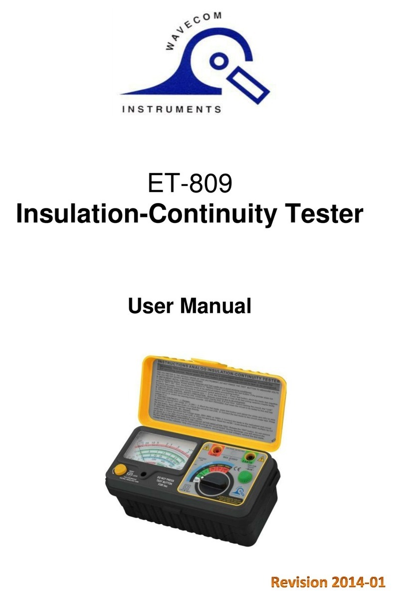
Wavecom ET-809 User manual

Wavecom
Wavecom TnP 3PLM 20A User manual

Wavecom
Wavecom TnT Titan 20A User manual

Wavecom
Wavecom WCM-RCD User manual

Wavecom
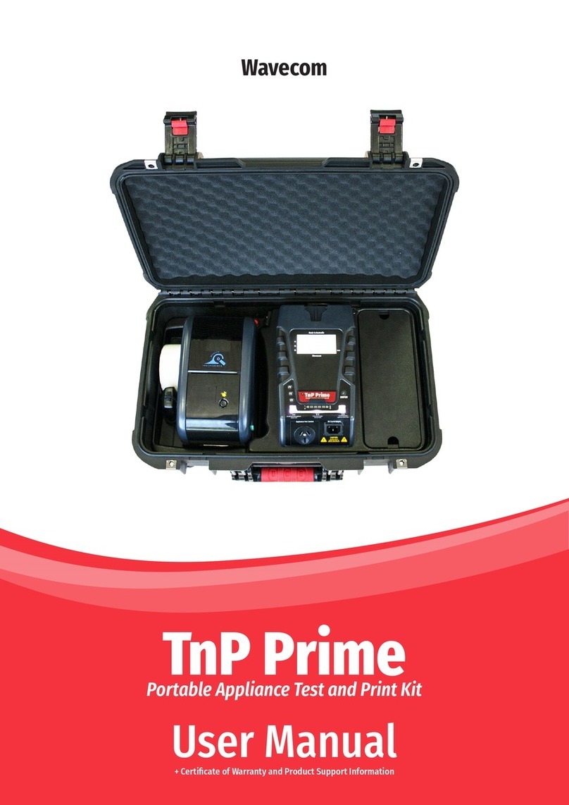
Wavecom TnP Prime User manual

Wavecom
Wavecom TnT RCD User manual

Wavecom
Wavecom TnP-500X User manual

Wavecom
Wavecom TnP Prime User manual

Wavecom
Wavecom TnT Titan User manual