Zehnder Rittling ComfoLED Quick start guide

ComfoAir 70 / ComfoSpot 50
ComfoLED / ComfoLED CH
Montagehinweise - Installation notes - Instructions de montage - Indicazioni per
il montaggio - Montageaanwijzingen - Wskazówki dotyczące montażu
Decorative radiators Comfortable indoor ventilation Heating and cooling ceiling systems Clean air solutions
ComfoLED
ComfoLED CH

2
Alle Rechte vorbehalten.
Die Zusammenstellung dieser Bedienungsanleitung erfolgte mit größter Sorgfalt. Dennoch
haftet der Herausgeber nicht für Schäden aufgrund von fehlenden oder nicht korrekten An-
gaben in dieser Bedienungsanleitung. Bei Meinungsverschiedenheiten ist der deutsche Ori-
ginaltext letztendlich verbindlich.
All rights reserved.
This manual has been compiled with the utmost care. However, the publisher cannot be held
liable for any damage caused as a result of missing or incorrect information in this manual. In
case of disputes the German version of these instructions will be binding.
Tous droits reserves.
Ce manuel a ete compose avec le plus grand soin. L‘editeur ne peut neanmoins pas etre te-
nu responsable de dommages decoulant d‘informations manquantes ou erronees dans ce
manuel. En cas de diérend, seule la version allemand de ce mode d’emploi est contraig-
nante.
Tutti i diritti riservati.
La presente documentazione e stata redatta con la massima attenzione. L‘editore non
puo comunque essere ritenuto responsabile di eventuali danni derivanti dalla mancan-
za o dall‘inesattezza delle informazioni qui fornite. In caso di disaccordo, fa fede l‘originale
in lingua tedesca.
Alle rechten voorbehouden.
Bij de samenstelling van deze handleiding is uiterste zorg betracht, de uitgever kan ech-
ter niet verantwoordelijk worden gehouden voor enige schade ontstaan door het ontbreken
of onjuist vermelden van informatie in deze handleiding. In geval van onenigheid is de Du-
its tekst leidend.
Wszelkie prawa zastrzeżone.
Niniejsza instrukcja obsługi została sporządzona z najwyższą starannością. Wydawca nie
ponosi odpowiedzialności za jakiekolwiek szkody powstałe na skutek nieumieszczenia w niej
informacji lub umieszczenia w niej nieprawidłowych informacji. W przypadku sporów wiążąca
jest wersja niniejszej instrukcji w języku niemiecki.

3
Montageanleitung .............................................................................
Installation notes ...............................................................................
Instructions de montage ..................................................................
Indicazioni per il montaggio ...............................................................
Montageaanwijzingen .......................................................................
Wskazówki dotyczące montażu ........................................................
4-7
8-11
12-15
16-19
20-23
24-27

4
externe Bedieneinheit
Verwendungszweck
Die Comfo LED (ComfoLED CH)
bietet die Möglichkeit das Lüftungs-
gerät bequem aus der Ferne zu
bedienen. Das Bedienteil ist aus-
schließlich für eine Unterputzin-
stallation im Innenbereich in die
marktüblichen Schalterprogramme
geeignet und wird über ein maxi-
mal 25 m langes, 4-adriges Kabel
(z.B. Typ: J-Y(ST)Y 2x2x0,6) mit
dem Lüftungsgerät verbunden.
Aufbau / Lieferumfang
Pos Bezeich-
nung
Lieferumfang
Bemerkung
ComfoLED ComfoLED CH
1Funktions-
einheit x x
bestehend aus: berührungssensi-
tive Schaltäche, Anschlussplatine
mit Federzugklemmen und Halte-
platte mit Rastfüßen
2Blend-
rahmen x
Blendrahmen des Schalterpro-
gramms muss über ein Standard-
maß von 55x55 mm zur Aufnahme
der Funktionseinheit verfügen
3UP-
Rahmen x x
4
4-poliges
Anschluss-
kabel
x x
mit verpresster Buchse der Mik-
rosteckverbindung und Steckver-
binder an den Kabelenden (ohne
Abbildung)
ComfoLED
ComfoLED CH
32
1
32
1

5
Funktionalität
Die Bedieneinheit verfügt über be-
rührungssensitive Schaltächen,
das heißt, durch Berühren der be-
treenden Tasten werden die je-
weiligen Bedienfunktionen aus-
gelöst. Das Lüftungsgerät kann
gleichzeitig mit der internen und
der externen Bedieneinheit betrie-
ben werden. Dabei sind die Tasten-
belegungen und die LED-Signali-
sierungen beider Bedienteile funk-
tional gleich.
Installation
Vor Eingri in das Lüftungs-
gerät ist die Netzzuleitung
allpolig von der Spannungsversor-
gung zu trennen.
Bei Nichtvorhandensein eines RF-
Moduls muss der elektrische An-
schluss im ausgebauten Zustand
des Lüftungsgerätes durchgeführt
werden. Beachten Sie dazu die
Montageanweisungen in den ein-
schlägigen Betriebsanleitungen.
Zum Schutz vor elektrostatischen
Einwirkungen ist ein ESD-Armband
anzulegen.
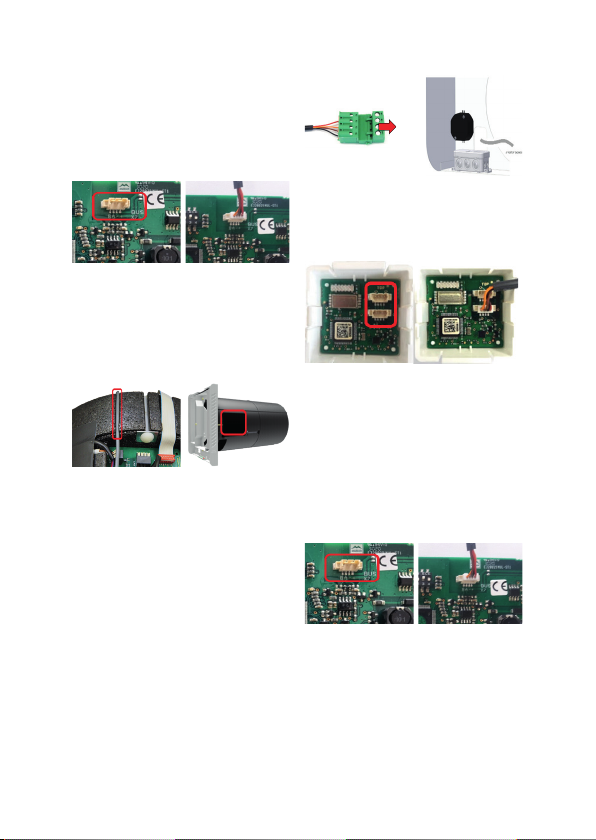
Elektrischer Anschluss
Lüftungsgeräteseitig:
Die Buchse der Mikrosteckverbin-
dung des Anschlusskabels ist in
den Stecker der Mikrosteckverbin-
dung BUS X7 der Steuerungspla-
tine des Lüftungsgerätes einzuste-
cken.
Bei ggfs. vorhandenem RF-Mo-
dul ist die Buchse der Mikrosteck-
verbindung des Anschlusskabels
in eine der auf der Platine des RF-
Moduls doppelt ausgeführten Mik-
rosteckverbindung einzustecken.
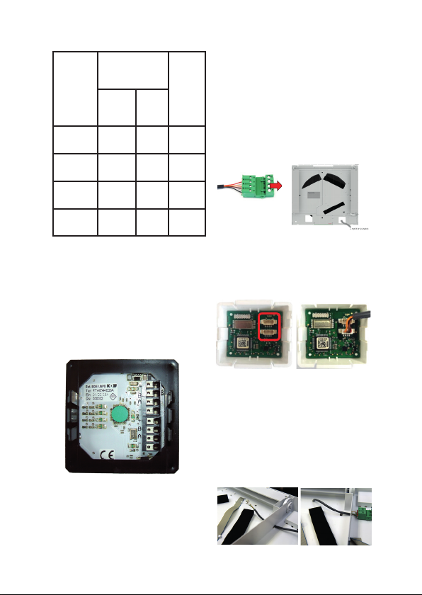
Das Bindeglied zwischen An-
schlusskabel und dem bauseitigen
Kabel zur externen Bedieneinheit
ist der 2-teilige Steckverbinder mit
Federzug- und Schraubklemmen.
Die Adern des Kabels zur externen
Bedieneinheit sind beim Lüftungsge-
rät am Teil der Steckverbindung mit
den Schraubklemmen anzuklem-
men.
Achten Sie auf übereinstimmende
Aderbelegung bezüglich der Feder-
zugklemmen des Steckverbinders
und den Federzugklemmen der An-
schlussplatine Bedieneinheit.
externe Bedieneinheit

6
Farb-
codie-
rung
An-
schluss-
kabel
Aderbelegung
Federzugklem-
men
Farb-
codie-
rung
Kabel
bau-
seits
Steck-
verbin-
der
Be-
dien-
einheit
Rot (RT) + +
Orange
(OR)
B B
Braun
(BR)
A A
Schwarz
(SW)
- -
Bedienteilseitig:
Die Adern des Kabels sind entspre-
chend der Farbcodierung an die Fe-
derzugklemmen +, B, A, - der An-
schlussplatine der Bedieneinheit an-
zuschließen. Dabei das Kabel zuerst
durch den Blendrahmen führen!
Drücken Sie die Funktionseinheit
vorsichtig und lagerichtig mit je-
weils seitlicher Position der Rast-
füße in den UP-Rahmen bis der
Blendrahmen xiert ist.
ComfoSpot 50
Ziehen Sie das Steckverbindungs-
teil mit den Schraubklemmen ab und
klemmen Sie die Adern des bausei-
tigen Kabels an. Notieren Sie die
Farbcodierung!
Im Falle eines eingebauten RF-
Moduls stecken Sie die Buchse in
einen der noch freien Stecker der
zweifachen Mikrosteckverbindung.
Ansonsten ist der Netzanschluss
abzuklemmen und das Gerät bis
zum freien Zugri auf die Steue-
rungsplatine aus dem Wandein-
baurohr herauszuziehen.
Führen Sie das mit der Buchse en-
dende Anschlusskabel durch die
Önungen der Unterschale.
externe Bedieneinheit

7
Stecken Sie nach Abnahme der
PVC-Abdeckung der Steuerungs-
platine die Buchse vorsichtig in den
Stecker der Mikrosteckverbindung
BUS X7 der Steuerungsplatine.
Verlegen Sie das Anschlusskabel
in der vorgesehenen Kabelmulde
des EPP-Gehäuses und verschlie-
ßen Sie die Steuerungsplatine mit
der PVC-Abdeckung.
Klemmen Sie nach Einschieben des
Gerätes in das Wandeinbaurohr das
Netzanschlusskabel an. Stecken
Sie die beiden Teile des Steckver-
binders zusammen und verbringen
Sie die Steckverbindung im Bereich
der Kabeleinführung.
ComfoAir 70
Ziehen Sie das Steckverbindungs-
teil mit den Schraubklemmen ab
und klemmen Sie die Adern des
bauseitigen Kabels an.Notieren Sie
die Farbcodierung!
Im Falle eines eingebauten RF-Mo-
duls stecken Sie die Buchse in ei-
nen der noch freien Stecker der
zweifachen Mikrosteckverbindung.
Ansonsten ist das Gerät bis zum
freien Zugri auf die Steuerungs-
platine ca. 15 cm aus dem Wand-
einbaurohr herauszuziehen.
Stecken Sie die Buchse vorsichtig
in den Stecker der Mikrosteckver-
bindungg BUS X7 der Steuerungs-
platine.
Stecken Sie nach Einschieben des
Gerätes in das Wandeinbaurohr die
beiden Teile des Steckverbinders
zusammen und verbringen Sie die
Steckverbindung im freien Bereich
vor der Steuerungsplatine.
externe Bedieneinheit

8
External control panel
Intended purpose
The Comfo LED (ComfoLED CH)
allows the ventilation unit to be
conveniently operated remote-
ly. The control panel is only suit-
able for indoor in-wall installation
in conventional switch ranges and
is connected to the ventila-
tion unit with a 4-core cable with
a maximum length of 25 m
(e.g. type: J-Y(ST)Y 2x2x0.6).
Design / Scope of delivery
Functionality
Item Descrip-
tion
Scope of delivery
Note
ComfoLED ComfoLED CH
1Function
unit x x
Consisting of: touch-sensitive but-
ton, connection board with spring-
type terminals and retaining plate
with snap-in feet
2Cover
frame x
The cover frame of the switch
range must have stand-
ard dimensions of 55x55 mm
in order to hold the function unit
3In-wall
frame x x
4
4-pin con-
nection
cable
x x
With press tted socket of the mi-
cro connection and plug-in connec-
tor at the cable ends (not illustrated)
ComfoLED
ComfoLED CH
32
1
32
1

9
Functionality
The control panel has touch-sensi-
tive buttons, which means the re-
spective operating functions are
triggered by touching the relevant
buttons. The ventilation unit can
be operated at the same time with
the internal and the external con-
trol panel. The button assignments
and the LED signalling in both con-
trol panels are identical in terms of
functions.
Installation
Before reaching into the
ventilation unit, disconnect
all poles of the mains supply line
from the power supply.
If an RF module is not present, the
electrical connection must be car-
ried out with the ventilation unit dis-
assembled. Observe the installa-
tion instructions in the relevant us-
er manuals.
To provide protection against elec-
trostatic eects, an ESD armband
is to be applied.
Electrical connection
Ventilation unit side:
The socket of the connection ca-
ble’s micro connection must be in-
serted into the plug of the BUS X7
micro connection on the ventilation
unit’s control board.
If an RF module is present, the
socket of the connection cable’s
micro connection must be inserted
into one of the dual micro connec-
tions on the RF module board.
The 2-part plug-in connector with
spring-type and screw-type ter-
minals is the connecting link be-
tween the connection cable and the
on-site cable for the external con-
trol unit.
The wires of the cable for the exter-
nal control unit are to be connected
to the part of the plug connection
with the screw-type terminals on
the ventilation unit.
Ensure that the wire assignment
matches the spring-type terminals
of the plug-in connector and the
spring-type terminals of the control
unit’s connection board.
External control panel

10
Colour
coding of
the con-
nection
cable
Wire assign-
ment spring-
type terminals
Colour
coding
of the
on-site
cable
Plug-in
connec-
tor
Con-
trol
unit
Red
(RD)
+ +
Orange
(OG)
B B
Brown
(BN)
A A
Black
(BK)
- -
Control panel side:
The cable wires are to be connect-
ed to the +, B, A, - spring-type ter-
minals on the control panel con-
nection board according to the
colour coding. Guide the cable
through the cover frame rst.
Carefully push the correctly posi-
tioned function unit with the snap-
in feet in the lateral position into the
in-wall frame until the cover frame
is xed in place.
ComfoSpot 50
Disconnect the plug-in connector
part with the screw-type terminals
and connect the wires of the on-
site cable. Make a note of the col-
our coding.
In case of a built-in RF module, in-
sert the socket into one of the plugs
of the dual micro connection that is
still available.
Otherwise, disconnect the mains
power supply and pull the unit out
of the wall mounting pipe until the
control board is freely accessible.
Guide the connection cable ending
with the socket through the open-
ings in the bottom cover.
External control panel

11
After removing the PVC cover of
the control board, carefully insert
the socket into the plug of the con-
trol board’s BUS X7 micro connec-
tion.
Install the connecting cable in the
designated cable recess of the
EPP housing and close the control
board with the PVC cover.
After sliding the unit into the wall
mounting pipe, connect the mains
power supply. Plug both parts of
the plug-in connector together and
pass the plug connection into the
cable entry area.
ComfoAir 70
Disconnect the plug-in connector
part with the screw-type terminals
and connect the wires of the on-
site cable. Make a note of the col-
our coding.
In case of a built-in RF module, in-
sert the socket into one of the plugs
of the dual micro connection that is
still available.
Otherwise, pull the device out of
the wall mounting pipe by approx.
15 cm until the control board is
freely accessible.
Carefully insert the socket into the
plug of the control board’s BUS X7
micro connection.
After sliding the unit into the wall
mounting pipe, plug the two parts
of the plug-in connector together
and pass the plug-in connector in-
to the free area in front of the con-
trol board.
External control panel

12
Interface de commande externe
Utilisation prévue
Le Comfo LED (ComfoLED CH)
permet une commande aisée de
l’appareil de ventilation à distance.
L’interface de commande est exclu-
sivement conçue pour une installa-
tion encastrée en intérieur, dans les
gammes d’interrupteurs courantes
sur le marché. Elle est raccordée
à l’appareil de ventilation au moyen
d’un câble à 4 conducteurs de 25 m
de long maximum (p. ex. du type :
J-Y(ST)Y 2 x 2 x 0,6).
Structure / contenu de la
livraison
Pos. Désignation
Contenu de la livraison
Remarque
ComfoLED ComfoLED CH
1Unité fonc-
tionnelle x x
Comprend : surface tactile, platine
de raccordement avec bornes à
ressort et plaque de retenue avec
pattes d’emboîtement
2Cache x
Le cache de la gamme d’interrup-
teurs doit avoir des dimensions
standard de 55 x 55 mm pour pou-
voir accueillir l’unité fonctionnelle
3Cadre en-
castré x x
4
Câble de rac-
cordement à
4 pôles
x x
Avec connecteur femelle serti du
microconnecteur et connecteur sur
les extrémités du câble (non repré-
senté)
ComfoLED
ComfoLED CH
32
1
32
1

13
Fonctionnalité
L’interface de commande dispose de
surfaces tactiles, si bien qu’il sut
d’eeurer les touches correspon-
dantes pour activer les fonctions
associées. L’appareil de ventilation
peut être commandé simultané-
ment par l’interface de commande
interne et l’interface de commande
externe. Pour ce faire, l’aectation
des touches et les signaux LED sont
identiques sur le plan fonctionnel sur
les deux interfaces de commande.
Installation
Avant d’intervenir sur l’ap-
pareil de ventilation, débran-
cher de l’alimentation électrique tous
les pôles du câble d’alimentation
secteur.
Si un module RF n’est pas présent,
le raccordement électrique doit être
eectué lorsque l’appareil de ven-
tilation est démonté. Pour ce faire,
respecter les instructions de mon-
tage gurant dans les modes d’em-
ploi correspondants. Porter un bra-
celet antistatique pour prévenir les
décharges électrostatiques.
Raccordement électrique
Côté appareil de ventilation :
Le connecteur femelle du micro-
connecteur du câble de raccorde-
ment doit être branché sur le connec-
teur du microconnecteur BUS X7 de
la platine de commande de l’appa-
reil de ventilation. Si un module RF est
présent, le connecteur femelle du mi-
croconnecteur du câble de raccorde-
ment doit être branché sur l’un des mi-
croconnecteurs doubles de la platine du
module RF. Le connecteur en 2 parties
avec bornes à ressort et à vis sert d’élé-
ment de liaison entre le câble de rac-
cordement et le câble fourni par le client
vers l’interface de commande externe.
Les conducteurs du câble menant
à l’interface de commande externe
doivent être branchés au niveau de
l’appareil de ventilation à la partie du
connecteur avec les bornes à vis.
S’assurer que l’aectation des
conducteurs correspond aux bornes
à ressort du connecteur et aux
bornes à ressort de la platine de rac-
cordement de l’interface de com-
mande.
Interface de commande externe

14
Code
couleur
câble de
raccor-
dement
Aectation des
conducteurs
Code
couleur
câble
fourni
par le
client
Con-
necteur
Inter-
face
de
com-
mande
Rouge + +
Orange B B
Brun A A
Noir - -
Côté interface de commande :
Les conducteurs du câble doivent
être branchés conformément au
code couleur aux bornes à ressort +,
B, A, - de la platine de raccordement
de l’interface de commande. Le
câble doit tout d’abord être passé à
travers le cache !
Enfoncer avec précaution l’unité
fonctionnelle correctement position-
née avec les pattes d’emboîtement
sur les côtés dans le cadre encas-
tré, jusqu’à ce que le cache soit xé.
ComfoSpot 50
Retirer la partie du connecteur
avec les bornes à vis et brancher
les conducteurs du câble fourni par
le client. Attention au code couleur !
Dans le cas d’un module RF inté-
gré, brancher le connecteur femelle
sur l’un des connecteurs encore
libres du microconnecteur double.
Dans le cas contraire, débrancher
le raccordement au secteur et sor-
tir l’appareil du tube de montage
mural jusqu’à ce que la platine de
commande soit librement acces-
sible.
Faire passer le câble de raccorde-
ment se terminant par le connec-
teur femelle à travers les ouver-
tures de la coie inférieure.
Interface de commande externe

15
Après avoir retiré le couvercle en
PVC de la platine de commande,
brancher avec précaution le
connecteur femelle sur le connec-
teur mâle du microconnecteur BUS
X7 de la platine de commande.
Acheminer le câble de raccordement
dans la rainure de câble prévue à cet
eet du boîtier en EPP et fermer la
platine de commande avec le cou-
vercle en PVC.
Après avoir inséré l’appareil dans le
tube de montage mural, brancher le
câble de raccordement secteur. Em-
boîter les deux parties du connec-
teur et amener le connecteur dans la
zone du passe-câble.
ComfoAir 70
Retirer la partie du connecteur
avec les bornes à vis et brancher
les conducteurs du câble fourni par
le client. Attention au code couleur !
Dans le cas d’un module RF inté-
gré, brancher le connecteur femelle
sur l’un des connecteurs encore
libres du microconnecteur double.
Dans le cas contraire, l’appareil
doit être retiré du tube de montage
mural d’env. 15 cm jusqu’à ce que
la platine de commande soit libre-
ment accessible.
Brancher avec précaution le
connecteur femelle sur le connec-
teur du microconnecteur BUS X7
de la platine de commande.
Après avoir inséré l’appareil dans
le tube de montage mural, emboî-
ter les deux parties du connecteur
et amener le connecteur dans l’es-
pace libre devant la platine de com-
mande.
Interface de commande externe

16
Unità di comando esterna
Impiego previsto
Comfo LED (ComfoLED CH) ester-
na ore la possibilità di controllare
comodamente a distanza il dispo-
sitivo di ventilazione. Il pannello di
comando è idoneo esclusivamen-
te all’installazione incassata all’in-
terno di gamme di interruttori comu-
ni e viene collegato al dispositivo di
ventilazione per mezzo di un cavo a
4 li di massimo 25 m di lunghezza
(ad es. del tipo J-Y(ST)Y 2x2x0,6).
Struttura / dotazione
Pos. Denomi-
nazione
Dotazione
Osservazione
ComfoLED ComfoLED CH
1
Unità
funzio-
nale
x x
Costituta da: supercie di contatto
sensibile al tatto, scheda elettronica
con morsetti a molla e piastra di sup-
porto con piedini a scatto
2 Cornice x
Per poter accogliere l’unità funziona-
le, la cornice della gamma di interrut-
tori deve avere una misura standard
di 55x55 mm
3Telaio ad
incasso x x
4
Cavo di
collega-
mento a
4 poli
x x
con presa crimpata del microconnet-
tore e connettore a spina alle estremi-
tà del cavo (non illustrato)
ComfoLED
ComfoLED CH
32
1
32
1

17
Funzionalità
L’unità di comando presenta super-
ci di contatto sensibili al tatto, vale
a dire che toccando determinati pul-
santi si attivano le rispettive funzioni
di comando. Il dispositivo di ventila-
zione può essere utilizzato contem-
poraneamente con l’unità di coman-
do interna e con quella esterna. Dal
punto di vista delle funzioni, le asse-
gnazioni dei pulsanti e le segnalazio-
ni dei LED dei due pannelli di coman-
do sono identiche.
Installazione
Prima di intervenire sul di-
spositivo di ventilazione,
scollegare tutti i poli della linea di ali-
mentazione dalla rete elettrica.
Se non è presente un modulo RF, il
collegamento elettrico deve essere
eettuato con il dispositivo di venti-
lazione smontato. Osservare le istru-
zioni di installazione nelle relative
istruzioni per l’uso. A protezione da-
gli eetti delle scariche elettrostati-
che, va indossato un bracciale ESD.
Collegamento elettrico
Lato del dispositivo di ventilazione:
La presa del microconnettore del ca-
vo di collegamento deve essere in-
serita nella spina del microconnetto-
re BUS X7 della scheda di comando
del dispositivo di ventilazione.
Se è presente un modulo RF, la
presa del microconnettore del cavo
di collegamento deve essere inseri-
ta in uno dei microconnettori doppi
sulla scheda del modulo RF.
L’elemento di unione tra il cavo di
collegamento e il cavo predisposto
dal cliente verso l’unità di coman-
do esterna è il connettore a spina
a 2 elementi con morsetti a molla
e a vite.
Nel dispositivo di ventilazione, i -
li del cavo verso l’unità di comando
esterna vanno ssati al connettore
con i morsetti a vite.
Assicurarsi che l’assegnazione dei
li corrisponda ai morsetti a molla
del connettore e ai morsetti a mol-
la della scheda di collegamento
dell’unità di comando.
Unità di comando esterna

18
Codica
dei colo-
ri del cavo
di collega-
mento
Assegnazione
del lo
Codi-
ca dei
colori
del ca-
vo pre-
dispo-
sto dal
cliente
Con-
net-
tore
Unità
di co-
man-
do
Rosso + +
Arancione B B
Marrone A A
Nero - -
Lato del pannello di comando:
i li del cavo vanno collega-
ti ai morsetti a molla +, B, A, - del-
la scheda elettronica dell’unità
di comando secondo la codica co-
lore. Per prima cosa far passare il
cavo attraverso la cornice!
Premere con cautela l’unità funzio-
nale nel telaio ad incasso mante-
nendo la posizione corretta rispet-
to alla posizione dei piedini a scat-
to, no a ssare la cornice.
ComfoSpot 50
Estrarre la parte del connettore con
i morsetti a vite e ssare i li del ca-
vo del cliente. Prendere nota della
codica colore!
In caso di modulo RF integrato, in-
serire la presa in uno dei connetto-
ri ancora liberi del microconnetto-
re doppio.
In caso contrario, scollegare il
collegamento alla rete ed estrarre
l’apparecchio dal tubo di montaggio
a parete no a quando la scheda
di comando non è liberamente
accessibile. Far passare il cavo
di collegamento che termina con
la presa attraverso le aperture del
rivestimento inferiore.
Unità di comando esterna

19
Dopo aver rimosso il coperchio in
PVC della scheda di comando, in-
serire con cautela la presa nel con-
nettore del microconnettore BUS
X7 della scheda di comando.
Posare il cavo di collegamento nel-
la scanalatura prevista dell’alloggia-
mento in EPP e chiudere la scheda
di comando con il coperchio di PVC.
Dopo aver inserito l’unità nel tubo
di montaggio a parete, collegare il
cavo di collegamento alla rete. Uni-
re i due pezzi del connettore e por-
tare il connettore nel punto di intro-
duzione del cavo.
ComfoAir 70
Estrarre la parte del connettore
con i morsetti a vite e ssare i li
del cavo predisposti. Prendere nota
della codica colore!
In caso di modulo RF integrato, in-
serire la presa in uno dei connet-
tori ancora liberi del microconnetto-
re doppio.
In caso contrario, l’apparecchio de-
ve essere estratto dal tubo di mon-
taggio a parete di circa 15 cm no a
quando la scheda di comando non
è liberamente accessibile.
Inserire con cautela la presa nel
connettore del microconnettore
BUS X7 della scheda di comando.
Dopo aver inserito l’apparecchio
nel tubo di montaggio a parete, col-
legare le due parti del connettore
e spostare il connettore nello spa-
zio libero davanti alla scheda di co-
mando.
Unità di comando esterna

20
externe bedieningsunit
Gebruiksdoel
Met de Comfo LED (ComfoLED
CH) kan de ventilatie-unit comfor-
tabel op afstand worden bediend.
De bedieningsunit is uitsluitend
geschikt voor inbouwinstallatie in
binnentoepassingen in gangbare
schakelaarprogramma's en wordt
via een maximaal 25 m lange ka-
bel met 4 aders (bijv. type: J-Y(ST)
Y 2x2x0,6) verbonden met de ven-
tilatie-unit.
Opbouw / leveringsomvang
Pos Aandui-
ding
Levering
Opmerking
ComfoLED ComfoLED CH
1Functie-
-eenheid x x
bestaande uit: aanrakingsgevoe-
lige schermknop, aansluitprint-
plaat met veerklemmen en vast-
houdplaat met vergrendelvoeten
2Afdek-
frame x
Afdekframe van het schakelaarpro-
gramma moet over een standaard-
maat van 55x55 mm beschikken
om de functie-unit op te nemen
3Inbouw-
frame x x
4
4-polige
aansluit-
kabel
x x
met gekrompen bus van de micro-
connector en connector aan de ka-
beluiteinden(niet afgebeeld)
ComfoLED
ComfoLED CH
32
1
32
1
This manual suits for next models
1
Table of contents
Languages:
Other Zehnder Rittling Control Panel manuals