Manual RHGSE Operation and Maintenance Manual ZOM-11000-2 v2 Rev G
This manual contains proprietary information and is not to be copied or disclosed without written permission from Zephyr International LLC.
Copyright 2002-2015 Page 4 of 38
Table of Contents
1.0) Introduction................................................................................................................................. 5
2.0) Purpose of the Equipment ......................................................................................................... 5
3.0) Unpacking the Equipment.......................................................................................................... 5
4.0) Setup the Equipment.................................................................................................................. 6
5.0) Theory of Operation.................................................................................................................. 10
6.0) Operation of the Equipment..................................................................................................... 11
7.0) Maintenance of the RHGSE...................................................................................................... 23
8.0) Replacement Parts List ............................................................................................................ 30
9.0) Illustrated Parts Breakdown..................................................................................................... 31
10.0) Technical Assistance ............................................................................................................. 38
Table of figures
Figure 1 Manual RHGSE..................................................................................................................... 5
Figure 2 RHGSE usage results in tight wraps......................................................................................5
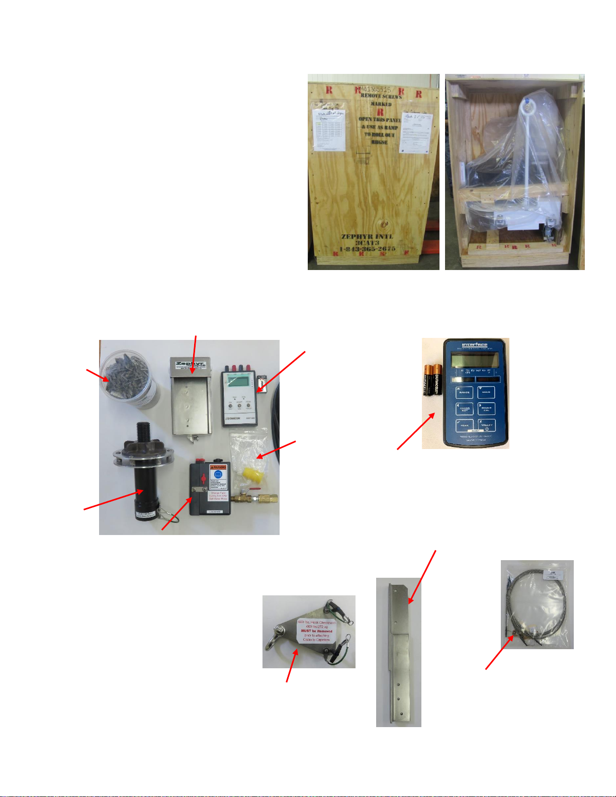
Figure 3 Shipping crate........................................................................................................................6
Figure 4 Loose components................................................................................................................. 6
Figure 5 Misc. Components................................................................................................................. 6
Figure 6 Setting Up..............................................................................................................................7
Figure 7 Upper Upright Bracket assembly............................................................................................ 7
Figure 8 Lubridryer Assembly..............................................................................................................7
Figure 9 Attaching the Load Cell to the Display....................................................................................8
Figure 10 Load cell display terminals...................................................................................................8
Figure 11 Old Style Load Indicator Holder ...........................................................................................8
Figure 12 Load indicator setup.............................................................................................................9
Figure 13 600 lb. Hook Check Adapter ...............................................................................................9
Figure 14 RHGSE Description........................................................................................................... 10
Figure 15 Lubridryer........................................................................................................................... 11
Figure 16 Cable wrapping sequence.................................................................................................. 12
Figure 17 Tensioner Arms.................................................................................................................. 13
Figure 18 Spooler Cutout.................................................................................................................. 14
Figure 19 Proper cable positioning in Rotatub and Spooler................................................................ 14