Zero AEROLYTE PRN 6060-A User manual

NOTICE TO PURCHASERS AND USERS OF OUR
PRODUCTS AND THIS INFORMATIONAL MATERIAL
Clemco proudly provides products for the abrasive blast industry
and is confident that industry professionals will use their knowledge
and expertise for the safe and efficient use of these products.
The products described in this material, and the information
relating to these products, are intended for knowledgeable,
experienced users. It is the responsibility of the user to insure that
proper training of operators has been performed and a safe work
environment is provided.
No representation is intended or made as to: the suitability of the
products described here for any purpose or application, or to the
efficiency, production rate, or useful life of these products. All
estimates regarding production rates or finishes are the
responsibility of the user and must be derived solely from the user’s
experience and expertise, not from information contained in this
material.
It is possible that the products described in this material may be
combined with other products by the user for purposes determined
solely by the user. No representations are intended or made as to
the suitability of or engineering balance of or compliance with
regulations or standard practice of any such combination of products
or components the user may employ.
This equipment is only one component of a cabinet blasting
operation. Other products, such as air compressors, air filters and
receivers, abrasives, equipment for ventilating, dehumidifying, or
other equipment, even if offered by Clemco, may have been
manufactured or supplied by others. The information Clemco
provides is intended to support the products Clemco manufactures.
Users must contact each manufacturer and supplier of products
used in the blast operation for warnings, information, training, and
instruction relating to the proper and safe use of their equipment.
AEROLYTE Pressure Cabinets
Models PRN 6060-A and 7070A G2
O. M. 27789
DATE OF ISSUE: 04/15
REVISION: A, 10/16
© 2016 CLEMCO INDUSTRIES CORP.
One Cable Car Dr.
Washington, MO 63090
Phone (636) 239-4300
Fax (800) 726-7559
www.clemcoindustries.com

AEROLYTE 6060A and 7070A G2 PRESSURE CABINETS Page 1
© 2016 CLEMCO INDUSTRIES CORP. www.clemcoindustries.com Manual No. 27789 Rev. A, 10/16
1.0 INTRODUCTION
1.1 Scope of Manual
1.1.1 These instructions cover set-up, operation,
maintenance, troubleshooting, optional accessories,
and replacement parts for Aerolyte 6060A and 707A G2
pressure dry stripping (non-aggressive media blasting)
pressure cabinets. The instructions cover the operation
of all pull-thru reclaimer and the installation of the dust
collector. The following supplemental manual is
provided for the RPH dust collector.
RPH Dust collectors, manual stock no. ....... 21449
1.1.2 The instructions contain important information
required for safe operation of the cabinet. Before using
this equipment, all personnel associated with the blast
cabinet operation must read this entire manual, and all
accessory manuals to become familiar with the
operation, parts and terminology.
1.2 Safety Alerts
1.2.1 Clemco uses safety alert signal words, based
on ANSI Z535.4-2011, to alert the user of a potentially
hazardous situation that may be encountered while
operating this equipment. ANSI's definitions of the
signal words are as follows:
This is the safety alert symbol. It is
used to alert you to potential physical
injury hazards. Obey all safety
messages that follow this symbol to
avoid possible injury or death.
NOTICE
Notice indicates information that is considered
important, but not hazard-related, if not
avoided, could result in property damage.
CAUTION
Caution indicates a hazardous situation that, if
not avoided, could result in minor or moderate
injury.
W
ARNING
Warning indicates a hazardous situation that, if
not avoided, could result in death or serious
injury.
DANGER
Danger indicatesahazardous situation that,
if not avoided, will result in death or serious
injury.
1.3 General Description
1.3.1 Aerolyte pressure cabinets enclose the blasting
environment to provide efficient blasting while
maintaining a clean surrounding work area. Production
rates are influenced by size of nozzle, compressor
output, working pressure, type and size of media, angle
and distance of the nozzle from the blast surface.
Aerolyte pressure cabinets consist of four major
components:
1. Cabinet Enclosure
2. Reclaimer
3. Blast Machine
4. Dust Collector
Refer to Figure 1 for a typical arrangement and callout
of components. The overall height of the RPH-2 is
approximately 10-feet, 4-inches, and increases to 12-ft
when the top access door is open.
1.4 Theory of Operation
1.4.1 Once the components are correctly setup and
turned on, the cabinet is ready for operation by
actuation of the foot pedal. Fully depressing the foot
pedal pressurizes the blast machine, causing the media
to be propelled through the blast hose and out the
nozzle. After striking the object being blasted, the blast
media, fines, dust, and by-products generated by
blasting, fall through the mesh worktable into the
cabinet hoppers. These particles are then drawn into
the reclaimer for separation. Lightweight dust and fines
remain airborne and are drawn out to the dust collector.
Heavier reusable media fall through the screen into the
reclaimer hopper for reuse. The dust collector traps dust
and fines and discharges clean air. When the foot pedal
is released, blasting stops, the blast machine
depressurizes, and stored media refills the machine.

AEROLYTE 6060A and 7070A G2 PRESSURE CABINETS Page 2
© 2016 CLEMCO INDUSTRIES CORP. www.clemcoindustries.com Manual No. 27789 Rev. A, 10/16
Figure 1
1.5 Blast Machine and Remote Controls
1.5.1 Clemco blast machines (pressure vessels) are
certified to conform to the ASME (American Society of
Mechanical Engineers) Boiler and Pressure Vessel Code,
Section VIII, Division 1. It is the owner’s responsibility to
maintain the integrity of the vessel in accordance with the
requirements of state regulations. Regulations may
include regular inspection and hydrostatic testing as
described in National Board inspection code and
jurisdictional regulations and /or Laws.
WARNING
Welding, grinding, or drilling on the blast
machine could weaken the vessel. Compressed
air pressure could cause a weakened blast
machine to rupture, resulting in death or
serious injury. Welding, grinding, or drilling on
the vessel, without a National Board R stamp,
voids the Clemco ASME certification.
1.5.2 All welding repairs to the vessel must be
performed by certified welders at shops holding a
National Board R Stamp. Welding performed by any
welder not properly qualified per the ASME code voids
the Clemco ASME certification.
1.5.3 Do not exceed the maximum working pressure
rating (PSI) of the blast machine. The maximum
pressure rating is stamped into ASME nameplate which
is welded to the side of the vessel.
WARNING
Excessive compressed air pressure could
cause a blast machine to rupture. To prevent
serious injury or death, do not exceed the rated
pressure of the blast machine.
1.5.4 OSHA does not require pressure relief valves
on blast machines when air compressors supplying air
to the blast machines are built to ASME(1) code and
comply with OSHA(2) regulations. OSHA regulation
Some items rotated for clarity
Blast Nozzle
Reclaimer
Blast Hose
Blast Machine
Light-Lined
Flex Hose
Blo
w
-off Hose
* Pilot Regulator
* Control Panel
Light Assembly
Foot Pedal
Blow-off
Nozzle
Air Intake Stack w/Damper
Exhaust Hose
To muffler on rear cabinet wall
RPH Dust Collector
Dust Collector Damper
Unlined Flex Hose
Externally Adjustable Vortex
Debris
Screen
On-Off Switch
Door Interlock
* Controls vary from those
shown when doors are installed
on both side of cabinet.
Compressed-Air Filter
Attachment fo
r
compressed air suppl
y

AEROLYTE 6060A and 7070A G2 PRESSURE CABINETS Page 3
© 2016 CLEMCO INDUSTRIES CORP. www.clemcoindustries.com Manual No. 27789 Rev. A, 10/16
1910.169 refers to the ASME code when describing the
necessity of pressure relief valves on compressed air
equipment. DO NOT operate blast machines with air
compressors that are not equipped with properly-
functioning pressure relief valves.
(1) American Society of Mechanical Engineers, Boiler and Pressure
Vessel Code, Section VIII, Division 1,
(2) Occupational Safety and Health Administration, 29 CFR 1910, 169.
1.5.5 The piping on the blast machine does include a
relief valve that set to vent at 65 psi. Its only purpose is
to serve as an audible signal that pressure is above
normal pressure settings for non-aggressive media and
delicate substrates.
1.5.6 When the cabinet is setup, the blast machine is
ready to blast by actuating the foot pedal. Pressing the
foot pedal opens the normally closed main inlet
regulator, and closes the normally open outlet valve.
The incoming air pressurizes the blast machine, and
blasting begins. When pressure on the foot pedal is
released, the blast machine depressurizes, and blasting
stops.
1.6 Nozzle Options
1.6.1 Unless otherwise specified at time of order,
cabinets are shipped with a 5/16" orifice, silicon carbide
lined, short venturi nozzle. Optional 1/4" or 3/8" orifice
nozzles are also available. 1/4" nozzles should be used
only when the air supply is limited. Low nozzle velocity
and non-aggressive media make 1/4" nozzles
ineffective except for loose adhering coatings and low
production dry stripping tasks. The chart in Figure 2
shows cfm consumption when nozzles are new. Large
nozzles (3/8" and in some cases larger), should be
limited to tough stripping jobs. High nozzle velocity and
high pressure will cause rapid media breakdown.
COMPRESSED AIR CONSUMPTION *(cfm)
Nozzle AIR PRESSURE (psi)
Orifice 20 25 30 35 40 45
1/4" 25 29 32 36 40 43
5/16" 41 47 53 59 65 71
3/8" 57 66 75 83 92 100
* Figures are approximate and for reference only,
and may vary for different working conditions.
Several variables, including media flow and nozzle
wear affect cfm consumption.
Figure 2
1.7 Dust Collector Options
1.7.1 RPH Dust Collector: The RPH-2 is the
standard dust collector unless another collector is
specified at the time the order is placed. Refer to RPH
dust collector manual number 21449.
1.7.2 HEPA (high-efficiency particulate air) Filter:
HEPA after-filters provide additional filtration and must
be used with a reverse-pulse cartridge collectors when
removing lead coatings or any other toxic materials.
HEPA filters are listed under Optional Accessories in
Section 9.1.
1.8 Blasting Media
1.8.1 Aerolyte Dry Stripping Cabinets are designed to
utilize plastic media and other lightweight non
aggressive reusable media specifically manufactured for
dry stripping. The usable media size range depends on
the nozzle orifice size and reclaimer cleaning rate.
Several factors affecting the reclaimer cleaning rate
include: reclaimer size, air pressure, media/air mixture,
media breakdown, contamination of parts being
cleaned, and humidity.
1.9 Compressed Air Requirements
1.9.1 The size of the compressor required to operate
the cabinet depends on the size of the nozzle and
stripping pressure. See the air consumption table in
Figure 2. Unless specified otherwise, cabinets are
supplied with a 5/16" orifice nozzle. The table in Figure
2 shows air consumption of nozzles when new; it does
not show the recommended compressor size. When the
nozzles are worn, they will consume 70% to 80% more
air. Consult with a compressor supplier for a suggested
compressor size based on the air consumption.
NOTE: A separate air line is required for the optional
reverse-pulse dust collector.
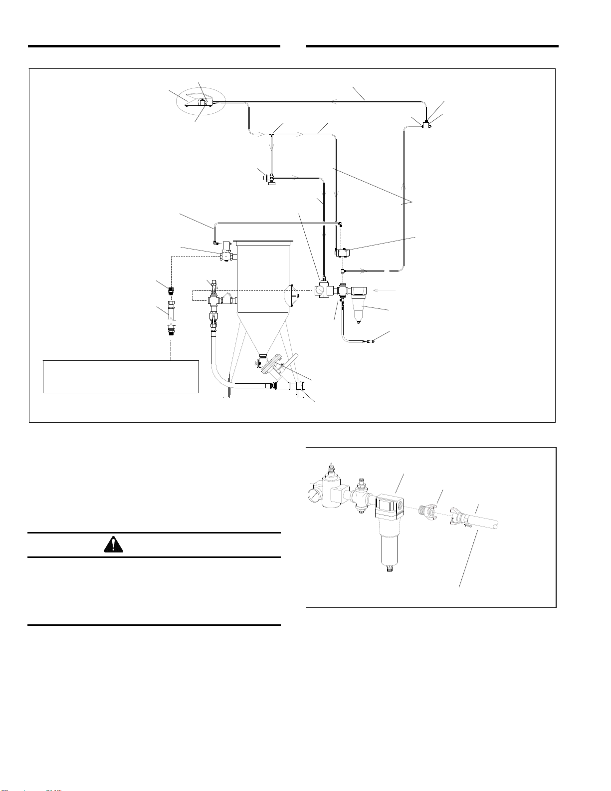
1.9.2 The air filter at the blast machine inlet, removes
condensed water from compressed air. The filter
automatically drains when moisture fills the bowl to a
certain level. Its use is especially important in areas of
high humidity, or when fine-mesh media are used.
Moisture causes media to clump and prevents free flow
through the metering valve. If the filter does not remove
enough moisture to keep media dry and flowing, it may
be necessary to install an air dryer or aftercooler in the
air supply line.

AEROLYTE 6060A and 7070A G2 PRESSURE CABINETS Page 4
© 2016 CLEMCO INDUSTRIES CORP. www.clemcoindustries.com Manual No. 27789 Rev. A, 10/16
1.10 Electrical Requirements
All wiring external to the cabinet is provided by the user
to comply with local electrical codes.
1.10.1 Electrical requirements depend on the size and
phase of the dust collector exhauster motor. NOTE: Full
load amps (FLA) shown below are for the motor only;
the lights draw less than one amp. Standard cabinets
are supplied as follows:
900 cfm reclaimer: 2 HP, 208/230/460V, 3-PH, 60 HZ
Supplied with 230-volt control panel unless 460-volt is
specified at the time the order is placed.
FLA 208/5.5, 230/5.6, 460/2.8.
1.10.2 A control panel and starter are provided with
230-volt controls unless 460-volt is specified on the
order. Power from the user's disconnect has to be wired
to it. Additional wiring information is in Section 2.11. A
wiring schematic is enclosed in the control panel.
2.0 INSTALLATION
2.1 General Installation Notes
2.1.1 To avoid damage to the light assembly and air
intake stack, they are shipped inside the cabinet. Install
the light assembly and intake stack on the outside top of
the cabinet (ref Figure 1), using the adhesive-backed
gasket and fasteners provided. Install the light conduit
and wiring to the control panel, and wire it per the wiring
schematic packed in the panel. Refer to Section 2.11.
W
ARNING
Use an approved ladder or lift and fall
protection when installing or servicing the light
assembly or air intake stack. Do not climb on
top of the cabinet. The cabinet top will not
support body weight and could cause injury.
2.1.2 The cabinet must be placed on a flat level
surface. If the surface is not flat, the cabinet could flex,
causing the door alignment to shift. If the floor is not
level, shim the leg(s) as required to align the doors.
2.1.3 Use the eyebolts on the four top corners to lift
and maneuver the cabinet. Do not lift the cabinet from
the hopper or lower frame.
NOTICE
Do not use a forklift to lift the cabinet from the
hoppers or lower frame. The cabinet hopper is
not designed to support the weight of the
cabinet. The lower frame is designed to support
distributed weight. Using a forklift on the
hoppers or frame may cause damage.
2.1.4 Refer to Figure 1 for the general arrangement
and Figure 4 for the control line schematic. Select a
location where compressed air and electrical service are
available. The cabinet location must comply with OSHA
and local safety codes. Allow for full access to all doors
and service areas and for efficient handling of large
parts. Provide enough clearance in front of the dust
collector to remove the dust drawer without tipping.
Ideally, locate the blast machine directly behind the
cabinet with the blast hose connection toward the
cabinet. The reclaimer may be rotated on the blast
machine to make hose connections with as few bends
as possible. Determine the best location for all
components and position them before making
compressed air connections, electrical connections, and
attaching flex hose.
2.1.5 Refer to the dust collector owner’s manual to
set up the dust collector and prepare it for operation.
2.2 Assemble Blast Machine and Reclaimer
2.2.1 Apply adhesive-backed strip gasket to the top of
the flange on the blast machine. Punch out an opening
at each bolt hole.
2.2.2 If the optional storage segment is used, place it
on the blast machine. The access door should be on the
bottom, and rotated to allow access. Bolt into place.
Apply adhesive-backed gasket to the top flange as
described in Section 2.2.1
2.2.3 Use a lift to raise the reclaimer over the blast
machine assembly, and lower it in place. Attach with
fasteners provided. Note: Optional 1200 cfm and
larger reclaimers are mounted on legs. Slide the
blast machine under the reclaimer and bolt flanges
together.
WARNING
Do not work under the reclaimer while it is
hanging from the lifting device. Severe injury or
death could occur if the reclaimer is released
before it is secured to the blast machine.

AEROLYTE 6060A and 7070A G2 PRESSURE CABINETS Page 5
© 2016 CLEMCO INDUSTRIES CORP. www.clemcoindustries.com Manual No. 27789 Rev. A, 10/16
2.3 Support the Blast Machine
2.3.1 Use chain, cable, or other means to temporarily
support the blast machine and reclaimer during final
assembly.
2.4 Connect Conveying Hose, Figure 3
Refer to Page 31, Figure 35 for hose sizes
Figure 3
2.4.1 Connect the two smallest diameter flexible
conveying hoses between the cabinet hopper transitions
and wye pipe adaptor. It is easier to slip the hose over
the adaptor and to create a tighter seal if the first two or
three inches of wire are removed from the inside of the
hose. Use care not to damage the hose. NOTE: The
hose wire helps dissipate static electricity in the
conveying hose, and also helps ground each segment.
In order for the hose wire to dissipate static electricity,
the wire must touch the metal of each segment. Clamp
the flex hose securely with worm clamps provided.
2.4.2 Connect the intermediate diameter flex hose
between the wye pipe and reclaimer inlet adaptor.
Clamp the flex hose securely with worm clamps
provided.
2.4.3 The largest diameter hose attaches to the
reclaimer outlet, which will be connected later.
2.5 Connect Blow-Off Hose
2.5.1 Attach the 1/2" blow-off hose coming from the
front right cabinet hopper to the compatible fitting on the
blast machine piping, between the air filter and
regulator. Refer to the schematic in Figure 4.
2.6 Connect Blast Hose
WARNING
Hose disconnection while under pressure could
cause serious injury. Use safety lock-pins and
safety cables on all coupling connections to
help prevent hose couplings from accidental
disconnection while under pressure. Lock-pins
and safety cables are listed under Optional
Accessories in Section 9.1.
2.6.1 Connect the blast hose from the lower left side
of the rear cabinet wall to the coupling at the bottom of
the blast machine. Be sure coupling gaskets are in
place and couplings are secured with safety lock-pins.
2.7 Attach Blast Machine Exhaust Hose
2.7.1 Screw the male end of the exhaust hose into
the 1" coupling located on the lower left side of the rear
cabinet wall. Connect the female swivel end to the male
adaptor on the blast machine outlet valve.
2.8 Connect Urethane Control Tubing
2.8.1 Uncoil the 1/8" urethane control tubing, from
under the cabinet. The end of each tubing is numbered
1, 2, 3 or 4. Connect the tubing to the adaptor with the
corresponding number on the pressure regulator,
piping, and 4-way air valve. Refer to the schematic in
Figure 4 to confirm the connections.
2.9 Connect Compressed Air Supply Line(s)
WARNING
Failure to observe the following before
connecting the equipment to the compressed
air source could cause serious injury or death
from the sudden release of compressed air.
• Lockout and tagout the compressed air supply.
• Bleed the compressed air supply line.
Hopper
Transition
Smallest Diameter Hose
Wye Pipe Adaptor
Intermediate Diameter Hose
Largest Diameter Hose
Clamps
Clamps

AEROLYTE 6060A and 7070A G2 PRESSURE CABINETS Page 6
© 2016 CLEMCO INDUSTRIES CORP. www.clemcoindustries.com Manual No. 27789 Rev. A, 10/16
Figure 4
2.9.1 Apply thread sealant to the male threads of an
air fitting that is compatible with the air supply hose
fitting, as noted in Section 2.9.2, and install it onto the 1-
NPT air filter located at the blast machine inlet, as
shown in Figure 5. Note that the style of connection
shown in Figure 5 is for reference only.
WARNING
If twist-on type air hose couplings are used,
they must be secured by safety pins or wires to
prevent accidental disconnection while under
pressure. Hose disconnection while under
pressure could cause serious injury.
Figure 5
2.9.2 Install an isolation valve at the air source to
enable depressurization for service, and connect a 1" ID
or larger air line from the air source to the air filter on the
blast machine. A smaller diameter hose may reduce
blasting efficiency.
1/8Urethane Tubing
Foot Pedal
Door Interlock Valve
In
Out
Out
Compressed Air Inlet
3/8Poly Tubing
Outlet Valve
Media Metering Valve
Blow-off Nozzle
Pressure Regulator
Air Filter
Blast Hose Connection
Tee Unregulated Air
Pilot Regulator
Regulated Air
4-Way Valve
Accessory
Plug
In
Hose Adaptor
Directional arrows on control
lines shows direction of air flow.
1-NPT Air Filter
Air Fitting
Use safety lock-pins to
secure twist-on couplings
Air Supply Hose
Exhaust Hose Assembly
To the 1" coupling located
on left rear of cabinet
1/8Urethane Tubing
Relief
V
a
lv
e

AEROLYTE 6060A and 7070A G2 PRESSURE CABINETS Page 7
© 2016 CLEMCO INDUSTRIES CORP. www.clemcoindustries.com Manual No. 27789 Rev. A, 10/16
WARNING
To avoid the risk of injury from compressed air,
install an isolation valve and bleed-off valve
where the air supply is tapped into the
compressed air system. This enables
depressurization of the compressed-air lines
before performing maintenance.
2.9.3 Refer to the dust collector owner’s manual and
connect a compressed-air line to the pulse manifold.
2.10 Ground Cabinet
2.10.1 To prevent static electricity build up, attach an
external grounded wire from an earth ground to the
grounding lug on the left rear of the cabinet.
2.11 Connect Electrical Service
WARNING
Shorting electrical components could result in
serious electrical shocks, or equipment
damage. Electrical power must be locked out
and tagged out before performing any electrical
work. All electrical work or any work done
inside a control panel or junction box must be
performed by a qualified electrician, and
comply with applicable codes.
All wiring external to the cabinet is provided by the user
to comply with local electrical codes.
2.11.1 Three-Phase Wiring
NOTE: a wiring schematic is packed inside the cabinet’s
control panel. After wiring is completed, keep a copy of
the schematic with the manual for future reference and
for electrical replacement parts.
2.11.1.1 Refer to the wiring schematic stowed inside the
control panel mounted on the cabinet and wire from the
users disconnect to the panel and from the panel to the
dust collector motor, per instruction on the motor data-
plate
2.11.1.2 Check the amperage on initial start up; if the
motor draws excessive amperage, gradually close the
dust collector damper, located on the exhauster outlet
on RPH dust collectors, until the amperage is within the
specifications shown on the motor plate.
2.11.2 Check Motor Rotation
2.11.2.1 After wiring is completed, observe the warning
that follows and check the motor rotation. To check
rotation, turn the On-Off switch ON and quickly turn it
OFF, causing the motor to rotate slowly. Look through the
slots in the motor fan housing where rotation of the fan
can easily be observed. Proper rotation is indicated by
the arrow on the exhauster housing; the fan should
rotate toward the exhauster outlet. If it rotates in reverse,
change the wires as noted on the motor plate to reverse
rotation.
WARNING
Do not look into the exhauster outlet while the
paddle wheel is turning. Injury to the eye or
face could occur from objects being ejected
from the exhauster.
2.12 Anchor Blast Machine
2.12.1 Anchor holes are located in the blast machine leg
pads. When all the components are in their permanent
position, remove the temporary supports and anchor
through the holes to secure the machine to the floor.
2.13 Cabinet Air-Inlet Damper, Refer to Figure 6
2.13.1 The air-inlet damper is located on the top of the
cabinet and must be set to match the cabinet dimensions
and reclaimer size. The air-damper was preset prior to
shipment; confirm the initial setting as noted below.
2.13.2 The label on the damper show the settings in
degrees. The initial setting should align the handle as
noted below.
900 reclaimer..................... align handles to 30 degrees
1200 reclaimer........align handles to 0 degree (full open)
1800 reclaimer........align handles to 0 degree (full open)
Figure 6
Degrees Label
Air-Inlet Damper
Damper Handle
Align handle to degrees as
noted in Section 2.13.2.

AEROLYTE 6060A and 7070A G2 PRESSURE CABINETS Page 8
© 2016 CLEMCO INDUSTRIES CORP. www.clemcoindustries.com Manual No. 27789 Rev. A, 10/16
2.13.3 Loosen the lock nuts and position the damper.
When correctly positioned, tighten the lock nuts to
maintain the setting. Refer to Section 5.6 for adjustment
procedure.
2.14 Final Assembly
2.14.1 Insert a section of 3/8 tubing into the automatic
drain at the bottom of the compressed-air filter and place
the other end into a pail. When the filter automatically
drains, the water will drain into the pail.
2.14.2 Position the foot pedal on the floor at the front of
the cabinet.
2.14.3 A package of five window cover lenses is
supplied with the cabinet. Install a cover lens per
Section 7.2. When the cover lens becomes pitted or
frosted, replace it.
3.0 FIELD INSTALLED ACCESSORIES
3.1 Curtain Installation, Figure 7
3.1.1
Match the curtains to the corresponding wall and
door as shown in Figure 7. Hook the curtains to the J-
Hooks welded along the top of the front, back, and side
walls. Cut openings for the hoses on the lower left rear wall.
Figure 7
3.1.2 Using protectors against the curtains and outer
doors, clamp the door curtains in place. The upper
edges of the door curtains should be even with the outer
edges of the sound proofing panel. Insert a #10 self-
drilling screw with an 11/16OD flat washer through the
grommet holes. Use a screw gun with a 5/16" socket to
attach the door curtains.
3.1.3 For front walls, place the batten strip over the
curtain, and clamp it in position on the front slope above
the break as shown in Figure 7. Match drill .187" (3/16")
diameter holes through the rubber and cabinet front at
each batten hole. To install the batten insert #10-24 x 1
round head machine screws through the cabinet front,
curtain and batten. Install lock washers and nuts from
inside the cabinet and tighten securely.
3.2 Manometer
The optional manometer kit is listed in Section 9.1.
3.2.1 Consistent static pressure is necessary for
precise media separation, as the reclaimer's efficiency is
achieved by a centrifugal balance of air flow, particle
weight, and size. The manometer measures static
pressure. Reclaimer static pressure is set by adjusting
the outlet damper; refer to Section 5.3 to adjust static
pressure. Refer to Section 5.7 for manometer
instructions.
3.3 Armrest
3.3.1 Assemble the armrest and mounting brackets as
shown in Figure 8.
3.3.2 Position the assembly so the armrest is about
even with the bottom of the arm-port opening. Mark one
hole location on the front of the cabinet at each
mounting bracket.
Figure 8
3.3.3 Drill a 3/8" hole at both locations and mount the
armrest using 5/16 cap screw, washers and nuts. Install
the bolts from inside the cabinet to protect the threads
from abrasion, should the armrest need to be removed
at a later date.
J-Hook
No. 10 Self- drill Screw Washer
Nut
Lock Washer
Batten Strip
Machine Screw
5/16 x 1" x Cap Screw,
Flat Washer, Lock
Washer and Nut
Armrest
3/8 x 1" Cap Screw
and Lock Washer

AEROLYTE 6060A and 7070A G2 PRESSURE CABINETS Page 9
© 2016 CLEMCO INDUSTRIES CORP. www.clemcoindustries.com Manual No. 27789 Rev. A, 10/16
3.3.4 Match drill the remaining four bracket holes and
install the remaining fasteners.
3.3.5 Loosen the fasteners on the slotted bracket and
raise or lower the armrest to a comfortable position.
3.4 Track and Turntable Assembly
3.4.1 These instructions cover field installation of the
2000 lb. capacity track and work cart with turntable. If
the track was ordered with the cabinet, it is partially
assembled at the factory. Disregard the instructions that
do not apply. Refer to Figure 9 for arrangement of the
major components.
Figure 9
3.4.2 Install inside track, refer to Figure 10
3.4.2.1 Lay the inside track on the cabinet hoppers and
above the grate as shown in Figure 10.
Figure 10
3.4.2.2 Push the end support bar against the inside
cabinet wall, opposite the door, and insert the angled
tabs on the door end of the track into the two sleeves on
the hopper as shown.
3.4.2.3 Make sure the weight of the track is evenly
distributed over the hoppers and match drill through the
cabinet wall, at the four hole locations in the end support
bar for 3/8 fasteners. If necessary, mark the hole
locations and remove the track for drilling.
3.4.2.4 Secure the inside track to the cabinet with four
3/8-NC cap screw, flat washers, lock washers, and nuts
provided.
3.4.3 Position outside track, refer to Figure 11
3.4.3.1 Place the outside track so it is in-line with the
inside track. Space the track so the top rails (not the
smaller support rails) on the hinged end are approximately
42-inches from the top rails on the inside track.
42-Inches
Figure 11
3.4.4 Attach hinged track, refer to Figure 12
Figure 12
Release Pin (3)
Inside Track
Outside Track
Release Pin (3)
Workcar
Turntable
Angled
Mounting Tabs
Match Drill
4 bolt holes
Insert angled
tabs into hopper
sleeves.
Hinged Track
Doors and Grates Removed for Clarity
Outside Track
End Support
Bar
Hinged Track
Lay hinged track on inside
and outside track supports
1/2 x 1/2
Shoulder Screw
Stock No. 03491
Quick Release Pin
Stock No. 25540
3/8 Lock Nut
Stock No. 03312
Track Supports
Leveling Foot Pads
Leveling Foot Pads

AEROLYTE 6060A and 7070A G2 PRESSURE CABINETS Page 10
© 2016 CLEMCO INDUSTRIES CORP. www.clemcoindustries.com Manual No. 27789 Rev. A, 10/16
3.4.4.1 With the door open, place the hinged track on
the inside and outside track supports, as shown in
Figure 12. Maneuver the outside track as needed to
align the hinge track bolt holes with the outside track bolt
holes, while making sure hinge track is fully resting (with
no gaps) on the track supports.
3.4.4.2 Install 1/2" shoulder screws through both hinged
track pivot-bars and into the holes in the outside track.
Secure with 3/8 lock nuts.
3.4.4.3 Raise or lower the four adjustable foot pads on
the outside track as needed to level it to the hinged track
and inside track.
3.4.4.4 The quick release pin holds the hinge track
when in the raised position, as shown in Figure 12.
3.4.5 Turntable work cart and hinge track
operations, refer to Figure 13
3.4.5.1 Set the workcar on the outside track; the
grooves in the wheels are designed to ride on the top of
the track rails.
3.4.5.2 For shipping purposes, some field installed or
replacement turntables may not be installed in the
workcar. If shipped separately, slide the turntable shaft
through the rubber bearing protector, bearing collar and
bearing. When the turntable shaft is fully seated in the
bearing, use a hex key to tighten the collar on the shaft.
Figure 13
3.4.5.3 Move the workcar toward the track stops until
the hole in the pin bracket is aligned with the hole in the
outside track cross brace. Insert the release pin through
both holes to prevent the workcar from moving. Note: A
similar hole is in one of the inside track cross braces.
Inserting the pin through the workcar and inside track
hole prevents the workcar from moving when inside the
cabinet.
3.4.5.4 When certain the tracks are aligned, level, and
the workcar moves smoothly on all tracks, anchor the
outside track to the floor through the holes in the foot
pads.
3.4.5.5 Raise the hinged track until the locking hole in
the pivot-bars is aligned with the hole in the bracket on
the bottom side of the outside hinge. Install a quick
release pin on both sides of the track to hold it vertical.
WARNING
Always insert pins in both sides of the hinged
track to lock it upright, when it is lifted vertical.
The track could fall if left unlocked and cause
severe injury.
4.0 OPERATION
4.1 Media Loading and Unloading
4.1.1 Media Capacity: Media capacity is approximately
2,0 cubic feet. The machine is full when media reaches
the level of the pop-up valve.
4.1.2 Media Loading: With the exhauster OFF, add
clean dry media by pouring it into the reclaimer hopper
through the reclaimer door. Do not pour media directly
into the cabinet hopper, as over filling may occur.
Overfilling will result in media carryover to the dust
collector and possible blockage in the conveying hose.
Refill only after all media has been recovered from the
cabinet.
4.1.3 Media Unloading: To empty the cabinet and
blast machine of media, turn the exhauster ON blow-off
the cabinet interior and run the exhauster until all media
is recovered from the cabinet. Reduce pressure to 40
psi. Place an empty container, such as a bucket, on the
cabinet grate. Remove nozzle and nozzle washer, close
the door, close the choke valve (Item 1, Figure 33) and
press the foot pedal. Direct media flow into the
container. Empty the container when full or before it is
too heavy to handle, and repeat the process until the
machine is empty. Return the choke valve to the full
open position. Clean the nozzle holder threads and
inspect the threads on the nozzle and nozzle holder
before reinstalling the nozzle washer and nozzle. If
complete purging of media is required, use a vacuum to
clean media residue in cabinet hopper and blast
machine head.
Quick Release Pin
Track Stops
Pin Bracket
Anchor Holes (4 Places)
Quick Release Pin

AEROLYTE 6060A and 7070A G2 PRESSURE CABINETS Page 11
© 2016 CLEMCO INDUSTRIES CORP. www.clemcoindustries.com Manual No. 27789 Rev. A, 10/16
4.2 Loading and Unloading Parts
WARNING
Use solid fixturing to hold heavy parts in place.
Do not remove lift equipment until the part is
adequately supported to prevent movement.
Moving heavy, unsupported parts may cause
them to shift or topple, resulting in severe
injury. This is especially important with the use
of turntables and turntables with tracks.
4.2.1 Load and unload through the door.
4.2.2 Parts must be free of oil, water, grease, or other
contaminants that will clump media or clog filters.
4.2.3 When blasting small parts or objects having small
pieces that could become dislodged and fall off, place an
appropriately-sized screen over the grate (or under the
grate when frequently blasting small parts) to prevent
parts from falling into the hopper.
4.2.4 Close door; the door interlock system will
prevent blasting if door is open.
4.3 Blasting Operation
CAUTION
Always close cabinet, reclaimer and dust
collector doors before blasting. Keep all
doors closed during blasting.
Always use blast gloves.
Avoid pointing the blast nozzle toward the
view window.
Use the blow-off nozzle to blow media off
parts before opening doors.
After blasting, keep doors closed and
exhauster running until the cabinet is clear
of all airborne dust.
Stop blasting immediately if dust leaks are
detected.
4.3.1 Slowly open the air valve on the air supply hose
to the blast machine Check for air leaks on the initial
start up and periodically thereafter.
4.3.2 Turn ON the lights and exhauster. The push-
button switch located on the control panel performs both
functions. Pull the button to start the exhauster.
4.3.3 Load parts.
4.3.4 Close door; the door interlock system will
prevent blasting if the door is open.
4.3.5 Insert hands into gloves.
4.3.6 To blast, hold the nozzle holder or hose just
behind the nozzle holder, point the nozzle toward the
object to be blasted, and apply pressure to the foot
pedal. Blasting will begin almost immediately.
WARNING
Shut down the cabinet immediately if dust
leaks from the dust collector or cabinet. Make
sure dust collector filters are correctly seated
and not worn or damaged. Prolonged
breathing of any dust could result in serious
lung disease or death. Short term ingestion of
toxic dust such as lead, poses an immediate
danger to health. Toxicity and health risk vary
with dust generated by blasting. Identify all
material to be removed by blasting, and obtain
a safety data sheet (SDS) for the media.
4.3.7 Adjust the pilot pressure regulator to the
required blasting pressure, per Section 5.1. The
regulator is located on the left side of the cabinet.
NOTE: Pressure registers on the gauge only while
blasting.
NOTE: When blasting parts off the grate, use a solid
conductive back rest to support the part. Without this
assist, especially with longer blasting operations, the
operator will tire easily from resisting blast pressure, and
static electricity could build up in the ungrounded part
and cause static shocks. Whenever possible avoid
holding small parts that require blasting into the glove.
4.3.8 If an object should fall through the grate, stop
blasting immediately and retrieve it.
4.4 Stop Blasting
4.4.1 To stop blasting, remove pressure from the foot
pedal. The blast machine will depressurize each time
the foot pedal is released.
4.4.2 The blast machine refills with media stored in
the reclaimer each time the foot pedal is released.
Refilling takes approximately 15 seconds.
4.4.3 Use the blow-off nozzle to blow media off
cleaned parts. Allow the exhauster to clear the cabinet
of airborne dust before opening the door.

AEROLYTE 6060A and 7070A G2 PRESSURE CABINETS Page 12
© 2016 CLEMCO INDUSTRIES CORP. www.clemcoindustries.com Manual No. 27789 Rev. A, 10/16
4.4.4 Keep doors closed and exhauster running until
the cabinet is clear of all airborne dust.
4.4.5 Unload parts, shut off the air supply valve, and
switch OFF the lights and exhauster.
4.5 Blasting Technique
4.5.1 Blasting technique is similar to spray painting
technique. Smooth continuous strokes are most
effective. The distance from the part affects size of blast
pattern. Under normal conditions, hold the nozzle
approximately 6" from the surface of the part.
5.0 ADJUSTMENTS
5.1 Blasting Pressure
NOTICE
The relief valve on the blast machine piping is set to
vent at 65 psi. It serves as an audible signal that
pressure is above normal pressure settings for non-
aggressive media and delicate substrates.
5.1.1 The pilot pressure regulator, located on the left
side of the cabinet, enables the user to adjust the
blasting pressure to suit the application. The suitable
pressure for most purposes is around 80 psi. Lower
pressures may be required on delicate substrates, and
will reduce media breakdown. Higher pressure may be
required for difficult blasting jobs on durable substrates,
but will increase media break down. Optimal production
can only be achieved when pressure is carefully
monitored.
5.1.2 Pressure registers on the gauge only while
blasting. While holding the nozzle securely, adjust air
pressure at the pilot regulator, located on the left side of
the cabinet.
5.1.3 To adjust pressure, unlock the knob by pulling it
out as shown in Figure 14, and turn it clockwise to
increase pressure or counter-clockwise to decrease
pressure. Once operating pressure is set, push in on the
knob to lock it and maintain the setting.
5.1.4 If the application requires blasting below 40 psi,
first pressurize the blast machine at 40 psi, and then
turn the pressure to the required setting before blasting
the part. If the initial pressure is below 40 psi, the pop-up
valve may not seal.
Figure 14
5.2 Media Metering Valve
NOTE: The following instructions explain the adjustment
of handle-type FSV metering valve. Knob-type valves
are adjusted by turning the knob clockwise for less
media, or counterclockwise for more media. Separate
manuals are provided with optional valves.
5.2.1 Media flow is adjusted at the metering valve
located at the bottom of the blast machine.
5.2.2 Begin adjustments with the metering valve
closed. Closed. The FSV metering valve is closed when
the handle is turned to either side of center until it hits
the stops.
5.2.3 While the operator is blasting, the machine
tender increases media flow by moving the handle
toward center, no more than 1/4" at a time, allowing time
for the flow to stabilize before readjusting.
5.2.4 Optimum media flow depends on the type and
size of media and blasting pressure, and can best be
determined by experience. Use as little media as possible
while maintaining the maximum cleaning rate. The air/
media mixture should be mainly air. As a rule, the stream
of media coming out of the nozzle should barely discolor
the air when seen against a contrasting background.
5.2.5 Once the correct flow is attained, loosen the
wing nut on the gauge unit and move the handle bolt
spacer against the metering handle. This allows the
handle to be moved (opened or closed) and returned to
the same setting.
Push knob in to lock
Pull knob out to unlock
When viewed from the knob end,
turn clockwise to increase pressure
turn counterclockwise to decrease pressure
Adjustment Knob
Blast Pressure Regulator
Located on top left
side of cabinet

AEROLYTE 6060A and 7070A G2 PRESSURE CABINETS Page 13
© 2016 CLEMCO INDUSTRIES CORP. www.clemcoindustries.com Manual No. 27789 Rev. A, 10/16
5.3 Reclaimer Static Pressure (dust collector
outlet damper)
5.3.1 Constant static-pressure balance is necessary
for precise media separation. Correct static-pressure
varies with the size of reclaimer and the size, weight and
type of media.
5.3.2 Adjust static-pressure by opening (handle inline
with air flow) or closing (handle perpendicular to air flow)
the damper. The damper is located on the outlet of the
reverse-pulse collector. If the damper is not opened
enough far, the poor visibility, and possible media
blockage in the reclaimer will not remove fines, resulting
in dusty media, conveying hose. If the damper is opened
too far, it may cause carryover (usable media carried
into the dust collector) and result in excessive media
consumption. Open only as far as necessary to achieve
dust removal without media carryover.
5.3.3 A manometer is useful when adjusting or
monitoring static-pressure. The optional manometer kit
is listed under Optional Accessories in Section 9.1.
Refer to Section 5.7 for operation. The static pressure
starting point for plastic media should be 2-1/2" to 3".
Run the media through several blast cycles allowing the
reclaimer to function with these settings. Inspect the
media in the reclaimer and fines in the dust collector as
noted in Paragraph 5.3.2. Continue adjusting static-
pressure until optimum media cleaning without carryover
is attained.
5.3.4 If the damper has been adjusted and carryover
or excessive dust in the media continues, the
adjustable vortex cylinder may help by fine-tuning
media separation.
5.4 Externally-Adjustable Vortex Cylinder
The vortex cylinder fine-tunes media separation. Before
adjusting the cylinder, adjust the damper on the dust
collector to increase or decrease static pressure per
Section 5.3. Once the damper is adjusted, adjust the
cylinder.
5.4.1 The vortex cylinder is located atop the reclaimer
where the flex hose connects. Adjustments are made by
loosening the handle's tensioning knob and moving the
handle to achieve the correct setting. When the correct
setting is established, tighten the locking knob to prevent
movement. Start with the lever slightly to the right (about
one o’clock as shown in Figure 15) of the vertical position.
5.4.2 To Remove More Fines: (Too much dust in
media) Raise the cylinder by moving the lever left
toward "COARSE", in 1/4" increments at the indicator
plate. Allow the media to go through several blast cycles
before determining if further adjustment is needed.
5.4.3 To Remove Less Fines: (Excessive usable
media is carried to the dust collector) Lower the vortex
cylinder by moving the lever right toward "FINE", in 1/4"
increments at the indicator plate. NOTE: If the cylinder is
lowered too far, the reclaimer will again begin to allow
usable media to be carried over, and cause abnormally
high static pressure.
Figure 15
5.5 Door Interlocks, Figure 16
WARNING
Never attempt to override the interlock system.
Doing so could result in injury from unexpected
blasting.
5.5.1 The door interlocks disable the blasting control
circuit when either door is open. To enable blasting, the
door interlock switch must be engaged when the doors
are closed. The interlocks are set at the factory and do
not normally require field adjustment unless parts are
replaced. When adjustment is required, proceed as
follows.
5.5.2 Close cabinet doors.
5.5.3 Loosen the actuator bracket screws and
adjusting screw nut. Move the actuator bracket up or
down, and the screw sideways, to center the screw on
the over-travel stop. Tighten the bracket screws.
5.5.4 Turn the adjusting screw in or out as required to
engage the switch without applying excessive pressure
on it. Tighten the adjusting screw nuts.
5.5.5 Test the operation with the doors open and then
again closed. Point the nozzle away from the door
during the tests, and open the door only enough to
disengage the interlock switch. The interlocks should
stop the blasting when the doors are opened, and permit
blasting when the doors are closed. NOTE: Negative
Remove more fines
from media by
moving the handle
farther to the left
Remove less
fines by moving
the handle farther
to the right
Tensioning Knob

AEROLYTE 6060A and 7070A G2 PRESSURE CABINETS Page 14
© 2016 CLEMCO INDUSTRIES CORP. www.clemcoindustries.com Manual No. 27789 Rev. A, 10/16
pressure inside the cabinet may cause the doors to flex
inward. Tests should be performed with the exhauster
running.
Figure 16
5.6 Cabinet Air-Inlet Damper (cabinet static
pressure)
5.6.1 Once the inlet is initially set per Section 2.13, it
seldom requires readjustment. The initial setting
produces approximately .5to .75of static pressure in
the cabinet enclosure. Do not confuse cabinet static
pressure with reclaimer static pressure which is
controlled by the dust collector damper, as noted in
Section 5.3. Reclaimer pressure must be set before
cabinet pressure.
5.6.2 Using a manometer (as noted in Section 5.7 and
listed in Section 9.1) is the most accurate method of
monitoring and adjusting cabinet pressure. Following the
instructions packed with the manometer, start the
exhauster and insert the needle into a glove, and adjust
pressure using the inlet damper. Open the damper
farther to decrease static pressure or close it farther to
increase pressure.
5.6.3 If a manometer is not available, use the gloves
as an indicator. With the exhauster running, the gloves
should be inflated, but not elevated off the grate.
5.7 Optional Manometer
NOTE: These instructions show several methods of
taking static pressure readings (negative pressure) on
cabinet reclaimers using a flexible tube manometer. Use
the method best suited for the application. The
instruction explains the processes for taking periodic
readings and shows how to permanently install the
manometer for taking frequent readings. Permanent
fittings should be installed when rigid ducting is used, or
when the manometer installation is permanent. Use
silicone sealer or other sealant to seal around the fitting
to prevent leaks. The fitting should be capable of being
capped when the manometer tube is removed. Capping
the fitting will prevent leaks that alter the reclaimer’s
separation efficiency. The readings are reference points
so it doesn’t matter where the readings are taken as
long as they are always taken at the same location.
Taking readings at different locations could produce
different results. Static pressure readings at the door are
generally 0.5" to 1" lower than those taken above the
reclaimer.
5.7.1 Refer to directions packed with the manometer
for preparation and operating instructions for the
manometer.
5.7.2 Connect one end of the 3/16" ID tubing to one of
the tubing connectors (elbow) at the top of the
manometer, by pushing it over the barbed adaptor.
5.7.3 Leave the needle protector on the needle and
insert the needle into the other end of the tubing. The
ends of the tubing must fit tight on the manometer and
needle; leaks will give inaccurate readings.
5.7.4 Open both manometer valves (elbows) per the
instructions provided with the manometer.
5.7.5 Magnets on the manometer hold it in position on
the reclaimer body. The manometer must be vertically-
plumb so the fluid is level on both sides.
5.7.6 Adjust the slide rule to align the zero with the
fluid level. Refer to Figure 18.
5.7.7 Needle placement: Ref. Figure 17.
5.7.7.1 Taking readings in the flex hose: Remove the
needle protector, and insert the needle into the flex hose
approximately 8" from the top of the reclaimer.
5.7.7.2 Taking readings at the reclaimer door: Open
the reclaimer fill door, remove the needle protector and
place the needle so the point is inside the door opening.
Carefully close the door on the needle. The side of the
needle will embed into the rubber, creating an airtight
seal.
Over-travel Stop
Adjusting Screw Nut
Loosen, and move sideways to
center the adjusting screw on the
over-travel stop.
Adjusting Screw
Adjust the screw to depress the
valve stem when door is closed.
Actuator Adjusting Bracket
Loosen the bracket screws, and
move the bracket up or down to
center the adjusting screw on the
over-travel stop.
Bracket Screws
Cabinet Door

AEROLYTE 6060A and 7070A G2 PRESSURE CABINETS Page 15
© 2016 CLEMCO INDUSTRIES CORP. www.clemcoindustries.com Manual No. 27789 Rev. A, 10/16
Figure 17
5.7.8 Turn the exhauster ON. The negative (static)
pressure will move fluid in the tube.
NOTE: Readings must be taken with the cabinet
doors open, and with the exhauster running.
5.7.9 To find the static pressure, add the number of
inches the fluid travels up one column to the inches the
fluid travels down the other column. Refer to the
example in Figure 18.
5.7.10 After the readings are taken, replace the needle
protector. Close the manometer valves and store the
manometer in the original container in a clean area.
Note: If the manometer installation is permanent, the
manometer may remain on the reclaimer body after the
valves are closed.
Figure 18
8
Pull-thru reclaimers only.
Insert the needle into
straight section of flex
hose, about 8-inches
above the top of the
reclaimer.
The manometer must be vertical when
taking pressure readings.
Place the needle so the
point is inside the door
opening. Carefully close
the door on the needle.
With the exhauster OFF,
slide the rule to align the
zero with the fluid level.
In the example shown, fluid traveled up
the right column 1-3/4 inch,
and down the left column 1-3/4 inch.
Static pressure is determined by adding
the columns together. In the example,
the static pressure is 3-1/2 inches.
To obtain the pressure reading: With the
exhauster ON, add the number of
inches the fluid travels up one column,
to the inches the fluid travels down the
other column. The total is the static
pressure reading.
Reclaimers are for reference and
may differ from those shown.
For taking frequent readings,
install a permanent fitting in
the reclaimer wall, just below
the inner cone as shown.

AEROLYTE 6060A and 7070A G2 PRESSURE CABINETS Page 16
© 2016 CLEMCO INDUSTRIES CORP. www.clemcoindustries.com Manual No. 27789 Rev. A, 10/16
6.0 PREVENTIVE MAINTENANCE
NOTE: To avoid unscheduled downtime, establish an
inspection schedule. Inspect all parts subjected to media
contact, including; nozzle, media hose, flex hose, in
addition to all items covered in this section. Adjust
frequency of inspections as needed based on usage,
type of media, and condition of parts being blasted.
6.1 Daily
6.1.1 Check media level in reclaimer and refill as
necessary.
6.1.2 Check reclaimer debris screen for debris. The
screen is accessible through the reclaimer door. With
the exhauster OFF, remove the screen and empty it
daily or when loading media. Empty the screen more
often if part blasted causes excessive debris. Do not
operate the machine without the screen in place,
oversized byproduct from blasting could plug the nozzle.
6.1.3 Empty the compressed-air filter drain pail at
least once a day, and more often if needed. Moist air
inhibits the flow of media. Drain the air line and receiver
tank regularly. If the filter does not remove enough
moisture to keep media dry and flowing, it may be
necessary to install an air dryer or aftercooler in the
compressed-air supply line.
6.1.4 Refer to the dust collector owner’s manual and
empty dust containers. Adjust intervals based on filling
rate.
6.1.5 Refer to the dust collector owner’s manual and
drain the pulse manifold at the end of each shift.
6.2 Weekly
6.2.1 Make sure that couplings are secure and lock
pins and safety cables are in place.
6.2.2 Check coupling gaskets, couplings, and nozzle
holders for leaks and wear. Replace as necessary.
6.2.3 Inspect nozzle for wear. Replace when orifice
diameter is worn 1/16” larger than original size. Replace
the nozzle washer when worn.
6.2.4 While blasting have someone inspect all
external piping, hoses, valves, and couplings for air
leaks. If leaks are found repair immediately.
6.2.5 While blasting have someone check the blast
machine for air leaks. If leaks are found around the pop-
up valve, inspection door, or pipe fittings at the bottom of
the cone, stop blasting immediately and repair or
replace worn parts. If leaks are not identified and
corrected, abrasive erosion could cause irreparable
damage to the blast machine.
6.2.6 Inspect the blast hose for wear and thin spots by
pinching it every 6 to 12 inches. Soft spots mean the
hose is worn. The first sign of wear is usually along the
outside radius where the hose bend just behind the
nozzle holder. Replace the hose as soon as soft spots
are noted. Couplings will not safely grip worn hose,
and may detach under pressure.
6.2.7 Inspect gloves for wear. The first sign of
deterioration may be excessive static shocks. Replace
as needed per Section 7.1.
6.2.8 Inspect flex hoses for wear.
6.2.9 Inspect view window cover lens, Replace as
needed per Section 7.2.
6.2.10 During operation, inspect cabinet door seals
for media leaks.
6.3 Monthly
6.3.1 Inspect reclaimer wear plate for wear. Replace
as necessary per section 7.9.
6.3.2 Inspect reclaimer door gasket for wear or
damage.
6.4 Dust Collector
Reverse-pulse dust collectors are covered in a separate
manual. Refer to Section 1.1.1.

AEROLYTE 6060A and 7070A G2 PRESSURE CABINETS Page 17
© 2016 CLEMCO INDUSTRIES CORP. www.clemcoindustries.com Manual No. 27789 Rev. A, 10/16
7.0 SERVICE MAINTENANCE
WARNING
Failure to wear approved respirators and eye
protection when servicing dust-laden areas of
the cabinet and dust collector and when
emptying the dust collector could result in
serious eye irritation and lung disease or death.
Toxicity and health risk vary with type of media
and dust generated by blasting. Identify all
material to be removed by blasting, and obtain
a safety data sheet (SDS) for the blast media.
7.1 Gloves
7.1.1 Special static-dissipating gloves are provided for
operator comfort. It will be necessary to change gloves
periodically as they wear. The first sign of deterioration
may be excessive static shocks.
7.1.2 Band-clamp type: Band-clamp type gloves are
held in place by metal band-clamps on the inside of the
cabinet. To replace, loosen the clamps with a
screwdriver, replace the gloves, and tighten the clamps.
7.1.3 Quick-Change type, clampless installation:
Quick-change gloves are held in place using spring rings
sewn into to the attachment end of the glove. To install,
insert the glove into the arm port, so one spring is on the
inside of the port and the other is on the outside,
sandwiching the arm port between both spring rings.
7.2 View Window Cover Lens
7.2.1 Rapid frosting of the view window can be
avoided by directing ricocheting media away from the
window, and by installing a cover lens on the inside
surface of the window. Using cover lenses prolongs the
life of the view window.
7.2.2 The best way to install a cover lens is to remove
the window from the cabinet. If, for some reason, it is not
practical to remove the window, the lens may be applied
with the window glass in place.
7.2.3 To install a cover lens, carefully remove the
adhesive backing making sure the adhesive remains on
the lens, and apply the lens to the clean, dry, inner
surface of the view window. When the cover lens
becomes pitted or frosted, replace it.
7.3 Blast Hose and Nozzle, Refer to Figure 19
7.3.1 When replacing blast hose make sure the hose
is square cut and that it is fully inserted into the nozzle
holder and coupling until it seats tightly against the
shoulder in the holder and coupling. Make sure correctly
sized screws are used to secure the nozzle holder and
blast hose coupling. Screws should not penetrate the
inside of the blast hose.
7.3.2 Replace the nozzle when its inside diameter has
increased by 1/16", or sooner if pressure diminishes
noticeably. Make sure the nozzle washer is in good
condition and in place before screwing the nozzle into
the nozzle holder. Make sure the nozzle is screwed
tightly into the nozzle holder; if nozzle is not tight against
the nozzle washer, thread erosion will occur and nozzle
will fuse to nozzle holder.
Figure 19
Blast Hose
Make sure hose is fully
seated against nozzle
holder and coupling
Make sure end of blast hose
is squarely cut like this,
not like this
Make sure nozzle washer is in
good condition and is in place
Screw nozzle tightly into nozzle
holder. Make sure nozzle
compresses the washer to
create tight seal
Make sure coupling screws are secure
but does not penetrate into the hose ID
Nozzle Holder
Nozzle Washer
Nozzle
Coupling Screws

AEROLYTE 6060A and 7070A G2 PRESSURE CABINETS Page 18
© 2016 CLEMCO INDUSTRIES CORP. www.clemcoindustries.com Manual No. 27789 Rev. A, 10/16
7.4 View Window Replacement
WARNING
Do not use plate glass for replacement view
windows. Plate glass shatters on impact and
could cause severe injury. Use only genuine
replacement parts.
7.4.1 Remove the two window frame nuts located on
the upper edge of the window frame, and swing the
window frame open. NOTE: If the frame is to remain
open, for cleaning or other reasons, remove it per
Section 7.6.
7.4.2 Remove the old window.
7.4.3 Inspect the window frame gaskets, on both the
window frame and on the cabinet. If either gasket is
damaged, replace it per section 7.5.
7.4.4 Install view window cover lens per Section 7.2.
7.4.5 Set the new window (cover lens down) squarely
over the window opening, making sure that all edges of
the window are centered and overlapping the window
gasket, and that the window is resting on the window
support tabs.
7.4.6 Swing the window frame into place and tighten
the frame nuts.
7.5 Window Gasket Replacement, Figure 20
7.5.1 Inspect the gaskets when changing the view
window. Replace the window frame gasket and cabinet
window opening gasket at the first sign of media
leakage around the view window, or if gaskets are worn
or otherwise damaged.
7.5.2 Remove the window and window frame per
Section 7.6.
7.5.3 Remove all the old gasket material and clean
the surfaces of the cabinet and window frame.
7.5.4 Peel a short section of adhesive backing from
the 5/16-thick strip gasket, and adhere the gasket to
the center of the top edge of the window opening as
shown in Figure 20. Peel additional backing as needed,
and work the strip around the radius of each corner,
pressing it firmly to bond. Trim the gasket to fit and
compress the ends to seal.
Figure 20
7.5.5 Using 5/32-thick strip gasket, repeat the
process on the underside of the window frame.
7.5.6 Trim around the window frame bolts slots, as
needed.
7.6 Window Frame Removal, Figure 21
7.6.1 Remove the two window frame nuts located on
the upper edge of the window frame, and swing the
window frame open.
Figure 21
7.6.2 Remove the window to prevent breakage.
Pivot the frame up or down
until tension is removed
from the hinges.
Cabinet Front
Window Frame
5/32x 3/4Gasket
5/16x 3/4Gasket
Support Tabs
Slide the frame to the right
to separate the hinges.
Support Tabs

AEROLYTE 6060A and 7070A G2 PRESSURE CABINETS Page 19
© 2016 CLEMCO INDUSTRIES CORP. www.clemcoindustries.com Manual No. 27789 Rev. A, 10/16
7.6.3 Pivot the window frame up or down until tension
is off the frame hinges.
7.6.4 To remove, slide the frame to the right. The
hinges separate as shown in Figure 21.
7.6.5 Replace the frame in reverse order. Align the
top bolt holes with the bolts; slide the frame as
necessary.
7.6.6 Set the window squarely over the window
opening, making sure that all edges of the window are
centered and overlapping the window gasket, and that
the window is resting on the window support tabs.
7.6.7 Swing the window frame into place and tighten
the frame nuts.
7.7 Pop-up Valve Replacement
7.7.1 Empty the machine of media as described in
Section 4.1.3.
7.7.2 Depressurize the blast machine, and lockout
and tagout the compressed air supply.
WARNING
Failure to observe the following procedure
before performing any maintenance could
cause serious injury or death from the sudden
release of compressed air.
Depressurize the media chamber
Lockout and tagout the compressed air
supply.
Bleed the air supply line to the media
chamber.
7.7.3 To gain access to the pop-up valve, remove the
inspection door assembly.
7.7.4 Use a short pipe wrench to unscrew the pop-up
valve guide as shown in Figure 22, by turning it
counterclockwise. Remove the pop-up valve and guide
from the machine.
7.7.5 Slide the new pop-up valve over the guide, and
then screw the valve guide (with the pop-up valve on it)
into position inside the machine. Tighten the guide
wrench-snug, but not wrench-tight. Over-tightening the
guide will make it difficult to remove next time the pop-
up valve needs replacement.
Figure 22
7.7.6 Put a new gasket on the inspection door, then
bolt the door onto the machine.
7.8 Pop-up Valve Seat Replacement
7.8.1 The easiest method to replace the rubber pop-
up seat is through the reclaimer access door. If for any
reason replacement cannot be made through the
reclaimer, observe the warning in Section 7.7, and
empty the machine and bleed the air supply line.
Remove the inspection door assembly and work through
the opening.
7.8.2 Remove the old seat by using a finger,
screwdriver, or similar object, to work the seat out of the
retainer groove.
7.8.3 Push the new seat all the way through the port
and then fit it into the groove. For the last few inches,
pull up on the seat and allow it to "pop" into position.
7.9 Reclaimer Wear-Plate Replacement
7.9.1 Remove the reclaimer inlet adaptor and old
wear plate. The wear plate is held in place with screws
attached from the outside of the reclaimer; remove the
screws and pull out the wear plate from the reclaimer
inlet.
7.9.2 Angle the new wear plate into reclaimer inlet
until it is in position with the straight end at the reclaimer
inlet. Using a board or similar object for leverage, pry
the wear plate against the inner wall of the reclaimer.
While forcing the wear plate against the reclaimer wall,
install sheet metal screws through the old screw holes
to secure. Caulk seems between the wear plate and
reclaimer to prevent rapid wear in those areas.
Loosen
Tighten
Pop-up Guide
Pop-up Valve
This manual suits for next models
1
Table of contents
Other Zero Industrial Equipment manuals
Popular Industrial Equipment manuals by other brands

Dover
Dover DESTACO ROBOHAND RPS Series Service manual

Blastrac
Blastrac EBE 500 S operating instructions

Biocontrol
Biocontrol topcat Instructions for use

Pfannenberg
Pfannenberg PWI 6152 Series operating manual

PIETRO FIORENTINI
PIETRO FIORENTINI KSI/1 manual

Laguna Tools
Laguna Tools Robland X31 Owner's/assembly manual

SCHUNK
SCHUNK LDM-ES-0100 Assembly and operating manual

Alemite
Alemite 8592 Service guide

ChipBLASTER
ChipBLASTER STANDARD UNIT D30-80-1 Installation, operation and service manual

SSP
SSP EDI Series operating manual

Hoffmann
Hoffmann GARANT VG Basic instruction manual

SCHUNK
SCHUNK TANDEM KRP3 Translation of original operating manual