Zero Pulsar Plus lll-S User manual

Pulsar
®
Plus III-S, Pulsar
®
Plus III-S6
Pulsar® Plus VI-S
Suction Blast Cabinets
O. M. 30421
DATE OF ISSUE: 08/21
REVISION:
© 2021 CLEMCO INDUSTRIES CORP.
One Cable Car Dr.
Washington, MO 63090
Phone (636) 239-4300
Fax (800) 726-7559
Email: info@clemcoindustries.com
www.clemcoindustries.com
NOTICE TO PURCHASERS AND USERS OF OUR
PRODUCTS AND THIS INFORMATIONAL MATERIAL
Clemco proudly provides products for the abrasive blast industry
and is confident that industry professionals will use their knowledge
and expertise for the safe and efficient use of these products.
The products described in this material and the information
relating to these products are intended for knowledgeable,
experienced users. It is the responsibility of the employer to
ensure that proper training of operators has been performed and
a safe work environment is provided.
No representation is intended or made as to the suitability of the
products described here for any purpose or application, or to the
efficiency, production rate, or useful life of these products. All
estimates regarding production rates or finishes are the
responsibility of the user and must be derived solely from the user’s
experience and expertise, not from information contained in this
material.
It is possible that the products described in this material may be
combined with other products by the user for purposes determined
solely by the user. No representations are intended or made as to
the suitability of, engineering balance of, or compliance with
regulations or standard practice of any such combination of products
or components the user may employ.
This equipment is only one component of a cabinet blasting
operation. Other products, such as air compressors, air filters and
receivers, abrasives, equipment for ventilating or dehumidifying, or
other equipment, even if offered by Clemco, may have been
manufactured or supplied by others. The information Clemco
provides is intended to support the products Clemco manufactures.
Users must contact each manufacturer and supplier of products
used in the blast operation for warnings, information, training, and
instruction relating to the proper and safe use of their equipment.

PULSAR® PLUS III-S, III-S6, and VI-S SUCTION BLAST CABINETS Page 1
© 2021 CLEMCO INDUSTRIES CORP. www.clemcoindustries.com Manual No. 30421
1.0 INTRODUCTION
1.1 Scope of Manual
1.1.1 These instructions cover setup, operation,
maintenance, troubleshooting, optional accessories, and
replacement parts for the following Pulsar® Plus Suction
Blast Cabinets:
Pulsar® Plus III-S with 300 cfm power module
Pulsar® Plus III-S6 with 600 cfm power module
Pulsar® Plus VI-S with 600 cfm power module
1.1.2 The instructions contain important information
required for safe operation of these cabinets. Before
using these cabinets, all personnel associated with their
operation must read this entire manual and all accessory
manuals to become familiar with the cabinets’ operation,
parts, and terminology.
1.2 Safety Alerts
1.2.1 Clemco uses safety alert signal words, based on
ANSI Z535.4-2011, to alert the user of a potentially
hazardous situation that may be encountered while
operating this equipment. ANSI's definitions of the signal
words are as follows:
This is the safety alert symbol. It is
used to alert you to potential physical
injury hazards. Obey all safety
messages that follow this symbol to
avoid possible injury or death.
Notice indicates information that is considered
important, but not hazard-related, if not
avoided, could result in property damage.
Caution indicates a hazardous situation that, if
not avoided, could result in minor or moderate
injury.
Warning indicates a hazardous situation that, if
not avoided, could result in death or serious
injury.
Danger indicates a hazardous situation that, if
not avoided, will result in death or serious
injury.
1.3 Table of Contents
SUBJECT SECTION LOCATION
INTRODUCTION ....................................................... 1.0
Scope of Manual ........................................................ 1.1
Safety Alerts ............................................................... 1.2
Table of Contents ....................................................... 1.3
General Description ................................................... 1.4
Theory of Operation ................................................... 1.5
Control-Console Functions ........................................ 1.6
Cabinet and Power-Module Controls and Functions ... 1.7
Nozzle Options ........................................................... 1.8
HEPA (high-efficiency particulate air) Filter ............... 1.9
Reclaimer Options ................................................... 1.10
Blasting Media ......................................................... 1.11
Compressed-Air Requirements ................................ 1.12
Electrical Requirements ........................................... 1.13
INSTALLATION ......................................................... 2.0
General Installation Notes .......................................... 2.1
Electrical and Tubing Connections from
the Power Module to the Cabinet ........................... 2.2
Connect Compressed-Air Supply Line ....................... 2.3
Ground the Cabinet and Power Module .................... 2.4
Connect Electrical Service ......................................... 2.5
Connect Media Hose and Air Hoses .......................... 2.6
Connect Conveying (flex) Hose ................................. 2.7
Set Air-Inlet Damper .................................................. 2.8
Final Assembly ........................................................... 2.9
FIELD INSTALLED ACCESSORIES ........................ 3.0
Aluminum Oxide (aggressive media) Kit .................... 3.1
Cabinet Curtains Installation ...................................... 3.2
U-Tube Manometer .................................................... 3.3
HEPA Afterfilter .......................................................... 3.4
OPERATION .............................................................. 4.0
Season Filter Cartridge .............................................. 4.1
Media Loading and Media Capacity .......................... 4.2
Media capacity ..................................................... 4.2.1
Media loading ...................................................... 4.2.2
Media Unloading ........................................................ 4.3
Loading and Unloading Parts ..................................... 4.4
Blasting Operation ..................................................... 4.5
Blasting Technique .................................................... 4.6
Stop Blasting .............................................................. 4.7
Shutdown ................................................................... 4.8
ADJUSTMENTS ........................................................ 5.0
Blasting Pressure (pilot regulator) ............................. 5.1
Air Jet ......................................................................... 5.2
Media-Air Mixture ....................................................... 5.3

PULSAR® PLUS III-S, III-S6, and VI-S SUCTION BLAST CABINETS Page 2
© 2021 CLEMCO INDUSTRIES CORP. www.clemcoindustries.com Manual No. 30421
Reclaimer Static Pressure (exhaust damper) ............ 5.4
Cabinet Height – Lift Legs .......................................... 5.5
Door Interlocks ........................................................... 5.6
Dustbin Interlock ......................................................... 5.7
Dust-Collector Pulse Pressure ................................... 5.8
Digital Pulse-Control Timer ........................................ 5.9
Operating principles ............................................. 5.9.1
Resetting pulse OFF time .................................... 5.9.2
Reset pulse ON time to factory setting ............... 5.9.3
Reset timer functions to factory “A” setting .......... 5.9.4
Reset timer subranges to factory settings ............ 5.9.5
Cabinet Air-Inlet Damper .......................................... 5.10
Using the Manometer to Set Static Pressure ............ 5.11
PREVENTIVE MAINTENANCE ................................. 6.0
Inspection Notes ......................................................... 6.1
Daily Inspection and Maintenance Before Blasting ..... 6.2
Check media level ................................................ 6.2.1
Inspect reclaimer debris screen and door gasket ... 6.2.2
Drain compressed-air filter ................................... 6.2.3
Inspect dustbin ..................................................... 6.2.4
Daily Inspection During Blasting ................................ 6.3
Inspect cabinet for dust leaks .............................. 6.3.1
Check exhaust air for dust ................................... 6.3.2
Drain pulse reservoir (at end of day) ..................... 6.3.3
Weekly Inspection and Maintenance Before Blasting ... 6.4
View-window cover lens ....................................... 6.4.1
Gloves .................................................................. 6.4.2
BNP® gun assembly ............................................. 6.4.3
Media hose ........................................................... 6.4.4
Dust-collector’s inline filter ................................... 6.4.5
Weekly Inspection During Blasting ............................. 6.5
Flex hoses ............................................................ 6.5.1
Monthly Inspection and Maintenance ......................... 6.6
Reclaimer wear plate and liners ........................... 6.6.1
Additional Dust-Collector Cartridge Pulsing ............... 6.7
SERVICE MAINTENANCE ......................................... 7.0
Gloves Replacement ................................................... 7.1
Quick-Change Gloves and Glove Mounts ................... 7.2
BNP® Gun Assembly ................................................... 7.3
View-Window Cover Lens ........................................... 7.4
View-Window Replacement ........................................ 7.5
Window-Gasket Replacement ..................................... 7.6
Window-Frame Removal ............................................. 7.7
LED Light Assembly .................................................... 7.8
Tube-Lock Fittings ....................................................... 7.9
Servicing Pneumatic Inlet Assembly ......................... 7.10
Replacing Reclaimer Wear Plate .............................. 7.11
300 cfm reclaimer with wielding-on top ............... 7.11.1
600 cfm reclaimer with bolt-on top ...................... 7.11.2
Replacing or Installing Rubber Reclaimer Liners ...... 7.12
Removing or Replacing Reclaimer Inlet Baffle ......... 7.13
Replacing Filter Cartridge .......................................... 7.14
Seasoning Filter Cartridge ......................................... 7.15
Clean Dust-Collector’s Inline Filter ............................ 7.16
Clean Dust-Collector’s Snubber Fittings ................... 7.17
Diaphragm Pulse Valve ............................................. 7.18
TROUBLESHOOTING – PNEU. and MECHANICAL ..... 8.0
Poor visibility/dusty media .......................................... 8.1
Abnormally high media consumption .......................... 8.2
Reduction in blast cleaning rate ................................. 8.3
Plugged nozzle ........................................................... 8.4
Media bridging ............................................................ 8.5
Media surge ................................................................ 8.6
Blockage in media hose ............................................. 8.7
Poor suction in media hose ........................................ 8.8
Air only (no media) from nozzle .................................. 8.9
Blowback through media hose ................................. 8.10
Blasting does not begin when foot pedal is pressed ....... 8.11
Blasting continues after releasing foot pedal ............ 8.12
Media buildup in cabinet hopper ............................... 8.13
Static shocks ............................................................. 8.14
Dust or media leaking from cabinet .......................... 8.15
Dust leaking from dust collector ............................... 8.16
Dust collector does not pulse ................................... 8.17
Dust-collector pulse is steady stream of air .............. 8.18
Dust-collector differential gauge is consistently high ... 8.19
TROUBLESHOOTING - ELECTRICAL ........................ 9.0
Green pushbutton does not illuminate ......................... 9.1
Dust-collector exhauster motor does not start ............ 9.2
Lift legs do not move .................................................. 9.3
Blasting does not begin when foot pedal is pressed ........ 9.4
Foot pedal not working ............................................... 9.5
Blast solenoid valve not working ................................ 9.6
Poor visibility/dusty media .......................................... 9.7
Cabinet LED light does not turn ON ........................... 9.8
ACCESSORIES and REPLACEMENT PARTS ...... 10.0
Optional Accessories ................................................ 10.1
Pulsar III-S and VI-S Cabinet Assembly ................... 10.2
Cabinet Control Console .......................................... 10.3
View Window Assembly ........................................... 10.4
Metering Valve .......................................................... 10.5
Gloves and Glove Mounts ........................................ 10.6
LED Light Assembly ................................................. 10.7
BNP® Gun and Feed Assembly ................................ 10.8
Pneumatic Controls and Parts .................................. 10.9
Reclaimer, Pulsar III 300 CFM ............................... 10.10
Reclaimer, Pulsar VI, 600 CFM .............................. 10.11
Dust Collector Assembly ........................................ 10.12
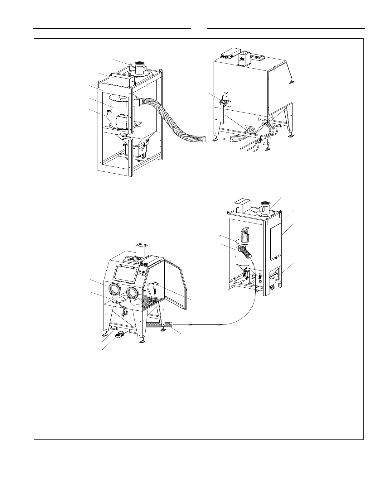
1.4 General Description
1.4.1 The Pulsar Plus cabinets encloses the blasting
environment to provide efficient blasting while maintaining a
clean surrounding work area. Production rates are
influenced by size of air jet and nozzle, compressor output,
working pressure, type and size of media, and angle and
distance of the nozzle from the blast surface. Pulsar Plus
Suction Cabinets consist of two major components.
1. Cabinet Enclosure
2. 300 cfm or 600 cfm Power Module
Refer to Figure 1 for arrangement and primary
components of the cabinet and power module.

PULSAR® PLUS III-S, III-S6, and VI-S SUCTION BLAST CABINETS Page 3
© 2021 CLEMCO INDUSTRIES CORP. www.clemcoindustries.com Manual No. 30421
Figure 1
PULSAR III-S CABINET ENCLOSURE
Refer to Section 2.0 for setup instructions and additional components.
Cabinet and power module shown farther apart than normal for clarity.
Arrange cabinet and power module within space provided, keeping hoses as straight as possible.
Power module may be rotated and spaced within limits of cords and hoses.
Power Lift-Leg
Assembly
Lifting Eye
Reclaimer
Power Module
Dust Collector
Reclaimer Inlet
Flex Hose
Between cabinet hopper and reclaimer inlet.
Arrows show directions of air flow.
Forklift Slots
Filter Cartridge
Access Door
Exhauster Motor
Dustbin
Foot Pedal
BNP® Blast Gun
Glove Ports
Blast Gloves
PULSAR VI-S POWER MODULE
Refer to Figure 6 for additional
power module components.
Refer to Figure 5 for additional
cabinet components.
PULSAR VI-S CABINET ENCLOSURE
Back View
Refer to Figure 5 for additional cabinet
components.
Media Fill Door
Reclaimer
PULSAR III-S POWER MODULE
Refer to Figure 6 for additional
power module components.
Exhaust Damper

PULSAR® PLUS III-S, III-S6, and VI-S SUCTION BLAST CABINETS Page 4
© 2021 CLEMCO INDUSTRIES CORP. www.clemcoindustries.com Manual No. 30421
1.4.2 Cabinet Enclosure: This manual covers two
Pulsar® Plus cabinet sizes.
Pulsar III Approximate work chamber dimensions:
36" wide x 35" deep x 37" high.
Pulsar VI Approximate work chamber dimensions:
50" wide x 39" deep x 43" high.
1.4.3 Power Module: The power module is separate
from the cabinet and houses the reclaimer and reverse-
pulse dust collector.
Pulsar Plus III Power Module has a 300 cfm
reclaimer and dust collector.
Pulsar VI Power Module has a 600 cfm reclaimer
and dust collector.
Dust-collector filter is a cartridge-type pleated filter with a
MERV 12 rating.
1.5 Theory of Operation
1.5.1 Blasting: Once the cabinet is correctly set up and
turned on, the cabinet is then ready for operation by
actuation of the foot pedal. Pressing down on the foot
pedal causes air to flow through the blast gun. The partial
vacuum created by air moving through the gun draws
media into the blast-gun mixing chamber. The media
mixes with the air stream and is propelled out the nozzle.
After striking the object being blasted, blast media, fines,
dust, and byproducts generated by blasting fall through
the grate into the cabinet hopper. These particles are then
drawn into the power-module reclaimer for separation.
When the foot pedal is released, blasting stops.
1.5.2 Media recovery and separation: When
entering the reclaimer, dust and fines are first separated
from reusable blast media and drawn into the dust
collector. Next, the media is screened of oversize
particles and returned to the reclaimer hopper for reuse.
Dust and fines drawn through the reclaimer are trapped
on the outer surface of the dust-collector filter cartridge,
resulting in the exhauster discharging clean air.
1.5.3 Dust collector: The dust-collector filter cartridge
is cleaned at regular timed intervals by a pulse of high-
velocity compressed air expanding against the inner
surface of the cartridge. The expanding air momentarily
reverses air flow through the cartridge, releasing dust
accumulated on the outer surface. The dust particles fall
away from the cartridge and into the dustbin for removal.
Pulse timing is controlled with the digital pulse timer and
air pressure. The pulse sequence automatically begins
when the exhauster is turned ON. There are times, such
as when seasoning the filter cartridge, that pulsing
should be OFF. To prevent automatic pulsing, turn the
pulse-pressure regulator located on the pulse reservoir
to 0 psi. Refer to Section 5.8 to set pulse pressure. If
pulse pressure is set to 0 psi, the timer is still functioning
but there is no pulse because pressure is turned off.
Pulse pressure should be left OFF (0 psi) until the
cartridge is seasoned, per Section 7.15.
Do not pulse a new dust collector or
replacement cartridge until the cartridge is
properly seasoned, per Section 7.15. Pulsing an
unseasoned cartridge can decrease the
efficiency of the dust collector and cause
premature cartridge failure.
1.6 Control-Console Functions – Figure 2
Plus
Pulsar
Figure 2
1. Lift-Legs Selector Switch: Raises and lowers
cabinet height. Refer to Section 5.5 to adjust.
2. Blast-Pressure Adjustment: The pilot pressure-
regulator adjusts blast pressure to suit the application.
Refer to Section 5.1 to adjust blast pressure.
3. Green Start Pushbutton Switch: The button lights
up when power is applied to the cabinet. The pushbutton
does not light if the dustbin interlock is not engaged.
Pushing in the button turns on the cabinet light and starts
the exhauster. Other controls will not operate unless the
exhauster is running.
4. Red Stop Pushbutton Switch: Pushing in the
button stops the exhauster and all other controls.
5. Blast-Pressure Gauge: Displays blast pressure,
which is adjusted by the blast-pressure regulator, as
noted above.
6. Filter Differential-Pressure Gauge: The
differential-pressure gauge measures pressure drop
(pressure difference between the clean and dirty side of
the filter cartridge) across the filter cartridge. The gauge
is the best way to monitor cleaning efficiency and dust
2
1
3
4
6
5

PULSAR® PLUS III-S, III-S6, and VI-S SUCTION BLAST CABINETS Page 5
© 2021 CLEMCO INDUSTRIES CORP. www.clemcoindustries.com Manual No. 30421
buildup on the cartridge. Refer to Section 7.14 to replace
the filter cartridge.
1.7 Cabinet and Power-Module Controls and
Functions
Foot Pedal: When the cabinet is set up and operational,
blasting begins when the foot pedal is pressed and
blasting stops when the pedal is released.
Door Interlocks: The door interlocks disable blasting
when either cabinet door is open. To enable blasting, the
doors must be closed and the door interlock switches
engaged. Refer to Section 5.6 to adjust door interlocks.
Dustbin Interlock: The dustbin interlock disables
blasting when the dustbin is removed or not fully clamped
in place. To enable blasting, the bin must be correctly
positioned and securely clamped. Refer to Section 5.7 to
adjust the dustbin interlock switch
Dust-Collector Pulse Pressure: The pulse-pressure
regulator controls filter cartridge cleaning-pressure.
Lower pressure is needed when the filter cartridge is
newer and has only a light dust cake. Higher pressure is
needed to push the dust away from the cartridge when it
is heavily loaded with dust. Refer to Section 5.8 for
adjustment procedure. NOTE: Pressure should be set
to zero (0 psi) until the filter cartridge is seasoned.
Dust-Collector Pulse Timing: Pulse timing is controlled
with the digital pulse timer. The pulse sequence
automatically begins when the exhauster is turned ON.
Refer to Section 5.9 to adjust the pulse timer.
1.8 Nozzle Options
1.8.1 Unless otherwise specified at the time of
purchase, the cabinet is provided with a No. 5 (5/16"
orifice) ceramic nozzle and No. 5 (5/32" orifice) air jet.
Optional, more durable tungsten carbide and boron
carbide nozzles are available and are shown in Section
10.1: Optional Accessories and in Section 10.8 BNP Gun
and Feed Assembly. Use boron carbide nozzles when
blasting with aggressive media, as noted in Section
1.11.4.
1.9 HEPA (high-efficiency particulate air) Filter
1.9.1 An optional HEPA afterfilter provides additional
filtration, trapping 99.97% of dust down to 0.3 micron
particles. A HEPA filter must be used when removing
toxic coatings, heavy metals, or any other toxic
materials. HEPA filter is listed in Section 10.1: Optional
Accessories.
All dust is hazardous to breath. Emissions can
occur from the dust-collection system. Identify
all materials that are to be removed by blasting.
If any toxic materials, such as lead dust or dust
from other heavy metals and corrosives, or any
other toxic materials are being removed, use a
HEPA afterfilter to assist in maintaining
inhalation hazards below the permissible
exposure limits (PELs). Prolonged exposure to
any dust can result in serious lung disease and
death. Short-term ingestion of toxic materials
can cause serious respiratory injury or death.
Filtration may not be adequate in reducing all
inhalation hazards. It remains the employer’s or
user’s responsibility to ensure all emissions are
safe to breath.
1.10 Reclaimer Options
1.10.1 Replaceable rubber reclaimer liners: Rubber
liners are available for Pulsar Plus VI-S (600 cfm)
reclaimers. Liners are not available for the Pulsar Plus
III-S, with a 300 cfm reclaimer. The liners prolong service
life of the reclaimer and should be installed when using
silicon carbide, aluminum oxide, or other aggressive
media, as noted in Section 1.11.4. Rubber liners are
shown on Page 47, Figure 57.
1.11 Blasting Media
1.11.1 Always use media specifically manufactured for
blasting and those that are compatible with the surface
being blasted. Media produced for other applications
may be inconsistent in size and shape, contain particles
that could plug the nozzle or media metering valve, or
cause irregular wear. Always obtain the safety data
sheet (SDS) for the blasting media prior to blasting and
identify material being removed by blasting, paying
attention to worker health risks and the presence of any
hazardous/toxic substances.
Most common reusable media specifically manufactured
for blasting can be used in Pulsar® Plus Cabinets. The
media sizes shown in this section and in Figure 3 are
provided as a guideline only. The guideline is based on
standard 5/32" orifice air jet with 5/16" nozzle and
average conditions with variables such as blast
pressure, media-air mixture, visibility inside the cabinet,
humidity, and reclaimer cleaning rate.
Several variables affecting the reclaimer cleaning rate
include reclaimer size (cfm), contamination of parts
being blasted, media friability, damper setting (static

PULSAR® PLUS III-S, III-S6, and VI-S SUCTION BLAST CABINETS Page 6
© 2021 CLEMCO INDUSTRIES CORP. www.clemcoindustries.com Manual No. 30421
pressure), and dust-collector filter loading (differential
pressure across the dust filters).
As a rule, larger orifice air jets and nozzles deliver more
media, requiring higher performance from the reclaimer.
When using larger nozzles, the maximum mesh size of
media will be smaller than normally recommended.
Using media finer than those recommended may
decrease visibility and, at some point, carryover to the
dust collector. Media coarser than those recommended
may be too dense for the reclaimer to recover from the
cabinet hopper.
1.11.2 Steel shot and steel grit: Steel shot S-110 to
S-70 and steel grit 80-mesh to 120-mesh may be used in
a Pulsar Plus Cabinet with a 600 cfm power module
configured for using steel media and with a 1/4" or
smaller nozzle.
Using steel media requires a smaller diameter conveying
hose (usually reduced one size from standard), as
shown in Figure 3. Rubber curtains should be used to
protect the cabinet walls from peening, warping, and
rapid wear. For these applications, cabinets can be
ordered with reduced-size flex hose appropriately sized
for steel grit, and with rubber curtains installed. They
may also be field installed later. NOTE: Steel grit or shot
is too heavy to use with cabinets equipped with 300 cfm
reclaimers.
1.11.3 Sand and slag: Sand and slag media are not
suitable for cabinet use. Sand should NEVER be used
for abrasive blasting because of the respiratory hazards
associated with media containing free silica. Slags are
not recommended for cabinet use because they rapidly
break down and are not recyclable.
1.11.4 Silicon carbide, aluminum oxide, and garnet:
These are the most aggressive of the commonly used
media. Aggressive media may be used, but the service life
of any components exposed to the media will be reduced.
To avoid unscheduled downtime and maximize cabinet
life, periodically inspect the reclaimer wear plate, blast
hose, and nozzle for wear and replace parts as needed.
When using aggressive media only occasionally, install
an optional aluminum oxide kit, which includes rubber
curtains for the cabinet interior and a boron carbide-lined
nozzle. When using aggressive media on a regular
basis, install the aluminum oxide kit and a fully-rubber-
lined reclaimer. (Only available for Pulsar Cabinets with
600 cfm power modules). Rubber-lined reclaimers are
available on a 600-cfm reclaimer, as factory-installed
items, or field-installed liners can be installed later if it
has a removable top and is designed to accept liners.
Nozzles lined with boron carbide extend nozzle wear life.
Refer to Section 10.8 BNP Gun and Feed Assembly.
1.11.5 Glass bead: Most beads are treated to ensure
free-flow operation, even in environments of moderately
high humidity. Glass beads subjected to excessive
moisture may be reused only after thoroughly drying and
breaking up any clumps.
1.11.6 Lightweight and fine-mesh media: When
using lightweight (such as agricultural) media or fine mesh
(180-mesh and finer) media, the reclaimer inlet baffle
may need to be removed to retain media and avoid
carryover. On 600 cfm reclaimer models with a bolt-on
removable top, baffle removal and replacement is easily
accomplished, as explained in Section 7.13. Reclaimers
with welded-on tops require grinding to remove the
baffle, and once it is removed it cannot be replaced.
This guideline to media type and selection is based on standard 5/32" orifice air jet with 5/16" nozzle and average
conditions, such as air pressure, media-air mixture, visibility, contamination of parts being cleaned, humidity,
media friability, reclaimer cleaning rate, etc. As a rule, larger nozzles deliver more media, requiring higher
performance from the reclaimer. Larger air jets and nozzles decrease the maximum mesh size of media from
those recommended. Media that is finer than those recommended may decrease visibility and increase carryover
to the dust collector. Media coarser than those recommended may be too dense for the reclaimer to recover from
the cabinet hopper.
ME
DI
A TYPE
RECLAIMER SIZE STEEL GRIT STEEL SHOT GLASS BEAD ALUM. OXIDE FINE MESH PLASTIC
300 cfm w/4" inlet Do not use Do not use No. 6 to No. 12 54 to 180-Mesh See 1.11.6 See 1.11.7
*600 cfm w/5" inlet Do not use Do not use No. 8 to No. 12 54 to 180-Mesh See 1.11.6 See 1.11.7
600 cfm w/4" inlet 80 to 120 S-110 to S-70 Do not use 46 to 100-Mesh Do not use Do not use
* Standard reclaimer inlet
Figure 3

PULSAR® PLUS III-S, III-S6, and VI-S SUCTION BLAST CABINETS Page 7
© 2021 CLEMCO INDUSTRIES CORP. www.clemcoindustries.com Manual No. 30421
1.11.7 Plastic media: Plastic and similar lightweight
and/or nonaggressive media are generally not
recommended for suction-style cabinets because the
lower blast velocity of suction blasting combined with the
softer and lighter-weight media do not provide the media
impact for productive blasting. Best performance from
plastic media is achieved with pressure blasting,
requiring a pressure vessel with a 60-degree conical
bottom. Refer to Clemco’s Aerolyte cabinet line.
1.11.8 Bicarbonate of soda: Bicarbonate of soda is
not recommended for use in standard cabinets. Bicarb is
a one-use media, which quickly saturates the filter
cartridge(s). Best performance from bicarb media is
achieved with pressure blasting, requiring a pressure
vessel. Refer to Clemco’s Aerolyte cabinet line for
cabinets that are specifically designed for use with
bicarbonate of soda.
1.12 Compressed-Air Requirements
1.12.1 The size of the compressor required to operate
the cabinet depends on the size of the air jet and
blasting pressure. Unless otherwise specified, cabinets
are supplied with a No. 5 (5/32" orifice) jet. Refer to the
table in Figure 4 to determine air consumption. Consult
with a compressor supplier for a suggested compressor
size based on the air consumption.
COMPRESSED-AIR CONSUMPTION IN CFM
BNP Gun
Jet
Orifice
Nozzle
Orifice
CFM
PSI
No. 4 1/8" 5/16" 21 80
No. 5 5/32" 5/16" 32 80
No. 6 3/16" 3/8" 47 80
* No. 7 7/32" 7/16" 62 80
* No. 8 1/4" 1/2" 86 80
* Using this combination could affect usable media
size. Refer to Section 1.11.
Figure 4
1.12.2 The compressed-air filter at the power module’s
air-inlet connection removes condensed water from the
compressed air. Its use is especially important in areas
of high humidity or when fine-mesh media are used.
Moisture causes media to clump and inhibits free flow
through the feed assembly. If the filter does not remove
enough moisture to keep media dry and flowing, it may
be necessary to install an air dryer or aftercooler in the
air-supply line.
1.13 Electrical Requirements
1.13.1 Standard cabinets are provided with 1 HP,
120/230 VAC, 1 PH, 60 Hz (wired 120). FLA (full load
amps) are as follows: 120/12, 208/6.6, 230/6.2.
1.13.2 If the motor is standard 120-volt, single-phase, a
power cord is supplied.
2.0 INSTALLATION
Unless noted otherwise, the sequence of assembly in
Sections 2.2 through 2.8 may be done in any order that
is convenient for the installer.
2.1 General Installation Notes
Select a location where compressed air and
electrical service are available.
The cabinet location must comply with OSHA and
local safety codes.
Arrange the power module and cabinet in any
convenient positions. Flex-hose connection and
metering valve should face toward the cabinet to
allow for as few bends as possible to prevent wear.
Place the power module and cabinet in their
final positions before making compressed-air
connections, hose, and electrical connections.
The electrical cord and tubing (shown in Figure 7)
connect power module to the cabinet extends from
the power module. Space the power module and
cabinet to maintain slack in the cord and tubing.
Provide enough clearance at the dust collector for
cartridge maintenance and to remove the dustbin.
Allow for full access to all doors and service areas
and for efficient handling of large parts.
All air fittings and connections must be wrench-tight.
2.2 Electrical and Tubing Connections from the
Power Module to the Cabinet – Figure 7
2.2.1 After the power module and cabinet are in their
final positions. Plug the female cord connector into the
mating male connector located on the back of the
cabinet’s gauge panel. Pull the latch down and over the
cord connector to lock it in place.

PULSAR® PLUS III-S, III-S6, and VI-S SUCTION BLAST CABINETS Page 8
© 2021 CLEMCO INDUSTRIES CORP. www.clemcoindustries.com Manual No. 30421
PULSAR® PLUS CABINET ENCLOSURE
Figure 5
* Refer to Sections 1.6 and 1.7 for explanation of control functions.
Quick-Change View Window
Cabinet Control Console
Door Interlock Switch
LED Light Assembly
Foot Pedal
Blow-Off Nozzle
* Differential-Pressure Gauge
* Power-Lift Selector Switch
* Green Pushbutton START Switch
* Blast-Pressure Gauge
* Blast-Pressure Pilot Regulator
* Red Pushbutton STOP Switch
BNP
®
Blast Gun
Glove Ports
Lift-Leg Foot Pads (4)
Control Tubing,
from Power Module
, as
shown in Figure 7.
Male Power-Cord Connec
tor
Power Cord
from Power Module,
as shown in Figure 7.
Backside of the Control Console.
Flex Hose
To Power Module, as shown in Figure 6.
Blow-Off Hose, as shown in Figure 6.
Media Hose, refer to Figure 6.
Air Hose, BNP® Gun, refer to Figure 6.
Door Interlock Actuator
Power Lift-Leg Assembly
Inlet Damper
Grounding Lug
Female Power-Cord Connect
or
Forklift Slots
Differential-Pressure In (–) - White
Differential-Pressure Out (+) - Green
Air In - Blue
Air Out - Gray

PULSAR® PLUS III-S, III-S6, and VI-S SUCTION BLAST CABINETS Page 9
© 2021 CLEMCO INDUSTRIES CORP. www.clemcoindustries.com Manual No. 30421
PULSAR® PLUS POWER MODULES
Figure 6
300 CFM Power Module
Exhaust Damper
Air Hose, BNP® Gun, refer to Figure 5.
120-Volt U-Ground Plug
Pneumatic Inlet Assembly
Compressed-Air Inlet
Exhaust (outlet) Damper
Exhauster Motor
Female Power-Cord Connector,
Refer to Figure 7
Control Tubing, as shown in Figure 7.
Filter Cartridge
Dustbin
Shown removed from
under dust collector.
Flex Hose
To cabinet hopper, as shown in Figure 5.
Blow-Off Hose, refer to Figure 5.
Media Hose, refer to Figure 5.
Media Metering Valve
Media Fill Door
Reclaimer
Pulse Reservoir
Access Door
Dust Collector
Dustbin Limit Switch
Debris Screen
Diaphragm Pulse valve
Digital Pulse Timer
300 CFM Power Module
600 CFM Power Module
Media Metering Valve
Grounding Lug
Location varies with model.
Mounted on the reclaimer flange
O
n
600
Po
we
r
M
odules
.
Pulse-Pressure
Regulat
or

PULSAR® PLUS III-S, III-S6, and VI-S SUCTION BLAST CABINETS Page 10
© 2021 CLEMCO INDUSTRIES CORP. www.clemcoindustries.com Manual No. 30421
Figure 7
2.2.2 Match the color-coded tubing with the matching
fitting (the washer behind the fitting is color coded to
match the tubing) on the back of the gauge panel. Insert
the tubing through the collar until it seats, as shown in
the insert in Figure 7. Tug gently on the tubing to make
sure it is secured in the fitting.
2.2.3 To remove the tubing, push the retaining collar
toward the fitting, which releases the tubing so it can be
easily removed by pulling it out. Do not force it; only a
slight pull on the tubing is required if the collar is pushed
in correctly.
2.3 Connect Compressed-Air Supply Line
Failure to observe the following before
connecting the equipment to the compressed-
air source can cause serious injury from the
sudden release of trapped compressed air:
Lockout and tagout the compressed-air
supply.
Bleed the compressed-air supply line.
2.3.1 Install an isolation valve at the air source to
enable depressurization for service. Once the valve is
installed, turn it off and perform lockout and tagout
procedure until all air connections are done.
To avoid the risk of injury from compressed air,
install an isolation valve and bleed-off valve
where the air supply is tapped into the
compressed-air system. This enables a lockout
and tagout procedure and depressurization of
the compressed-air line before performing
maintenance.
2.3.2 Refer to Paragraph 2.3.3 to determine the
recommended air-supply hose size. Next refer to Figure
8
and apply thread sealant to the male threads of an
air
fitting that is compatible with the air-supply hose
fitting, and then install it onto the 1/2" NPT air filter
(pneumatic inlet assembly) located on the power
module. The style of connection shown in Figure 9 is for
reference only.
Cord Connector
Blue Tubing – Air In
Male Connector
White Tubing – Diff In (–)
Green Tubing – Diff Out (+)
Gray Tubing – Air Out
POWER MODULE
CABINET
Latch
Cabinet and Power Module
rotated to show connections.
Retaining Collar
To remove the tubing: Push the
collar in to release the tubing.
Pull the tubing straight out to
remove it
from
t
he fitting
.
To connect the tubing: Push the
tubing into the fitting until it seats.
Gently pull on the tubing to make
su
re
it
i
s
s
e
cur
el
y
faste
ned.

PULSAR® PLUS III-S, III-S6, and VI-S SUCTION BLAST CABINETS Page 11
© 2021 CLEMCO INDUSTRIES CORP. www.clemcoindustries.com Manual No. 30421
2.3.3 Refer to the table in Figure 8 to determine the
minimum ID of air-supply line to the cabinet and connect
the line from the air source to the air filter. A smaller
diameter hose may reduce blasting efficiency.
MINIMUM COMPRESSED-AIR LINE ID
Jet Size
Air Line Length
1/8"
No. 4
5/32"
No. 5
3/16"
No. 6
25 feet 3/4" 3/4" 1"
50 feet 3/4" 3/4" 1"
75 feet 3/4" 1" 1"
100 feet 3/4" 1" 1"
Figure 8
2.3.4 Connect the air supply line to the previously
installed air fitting.
Hose disconnection while under pressure can
cause serious injury or death. Use safety lock
pins or safety wire to lock twist-on couplings
together and to prevent accidental separation,
and use safety cables to prevent hose from
whipping should separation occur. Safety lock
pins and safety cables are listed in Section
10.1: Optional Accessories.
2.4 Ground the Cabinet and Power Module
2.4.1 To prevent static electricity buildup, attach an
external grounded wire from an earth ground to the
grounding lug on the cabinet and power module.
2.5 Connect Electrical Service
Shorting electrical components can result in
serious injury or death from electrical shock or
equipment damage. Electrical power must be
locked out and tagged out before performing
any electrical work. All electrical work or any
work done inside a control panel or junction
box must be performed by a qualified
electrician and comply with applicable codes.
2.5.1 Standard single-phase wiring
2.5.1.1 Standard Pulsar Plus cabinets are 120-volt
single phase. Power is supplied by a U-ground plug;
plug it into a 120-volt outlet. No additional wiring is
needed; a wiring schematic is stowed inside the
electrical control panel for reference.
Do not use electrical adaptors that eliminate the
ground prong on 120-volt plugs. Doing so can
cause electrical shock and equipment damage.
Figure 9
1/2" NPT Air Filter
Secure safety cable to the power module to prevent it from slipping off.
Air-Supply Hose
Refer to the table in Figure 8.
Air Fitting
Use safety cable to prevent separated hose from whipping.
Once installed, remove all slack from the cable.
Apply thread sealant to male NPT threads.
The type of air fitting and hose connections are for reference only.
When using twist-on couplings, install safety lock pins to prevent accidental disconnections.
Pneumatic Inlet Assembly

PULSAR® PLUS III-S, III-S6, and VI-S SUCTION BLAST CABINETS Page 12
© 2021 CLEMCO INDUSTRIES CORP. www.clemcoindustries.com Manual No. 30421
2.6 Connect Media Hose and Air Hoses – Figure 10
2.6.1 Refer to Figure 10 and attach the clear media
hose from under the cabinet hopper to the metering
valve at the bottom of the reclaimer hopper by pushing
the hose onto the barded fitting.
2.6.2 Attach the green air hose from the BNP Gun
to the compatible fitting on the pneumatic inlet
assembly’s regulator and tighten it securely.
2.6.3 Attach the green air hose from the blow-off
nozzle to the compatible elbow fitting on the lower side
of the pneumatic inlet assembly and tighten.
2.7 Connect Conveying (flex) Hose
2.7.1 Connect the flex hose to the cabinet-hopper pipe
adaptor and reclaimer inlet adaptor, as shown in Figures
5 and 6. It is easier to slip the hose over the adaptors and
create a tighter seal if the first two or three inches of wire
are removed from the inside of the hose. The wire has
been stripped on hoses supplied on new cabinets. Use
care not to damage the hose. Clamp flex hose securely in
position with worm clamps provided. NOTE: The hose
wire helps dissipate static electricity in the conveying
hose and helps ground each segment. For the hose
wire to dissipate static electricity, the wire must touch
the metal of each segment.
2.8 Set Air-Inlet Damper ‒ Figure 11
Located on the top-rear edge of the cabinet, as shown in
Figure 5.
2.8.1 The inlet damper must be set to match the
cabinet dimensions and reclaimer size. The decal on the
damper shows the settings in degrees. For the initial
setting, align the handle as follows:
Pulsar III ............................. align handle to 30 degree
Pulsar VI ............................ align handle to 30 degree
2.8.2 Loosen the lock nuts and position the damper
handle as noted. When correctly positioned, tighten the
lock nuts to maintain the setting. Refer to Section 5.10
for adjustment procedure.
Figure 11
Figure 10
Damper Handle
Degrees Label
Align handle to degrees as
noted in Paragraph 2.8.1.
Air-Inlet Damper
BNP
Gun
Pneumatic Inlet Assembly
Blow-Off Nozzle
Clear Media Hose
Metering valve
Reclaimer
Hopper Pl
ate
As seen from outside of the cabinet.

PULSAR® PLUS III-S, III-S6, and VI-S SUCTION BLAST CABINETS Page 13
© 2021 CLEMCO INDUSTRIES CORP. www.clemcoindustries.com Manual No. 30421
2.9 Final Assembly
2.9.1 Position the foot pedal on the floor at the front of
the cabinet.
2.9.2 A package of five cover lenses is supplied with
the cabinet. Install a cover lens to the clean, dry, inner
surface of the view window, per Section 7.4.
2.9.3 After all connections are made, slowly open the
air-supply valve to pressurize the air-supply line. Listen
for leaks. If any are noted, shut off the air supply, bleed
the air-supply line, and identify and correct the leak(s).
3.0 FIELD INSTALLED ACCESSORIES
3.1 Aluminum Oxide (aggressive media) Kit
3.1.1 An optional aluminum oxide kit is available
factory installed or may be field installed later.
Factory-installed kits consist of black rubber cabinet
curtains with grommets, curtain hardware, and a boron
carbide nozzle.
Field-installed (or replacement factory installed) kits
consist of black rubber cabinet curtains (refer to Section
3.2 for curtain installation), a boron carbide nozzle, and
light-lined flex hose. If the existing flex hose is in good
condition, reserve the new hose for future replacement.
3.2 Cabinet Curtains Installation
3.2.1 Match curtains to corresponding wall and doors.
3.2.2 Front and rear walls: Position the curtain on
the wall to be protected. Using the curtains as templates,
mark each mounting point through the grommet holes
along the upper edge of the curtain. NOTE: When laying
out the attachment points, the upper edge of the rear
curtain should be below the bottom edge of the air-duct
partition. Remove the curtains and drill a .187" (3/16")
diameter hole at each point marked. Install the curtains
using the fasteners provided (machine screw, 11/16 OD
flat washer, lock washer, and nut) at each grommet. The
flat washer is used between the screw head and the
rubber curtain grommet on all curtains.
3.2.3 Doors: Using protectors against the curtains
and outer doors, clamp the door curtains in place.
NOTE: When laying out the attachment points, the upper
edges of the door curtains should be even with the outer
edges of the door’s soundproofing panel. Insert a #10
self-drilling screw with an 11/16 OD flat washer through
the grommet holes. Use a screw gun with a 5/16" socket
to drill and thread the screws through the door’s inner
wall at each grommet.
3.3 U-Tube Manometer
The manometer is used to measures reclaimer static
pressure and optional HEPA-Filter differential pressure.
The optional manometer is listed in Section 10.1
3.3.1 Consistent reclaimer static-pressure is necessary
for precise media separation, as the reclaimer's
efficiency is achieved by a centrifugal balance of air flow,
particle weight, and size. Reclaimer static pressure is set
by adjusting the dust-collector exhaust damper; refer to
Section 5.4 to adjust static pressure. Refer to Section 5.11
for using the manometer to set reclaimer static pressure.
3.4 HEPA Afterfilter
3.4.1 Installation and operating instructions are provided
with the HEPA Filter.
4.0 OPERATION
4.1 Season Filter Cartridge
Do not pulse a new dust collector or
replacement filter cartridge until the cartridge is
properly seasoned, per Section 7.15.
Pulsing unseasoned cartridges can decrease
the efficiency of the dust collector and cause
premature cartridge failure.
4.2 Media Loading and Media Capacity – Figure 12
4.2.1 Media capacity: The approximate capacity and
minimum media amount is shown in the table below.
Reclaimer Size Minimum Wt. Capacity
300 cfm 10 lbs 50 lbs (0.5 cuft)
600 cfm 20 lbs 75 lbs (0.75 cuft)
4.2.2 Media loading: Refill only after all media has
been recovered from the cabinet. Do not pour media
directly into the cabinet hopper, as overfilling may
occur. Overfilling results in media carryover to the dust
collector and possible blockage in the conveying hose.

PULSAR® PLUS III-S, III-S6, and VI-S SUCTION BLAST CABINETS Page 14
© 2021 CLEMCO INDUSTRIES CORP. www.clemcoindustries.com Manual No. 30421
1. Turn OFF the exhauster.
2. Unhook the two door latches and open the reclaimer
fill door.
3. Add clean, dry media by pouring it through the door
opening. Do not fill above the reclaimer cone, as
shown in Figure 12.
Pulsar VI reclaimer shown. Pulsar III reclaimer is
slightly different, the door does not include a
chain, but functions the same.
Figure 12
4.3 Media Unloading ‒ Figure 13
4.3.1 To empty the cabinet and reclaimer of media:
1. Use the blow-off nozzle to blow off the cabinet
interior and run the exhauster until all media is
recovered from the cabinet.
2. Turn OFF the exhauster and place an empty bucket
or other suitable container under the metering valve.
3. Unscrew the plastic drain plug from the metering
valve, permitting media to flow into the bucket. If
media does not flow, it has caked; open the fill door
and stir media until it starts to flow.
4. Before the container becomes too heavy to easily
manage, replace the plug and empty the container.
5. Replace the plug when the reclaimer is empty, or, if
changing media type, purge the media hose, as
noted below.
Figure 13
4.3.2 To purge the media hose, before replacing the
plug turn ON the exhauster, grasp the gun, and press
the foot pedal using the gun to blow off the cabinet
interior until the air from the gun and the cabinet are
clear. Turn OFF the exhauster and replace the plug.
4.4 Loading and Unloading Parts
Use solid fixturing to hold heavy parts in place.
Do not remove lift equipment until the part is
adequately supported to prevent movement.
Moving heavy, unsupported parts may cause
them to shift or topple, and cause severe injury.
This is especially important with the use of
turntables.
NOTE: Parts must be free of oil, water, grease, or
other contaminants that will clump media or clog the
filter cartridge. If parts are oily or greasy, degrease and
dry them prior to blasting.
4.4.1 Load and unload parts through either door.
4.4.2 When blasting small parts or objects having
small pieces that could become dislodged and fall off,
place an appropriately sized screen over the grate (or
under the grate when frequently blasting small parts) to
prevent parts from falling into the hopper. If an object
should fall through the grate, stop blasting immediately
and retrieve it.
4.4.3 Close door; the door interlock system prevents
blasting if either door is open.
Reclaimer Hopper
Metering Valve
Plastic Drain Plug
Unscrew plug to empty
media from reclaimer.
Do not fill above the
reclaimer cone.
Load media by
pouring it through
the fill door.
Swing the door
latch handles up
to unhook the
latc
h
es
.
Open the
reclaimer fill door.

PULSAR® PLUS III-S, III-S6, and VI-S SUCTION BLAST CABINETS Page 15
© 2021 CLEMCO INDUSTRIES CORP. www.clemcoindustries.com Manual No. 30421
4.5 Blasting Operation
To avoid the inhalation of dust, which can
cause respiratory illness from short-term
ingestion or death from long-term ingestion:
Use the blow-off nozzle to blow media off
parts before opening doors.
After blasting, keep doors closed and the
exhauster running until the cabinet is clear
of all airborne dust.
Always close cabinet, reclaimer, and dust-
collector doors before blasting. Keep all
doors closed during blasting.
Always wear blast gloves.
Stop blasting immediately if dust leaks are
detected. Refer to troubleshooting
Sections 8.15 and 8.16 and identify source
of leak.
4.5.1 Slowly open the air-supply valve to pressurize
the air-supply line. Listen for leaks. If any are noted, shut
off the air supply and identify and correct the leak(s).
Check for air leaks on the initial startup and periodically
thereafter.
4.5.2 After the filter cartridge is seasoned, per Section
7.15, refer to Section 5.8 and adjust the pulse-pressure
regulator to 60 psi.
4.5.3 Turn ON lights and exhauster. The green
pushbutton START switch performs both functions.
4.5.4 Load parts. If parts are oily or greasy, degrease
and dry them prior to blasting.
4.5.5 Close door; the door interlock system prevents
blasting if either door is open.
4.5.6 Adjust the blast-pressure pilot regulator to the
required blast pressure, per Section 5.1. The blast-
pressure regulator knob is located on the upper right
side of the cabinet’s control console, as shown in
Figure 14.
4.5.7 Insert hands into rubber gloves.
4.5.8 To blast, hold the gun firmly, point the gun
toward the object to be blasted, and apply pressure to
the top of the foot pedal; blasting begins immediately.
Shut down the cabinet immediately if dust
discharges from the dust collector or cabinet.
Check to make sure the dust-collector filter
cartridge is correctly seated and that it is not
worn or otherwise damaged. Prolonged breathing
of any dust can result in serious lung disease.
Short-term ingestion of toxic dust, such as lead
or heavy metals, poses an immediate danger to
health. Toxicity and health risk vary with type of
media and dust generated by blasting. Identify
all material being removed by blasting and obtain
a safety data sheet (SDS) for the blast media.
4.5.9 When blasting small parts, place an appropriately
sized screen over the grate to prevent parts from falling
into the hopper. If an object should fall through the grate,
stop blasting immediately and retrieve it.
To prevent rapid frosting of the view window,
install a view-window cover lens, per Section
7.4, and avoid pointing the blast nozzle toward
the view window
4.5.10 When blasting parts off the grate, use a solid
conductive backrest to support the part. Without this
assist, especially with longer blasting operations, the
operator will tire easily from resisting blast pressure, and
static electricity could build up in the ungrounded part
and cause static shocks. Whenever possible, avoid
holding small parts that require blasting into the glove.
4.6 Blasting Technique
4.6.1 Blasting technique is similar to spray painting
technique. Smooth, continuous strokes are usually most
effective. The distance from the part affects size of blast
pattern. Under normal conditions, hold the gun
approximately 3" to 6" from the surface of the part.
4.7 Stop Blasting
4.7.1 To stop blasting, remove foot pressure from the
top of the foot pedal.
4.7.2 Use the blow-off nozzle to blow media off
cleaned parts. To operate the blow-off nozzle, hold the
nozzle securely, point the nozzle toward the blow-off
item, and bend the end the nozzle to activate the blow-
off. Release the nozzle to shut off the blow-off.

PULSAR® PLUS III-S, III-S6, and VI-S SUCTION BLAST CABINETS Page 16
© 2021 CLEMCO INDUSTRIES CORP. www.clemcoindustries.com Manual No. 30421
4.7.3 Keep doors closed and exhauster running until
the cabinet is clear of all airborne dust.
4.7.4 Unload parts.
4.8 Shutdown
4.8.1 Shut off the air-supply valve, bleed the air-
supply line, and drain the compressed-air filter and dust-
collector pulse reservoir.
4.8.2 Switch OFF the lights and exhauster by pressing
the red pushbutton STOP switch.
5.0 ADJUSTMENTS
5.1 Blasting Pressure (pilot regulator) – Figure 14
5.1.1 The pilot regulator, located on the upper-right
side of the cabinet’s control console, enables the user to
adjust blasting pressure to suit the application while
blasting. The suitable pressure for most purposes is about
80 psi. Lower pressure may be required on delicate
substrates and will reduce media breakdown. Higher
pressure may be required for difficult blasting jobs on
durable substrates, but will increase media break down. If
pressure is too high, suction in the media hose will
decrease and if high enough cause blowback in the hose.
Optimal production can only be achieved when pressure
is carefully monitored.
Plus
Pulsar
Figure 14
5.1.2 To adjust pressure, unlock the regulator knob by
pulling it out, as shown in Figure 14, and turn it
clockwise to increase pressure or counterclockwise to
decrease pressure. Pressure may drop slightly from
closed-line pressure when blasting starts. Once
operating pressure is set, push the knob to lock it and
maintain the setting.
5.2 Air Jet ‒ Figure 15
5.2.1 Thread the air jet 4-1/2 to 5 full turns into the gun
body. Doing so leaves 3-1/2 to 4 threads exposed past
the lock nut. Tighten the lock nut to maintain the setting.
Refer to Section 10.8 for the optional adjusting tool, which
correctly positions the jet. Instructions are provided with
the tool.
Figure 15
5.3 Media-Air Mixture ‒ Figure 16
5.3.1 Check the media stream for correct media-air
mixture; media flow should be smooth and appear as a
light mist coming from the nozzle.
Figure 16
5.3.2 If media does not flow smoothly, loosen the
locking nut and adjust the metering screw until the upper
holes in the metering stem are closed off and the lower
holes are fully open, as shown in Figure 16. This
adjustment is a starting point.
Adju
st
ing
Screw
Locking Nu
t
L
ower holes
f
u
l
ly
open
.
Upper holes
fully closed.
Lock Nut
Air Jet Hex
3-1/2 to 4 threads between
lock nut and air jet hex.
When viewed from the knob end, turn knob
clockwise to increase pressure; turn
counterclockwise to decrease pressure.
Side view of
pilot-regulator
adjusting knob.
Adjusting Knob
Pull knob out to unlock
and adjust pressure.
Pu
s
h
kno
b
in to
lock
pre
s
s
u
re
.

PULSAR® PLUS III-S, III-S6, and VI-S SUCTION BLAST CABINETS Page 17
© 2021 CLEMCO INDUSTRIES CORP. www.clemcoindustries.com Manual No. 30421
5.3.3 If pulsation occurs in the media hose, either
media is damp and caked, or not enough air is entering
the media stream. While blasting, loosen the lock nut
and slowly turn the adjusting screw out
(counterclockwise when viewed from the top) until the
media flows smoothly. Tighten the lock nut finger-tight to
maintain the setting.
5.3.4 If media flow is too light, decrease air in the
mixture by turning the metering screw in (clockwise
when viewed from the top) covering more of the holes so
less air enters the media hose. Tighten the lock nut
finger-tight to maintain the setting.
5.4 Reclaimer Static Pressure (exhaust damper)
Figure 17
5.4.1 Static-pressure settings vary with size of the
reclaimer, and the size, weight, and type of media.
5.4.2 Adjust static pressure by opening or closing the
exhaust damper located on the top of the power module, as
shown in Figure 17. The damper plate lines up with the
handle. When the handle is vertical, the damper is fully open;
when the handle is horizontal, the damper is fully closed.
If the damper is not opened far enough, the
reclaimer will not remove fines, resulting in dusty
media and poor visibility; or it will not convey media,
causing media buildup in the hose between the
cabinet hopper and power module.
If the damper is opened too far, it may cause
carryover (usable media carried into the dust
collector) and result in excessive media consumption.
Open only as far as necessary to obtain a balance of
maximum dust removal without media carryover.
0
C
LOS
EDC
LOSED
If a manometer is not available, begin with the
handle pointing toward 45 degrees, then adjust as
instructed paragraphs 5.3.2 and 5.3.4.
Figure 17
5.4.3 A manometer (flexible U-tube) or differential-
pressure gauge is useful for adjusting and monitoring
static pressure. The manometer kit and differential-
pressure gauge are listed in Section 10.1: Optional
Accessories. Refer to Section 5.11 for using the
manometer to set reclaimer static pressure. The following
are static-pressure starting points for given media. Static
pressure may need to be lower with finer media, higher
with coarser media. If a manometer is not available,
begin with the damper about half open (handle
pointing toward 45 degrees on the label).
Glass Bead No. 6 and 7 .................................. 3-1/2" – 4"
Glass Bead No. 8 to 12 ................................... 3" – 3-1/2"
Aluminum Oxide 60-Mesh to 80-Mesh .................. 4" – 5"
Aluminum Oxide 80-Mesh to 180-Mesh ................ 3" – 4"
Steel Shot S-110 to S-70 ....................................... 6" – 7"
Steel Grit 80-Mesh to 120-Mesh ............................ 6" – 7"
5.4.4 To adjust the damper:
1. Loosen the tensioning nut located on the backside of
the damper. After completing the adjustment, tighten
the nut to maintain setting.
2. Adjust the damper to provide the static pressure
noted in Paragraph 5.4.3 or to 45 degrees.
3. Run the media through several blast cycles, allowing
the reclaimer to function with these settings. Inspect
media in the reclaimer and fines in the dust collector,
as noted in Paragraph 5.4.2. Continue adjusting
static pressure until optimum dust and fines removal
without carryover is attained.
4. When using a manometer, make a note of the
optimum setting so adjustment may be made (as
noted in Paragraph 5.4.5) to maintain that setting.
5.4.5 As dust accumulates on the outer surface of the
cartridge, static pressure drops, requiring one or more of
the following adjustments:
Increase pulse pressure, per Section 5.8.
Decrease pulse timing (OFF time), per Section 5.9.2.
Open the damper to bring static pressure to
optimum setting.
5.5 Cabinet Height – Lift Leg
5.5.1 The Lift-legs selector switch, located on the
cabinet control console, adjusts cabinet height to provide
the best glove-port and view-window height for the
operator. Move the switch to raise or lower the cabinet;
release the switch when the correct height is attained.
Damper Plate
Label, Damper Degrees
Damper Handle

PULSAR® PLUS III-S, III-S6, and VI-S SUCTION BLAST CABINETS Page 18
© 2021 CLEMCO INDUSTRIES CORP. www.clemcoindustries.com Manual No. 30421
5.6 Door Interlocks ‒ Figure 18
Never bypass the door interlock system. Doing
so can result in serious injury from unexpected
blasting.
5.6.1 The door interlocks disable blasting when doors
are open. To enable blasting, the door-interlock switches
must be engaged when the doors are closed. The
interlocks are set at the factory and do not normally
require field adjustment unless parts are replaced. When
adjustment is required, proceed as follows:
5.6.2 Close cabinet doors.
Figure 18
5.6.3 Loosen the actuator-bracket screws and
adjusting-screw nut. Move the actuator bracket up or
down, and the adjusting screw sideways, as needed to
center the adjusting screw on the switch’s button (in
center of detent sleeve). Tighten the bracket screws.
5.6.4 Turn the adjusting screw out until it no longer
contacts the switch’s button.
5.6.5 Turn the screw in until it engages the switch
without applying excessive pressure. Listen closely and
a click can be heard as the screw engages and
disengages the switch. Tighten the adjusting screw nuts.
5.6.6 Test the operation with the doors open and then
again closed. Negative pressure inside the cabinet may
cause the doors to flex inward. Tests should be
performed with the exhauster running. Point the nozzle
away from the door during the tests and open the door
only enough to disengage the interlock switch. The
interlocks should stop the blasting when either door is
open and permit blasting when the doors are closed.
5.7 Dustbin Interlock – Figure 19
5.7.1 The dustbin interlock switch disables blasting
when the dustbin is lowered to remove it from under the
dust collector.
5.7.2 To enable blasting, the interlock switch must be
engaged when the bin is closed (raised against the dust-
collector hopper), as shown in the Detail 1 Circle in
Figure 19. The interlock is set at the factory and does
not normally require field adjustment unless parts are
replaced. When adjustment is required, proceed as
follows:
5.7.3 To disable blasting and permit removal of the
dustbin, the top of the bin must clear the switch, as
shown in the Detail 2 Circle in Figure 19.
5.7.4 To adjust the switch:
5.7.4.1 Pull the latch handles down to lower the bin.
5.7.4.2 Loosen the switch’s mounting nuts. Move the
switch up or down as necessary to obtain approximately
1/4" between the bottom of the hopper flange and
bottom of the switch’s plunger, as shown in the Detail 3
Circle in Figure 19.
5.7.4.3 Tighten the screw to secure the switch and
maintain the adjustment.
5.7.4.4 Pull the latch handles up to raise the bin and
listen for the switch to engage (a click can be heard as
the switch engages and disengages).
5.7.4.5 Readjust the switch as necessary to engage the
switch when the bin is raised and to disengage the
switch when the bin is lowered.
Cabinet Do
or
Detent Sleeve
Loosen nut and move adjusting
screw sideways to center the
screw on the over-travel stop.
Adjusting-Screw Nut
Loosen the bracket screws, and
move the bracket up or down to
center the adjusting screw on the
valve-switch button.
Actuator Adjusting Bracket
Bracket Screws
Adjust the s
crew to push the
valve-switch button in when
door is closed.
Adjusting Screw
Interlock-Switch Button

PULSAR® PLUS III-S, III-S6, and VI-S SUCTION BLAST CABINETS Page 19
© 2021 CLEMCO INDUSTRIES CORP. www.clemcoindustries.com Manual No. 30421
Figure 19
5.8 Dust-Collector Pulse Pressure ‒ Figure 20
Do not pulse new dust collectors or
replacement cartridge until the cartridge is
properly seasoned, per Section 7.15. Pulsing
unseasoned cartridges can decrease the
efficiency of dust collectors and cause
premature cartridge failure.
5.8.1 Adjust pulse pressure using the regulator
located on the power module, as shown in Figure 20.
5.8.2 Begin pulsing at 60 psi. To adjust pressure, pull
up on the knob; a short snap as the knob is pulled up
disengages it, as shown in Figure 20. Turn the knob
clockwise to increase pressure or counterclockwise to
decrease pressure. Once operating pressure is set,
push down on the knob to secure it and maintain the
setting.
Some Items removed for clarity.
Figure 20
Dustbin
Readjust the switch as necessary to engage
the switch when the bin is raised and
disengage the switch when the bin is lowered.
Detail 1
Plunger Recessed – Enables Blasting
Plunger Extended – Disables Blasting
Top of Bin Gasket
Mounting Screws
Interlock Switch
Bin in the up (locked) position.
Bin in the down (unlocked) position.
Detail 2
Detail 3
1/4"
Latch Handle
Pull down the latch handles
on both sides of the dustbin
to lower the bin and loosen
the hooks.
Pulsar III Pulse Regulator
Mounted on pulse reservoir.
Pulsar VI Pulse Regulator
Mounted on reclaimer flange.
Pulse Timer
Adjustment Knob
Pull up to disengage.
Push down to secure.
This manual suits for next models
2
Table of contents
Other Zero Industrial Equipment manuals
Popular Industrial Equipment manuals by other brands

dosatron
dosatron D8RE2 quick start guide

AGC
AGC SMART 51/33 Image processing guide

MULTIQUIP
MULTIQUIP Mikasa UM Series Operation manual

ABB
ABB ANSI Technical guide

Gebhardt Anlagentechnik
Gebhardt Anlagentechnik EHA40 Translation of the original operating manual

Emerson
Emerson FISHER T208 Series installation guide