Zero BNP 65 User manual

NOTICE TO PURCHASERS AND USERS OF OUR PRODUCTS
AND THIS INFORMATIONAL MATERIAL
Clemco proudly provides products for the abrasive blast industry and
is confident that industry professionals will use their knowledge and
expertise for the safe and efficient use of these products.
The products described in this material and the information relating
to these products are intended for knowledgeable, experienced
users. It is the responsibility of the employer to ensure that proper
training of operators has been performed and a safe work
environment is provided.
No representation is intended or made as to the suitability of the
products described here for any purpose or application, or to the
efficiency, production rate, or useful life of these products. All
estimates regarding production rates or finishes are the responsibility
of the user and must be derived solely from the user’s experience
and expertise, not from information contained in this material.
It is possible that the products described in this material may be
combined with other products by the user for purposes determined
solely by the user. No representations are intended or made as to
the suitability of, engineering balance of, or compliance with
regulations or standard practice of any such combination of products
or components the user may employ.
This equipment is only one component of a cabinet blasting
operation. Other products, such as air compressors, air filters and
receivers, abrasives, equipment for ventilating or dehumidifying, or
other equipment, even if offered by Clemco, may have been
manufactured or supplied by others. The information Clemco
provides is intended to support the products Clemco manufactures.
Users must contact each manufacturer and supplier of products used
in the blast operation for warnings, information, training, and
instruction relating to the proper and safe use of their equipment.
BNP® 65 and BNP-220
Suction Blast Cabinets
O. M. 21309
DATE OF ISSUE: 11/94
REVISION: J, 01/19
© 2019 CLEMCO INDUSTRIES CORP.
One Cable Car Dr.
Washington, MO 63090
Phone (636) 239-4300
Fax (800) 726-7559
Email: [email protected]
www.clemcoindustries.com

BNP® 65 and 220 SUCTION BLAST CABINETS Page 1
© 2019 CLEMCO INDUSTRIES CORP. www.clemcoindustries.com Manual No. 21309, Rev. J 01/19
1.0 INTRODUCTION
1.1 Scope of Manual
1.1.1 These instructions cover setup, operation,
maintenance, troubleshooting, optional accessories, and
replacement parts for the following BNP-65 and 220
Suction Blast Cabinets:
BNP-65S ............. Conventional (stand-up model)
BNP-65SE ............... Ergonomic (sit-down model)
BNP-220S ........... Conventional (stand-up model)
BNP-220SE ............. Ergonomic (sit-down model)
The instructions cover the operation of all pull-thru
reclaimers and the installation of the dust collector. One
of the following supplemental manuals is provided with
the dust collector. Refer to the appropriate manual for
operation and maintenance of the collector:
CDC-1 Dust Collectors ..... manual stock no. 28225
RPC-2 Dust Collector ....... manual stock no. 22788
RPH-2 Dust Collector ....... manual stock no. 21449
1.1.2 The instructions contain important information
required for safe operation of the cabinet. Before using
this equipment, all personnel associated with the blast
cabinet operation must read this entire manual and all
accessory manuals to become familiar with their
operation, parts, and terminology.
1.2 Safety Alerts
1.2.1 Clemco uses safety alert signal words, based on
ANSI Z535.4-2011, to alert the user of a potentially
hazardous situation that may be encountered while
operating this equipment. ANSI's definitions of the signal
words are as follows:
This is the safety alert symbol. It is
used to alert you to potential physical
injury hazards. Obey all safety
messages that follow this symbol to
avoid possible injury or death.
NOTICE
Notice indicates information that is considered
important, but not hazard-related, if not
avoided, could result in property damage.
CAUTION
Caution indicates a hazardous situation that, if
not avoided, could result in minor or moderate
injury.
WARNING
Warning indicates a hazardous situation that, if
not avoided, could result in death or serious
injury.
DANGER
D anger indicates a hazardous situation that, if
not avoided, will result in death or serious
injury.
1.3 Table of Contents
SUBJECT SECTION LOCATION
INTRODUCTION ....................................................... 1.0
Scope of Manual ........................................................ 1.1
Safety Alerts ............................................................... 1.2
Table of Contents ...................................................... 1.3
General Description ................................................... 1.4
Theory of Operation ................................................... 1.5
Reverse-Pulse Dust Collector Options ...................... 1.6
Nozzle Options .......................................................... 1.7
Reclaimer Options ..................................................... 1.8
Blasting Media ........................................................... 1.9
Compressed-Air Requirements ............................... 1.10
Electrical Requirements ........................................... 1.11
INSTALLATION ........................................................ 2.0
General Installation Notes ......................................... 2.1
Connect Conveying (flex) Hose ................................. 2.2
Connect Compressed-Air Supply Lines ..................... 2.3
Ground the Cabinet and Dust Collector ...................... 2.4
Connect Electrical Service ......................................... 2.5
Single-phase wiring .............................................. 2.5.1
Three-phase wiring ............................................... 2.5.2
Connect Media Hose (900 cfm reclaimer only) .......... 2.6
Set Air-Inlet Damper .................................................. 2.7
Final Assembly ........................................................... 2.8
FIELD INSTALLED ACCESSORIES ........................ 3.0
Aluminum Oxide (aggressive media) Kit ................... 3.1
Cabinet Curtains Installation ...................................... 3.2
Manometer ................................................................. 3.3
Armrest ...................................................................... 3.4
Turntable with Workcar and Track ............................. 3.5
Optional Externally Adjustable Vortex Cylinder ......... 3.6
OPERATION .............................................................. 4.0
Media Loading ........................................................... 4.1
Media Unloading ........................................................ 4.2
Loading and Unloading Parts .................................... 4.3
Blasting Operation ..................................................... 4.4
Blasting Technique .................................................... 4.5
Stop Blasting .............................................................. 4.6
Shutdown ................................................................... 4.7

BNP® 65 and 220 SUCTION BLAST CABINETS Page 2
© 2019 CLEMCO INDUSTRIES CORP. www.clemcoindustries.com Manual No. 21309, Rev. J 01/19
ADJUSTMENTS ........................................................ 5.0
Blasting Pressure (pilot regulator) .............................. 5.1
Air Jet Adjustment ...................................................... 5.2
Media-Air Mixture (media flow) .................................. 5.3
Reclaimer Static Pressure .......................................... 5.4
Optional Externally Adjustable Vortex Cylinder ......... 5.5
Cabinet Air-Inlet Damper ............................................ 5.6
Door Interlocks ........................................................... 5.7
Optional Manometer ................................................... 5.8
Foot Shelf, Ergonomic Models Only ........................... 5.9
PREVENTIVE MAINTENANCE ................................. 6.0
Daily Inspection and Maintenance Before Blasting ....... 6.1
Check media level in reclaimer ............................ 6.1.1
Inspect reclaimer debris screen and door gasket ... 6.1.2
Drain compressed-air filter ................................... 6.1.3
Inspect dust container .......................................... 6.1.4
Daily Inspection During Blasting ................................. 6.2
Inspect cabinet for dust leaks .............................. 6.2.1
Check exhaust air for dust ................................... 6.2.2
Drain pulse reservoir ............................................ 6.2.3
Cartridge pulsing .................................................. 6.2.4
Weekly Inspection and Maint. Before Blasting .......... 6.3
Inspect view-window cover lens .......................... 6.3.1
Inspect gloves ...................................................... 6.3.2
Inspect BNP® Gun Assembly ............................... 6.3.3
Inspect media hose .............................................. 6.3.4
Weekly Inspection During Blasting ............................ 6 . 4
Inspect flex hose for leaks .................................... 6.4.1
Monthly Inspection and Maintenance ......................... 6.5
Reclaimer wear plate and liners ........................... 6.5.1
Dust Collector ............................................................. 6.6
SERVICE MAINTENANCE ......................................... 7.0
Gloves ......................................................................... 7.1
BNP® Gun and Hose Assembly .................................. 7.2
View-Window Cover Lens ........................................... 7.3
View-Window Replacement ........................................ 7.4
Window-Gasket Replacement ..................................... 7 . 5
Window-Frame Removal ............................................. 7.6
LED Light Assembly .................................................... 7.7
Replacing Reclaimer Wear Plate ................................ 7.8
Reclaimer with welded-on top, 300 cfm ................ 7.8.1
Reclaimer with bolt-on top, 600 and 900 cfm ......... 7.8.2
Replacing or Installing Rubber Reclaimer Liners ........ 7.9
Removing or Replacing Reclaimer Inlet Baffle .......... 7.10
Reverse-Pulse Dust Collector ................................... 7.11
TROUBLESHOOTING ................................................ 8.0
Poor visibility ............................................................... 8.1
Abnormally high media consumption .......................... 8.2
Reduction in blast cleaning rate .................................. 8.3
Plugged nozzle ............................................................ 8.4
Media bridging ............................................................. 8.5
Media surge ................................................................. 8.6
Blockage in media hose .............................................. 8.7
Poor suction in media hose ......................................... 8.8
Air only (no media from nozzle .................................... 8.9
Blowback through media hose .................................. 8.10
Blasting does not begin when foot pedal is pressed ...... 8.11
Blasting continues after foot pedal is released ......... 8.12
Media buildup in cabinet hopper ............................... 8.13
Static shocks ............................................................. 8.14
Dust leaking from cabinet .......................................... 8.15
Dust leaking from dust collector ................................ 8.16
ACCESSORIES AND REPLACEMENT PARTS ....... 9.0
Optional Accessories .................................................. 9.1
Cabinet Replacement Parts ........................................ 9.2
BNP® Gun and Hose Assembly ................................... 9.3
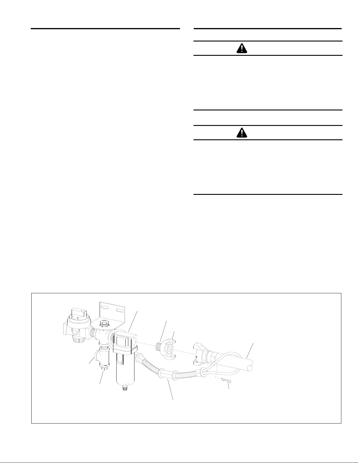
Inlet Air-Regulator Assembly ....................................... 9.4
View-Window Assembly .............................................. 9.5
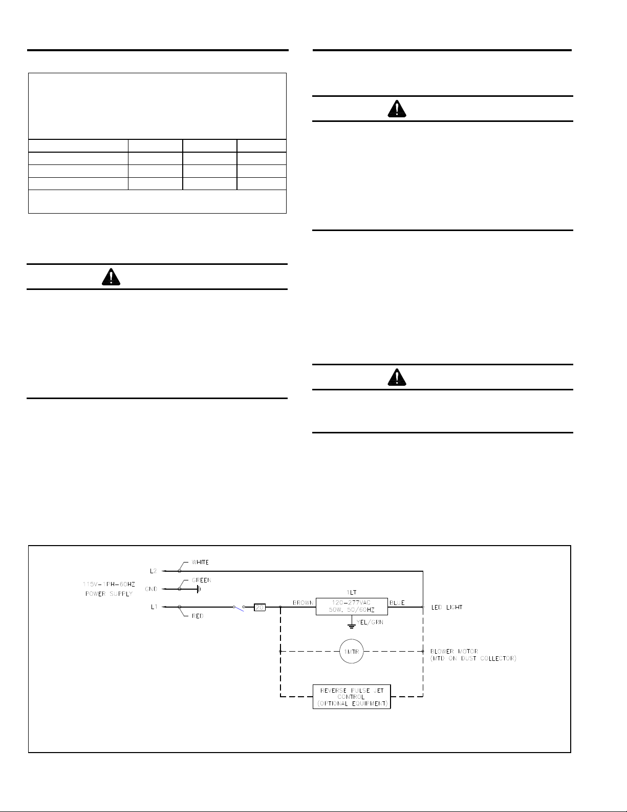
LED Light Assembly .................................................... 9.6
Foot-Pedal Assembly .................................................. 9.7
Metering Valve Assembly ............................................. 9.8
Cabinet Controls and Plumbing .................................. 9.9
Replacement Reclaimer Assemblies ........................ 9.10
300 CFM Reclaimer Replacement Parts ................... 9.11
600 CFM Modular Reclaimer Replacement Parts ..... 9.12
900 CFM Modular Reclaimer Replacement Parts ..... 9.13
1.4 General Description
1.4.1 BNP® blast cabinets enclose the blasting
environment to provide efficient blasting while
maintaining a clean surrounding work area. Production
rates are influenced by size of nozzle, compressor
output, working pressure, type and size of media, and
angle and distance of the nozzle from the blast surface.
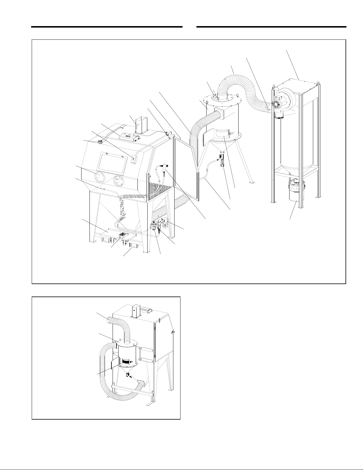
BNP suction cabinets consist of three major components:
Cabinet enclosure
Reclaimer
Dust collector
1.4.2 Cabinet enclosure: This manual covers two
BNP cabinet sizes. Each is available as a Conventional,
stand-up model and an ergonomic, sit-down model;
totaling four separate cabinet models.
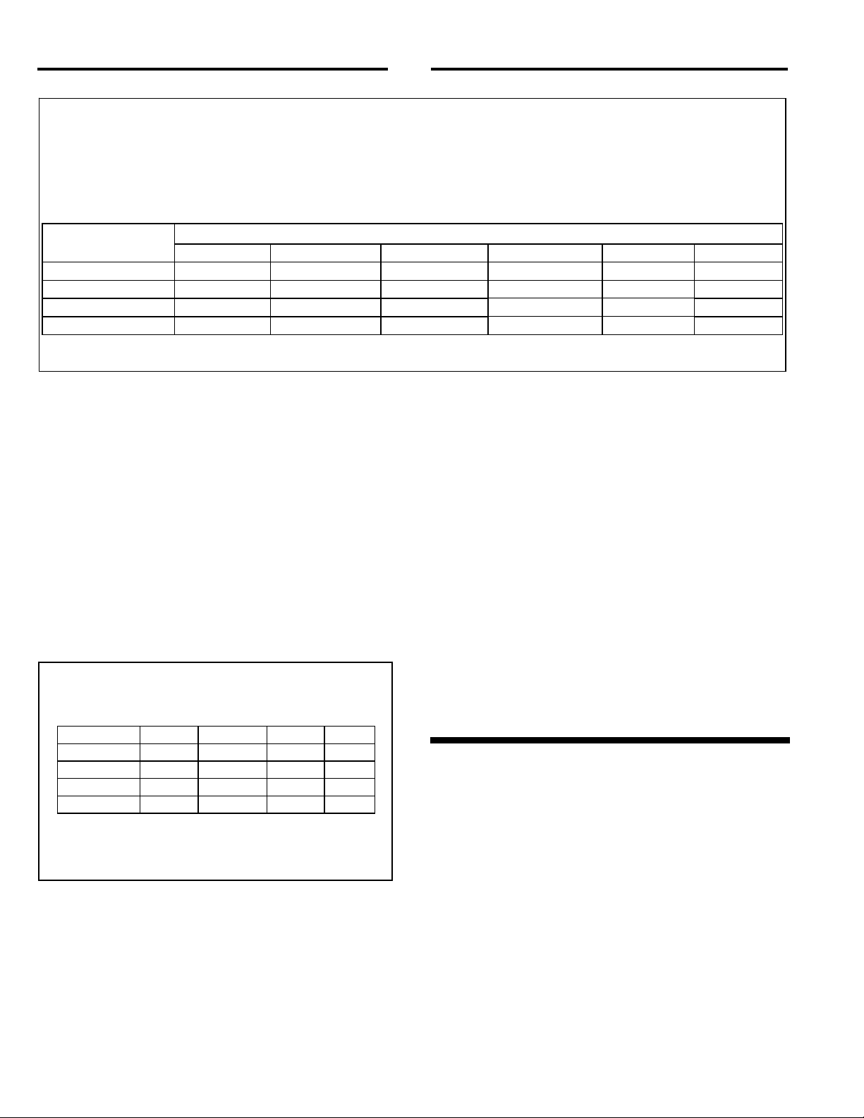
BNP-65 Approximate work chamber dimensions:
36" wide x 35" deep x 37" high.
BNP-220 Approximate work chamber dimensions:
50" wide x 39" deep x 43" high.
The extended front on ergonomic models provides
approximately 12 inches additional depth from the arm
port and above, and is approximately 3 inches narrower
than the widths shown above.
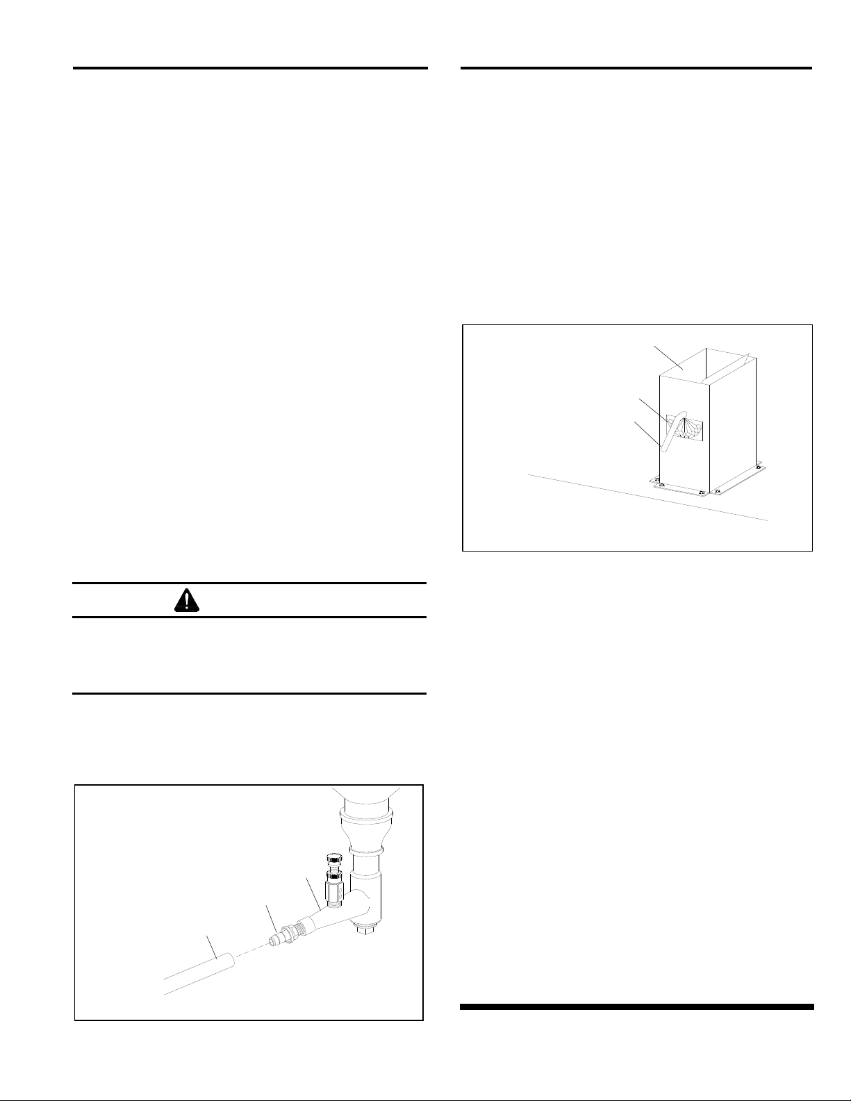
1.4.3 Refer to Figure 1 for arrangement of components
with a CDC-1 Dust Collector. The illustration shows a
freestanding 900 reclaimer; 300 and 600 reclaimers are
mounted on the back of the cabinet, as shown in Figure 2.
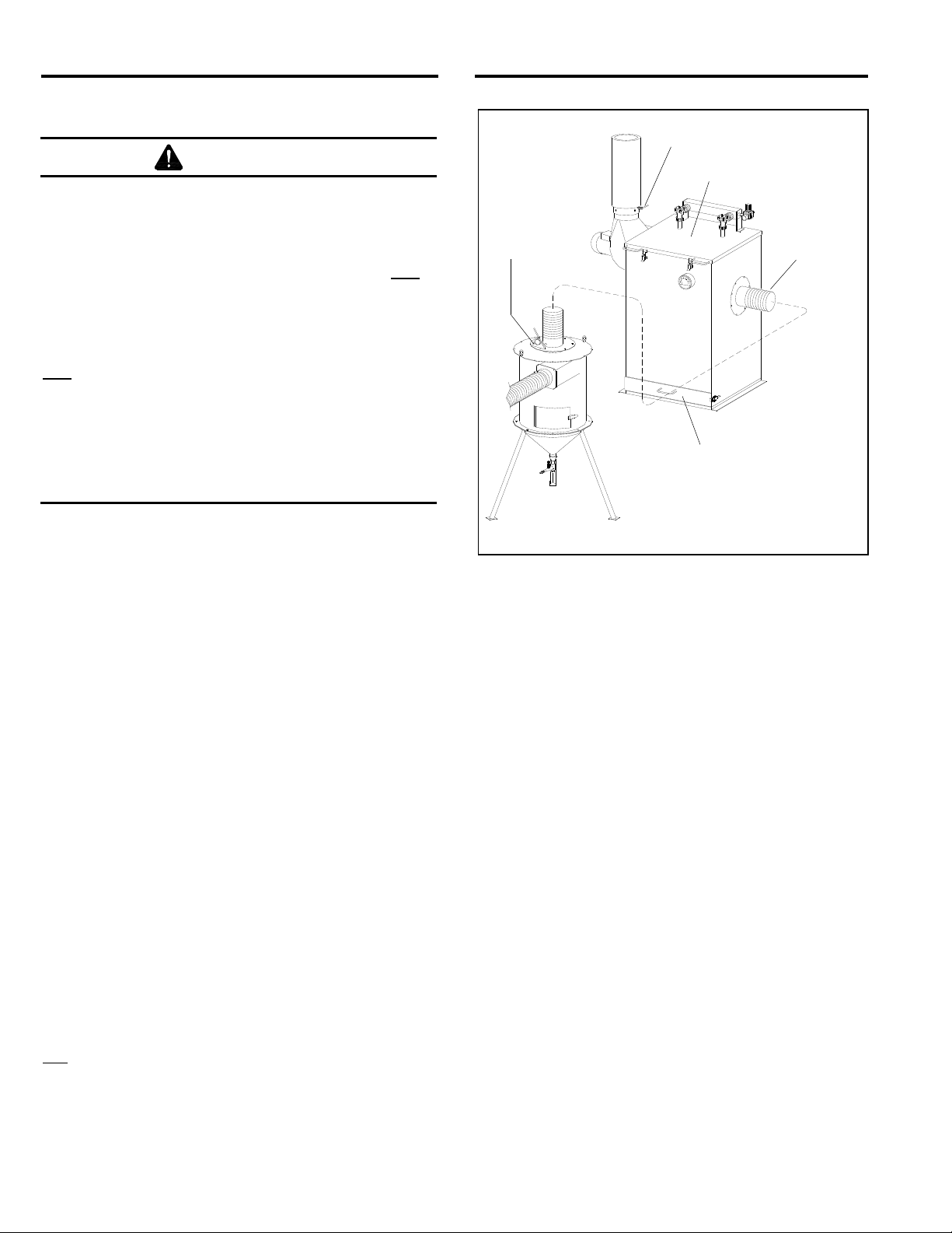
Figure 3 shows the arrangement with an RPC-2 (600 cfm or
900 cfm only) Reverse-Pulse Dust Collector with dust
drawer. The optional RPH-2 (600 cfm and 900 cfm) is set up
the same way as the RPC-2, but includes a hopper for
additional dust storage and empties into a drum. The overall
height of an RPH-2 is approximately 10.5 feet and 12 feet
when the top access door is open. To upgrade, an RPC-2
or RPH-2 Dust Collector may be added at any time.

BNP® 65 and 220 SUCTION BLAST CABINETS Page 3
© 2019 CLEMCO INDUSTRIES CORP. www.clemcoindustries.com Manual No. 21309, Rev. J 01/19
Figure 1
Figure 2
1.5 Theory of Operation
1.5.1 Once the cabinet is correctly set up and turned
on, the cabinet is then ready for operation by actuation
of the foot pedal. Fully depressing down on the foot
pedal causes air to flow through the blast gun. The
partial vacuum created by air moving through the gun
draws media into the blast-gun mixing chamber. The
media mixes with the air stream and is propelled out the
nozzle. After striking the object being blasted, the blast
media, fines, dust, and byproducts generated by blasting
fall through the grate into the cabinet hoppers. These
particles are then drawn into the reclaimer for
separation. Dust and fines are first separated from
reusable media and pass into the dust collector. Next, the
media is screened for oversize particles and returned to
the reclaimer hopper for reuse. Dust and fines entering
the dust collector are removed from the air stream as
they pass through the filters, discharging clean air.
When the foot pedal is released, blasting stops.
Cabinet shown with extended Ergo front and freestanding 900 cfm reclaimer. 300 and
600 cfm reclaimers are mounted on back of cabinet, as shown in Figure 2.
LED Light
Unlined Flex Hose
Metering Valve
Media Hose
BNP Blast Gun
Externally Adjustable Vortex
(Optional on system with CDC-1 Dust Collector)
Debris Screen
Reclaime
r
Dust-Collector Damper
Dust Drum
Air-Inlet Damper
Pilot Regulator
On-Off Switch
Auxiliary-Air Port, plugged, use for pneumatic accessories.
Blow-Off
Nozzle
Pilot-Operated Regulator
Door Interlock Valve
Door Interlock Actuato
r
Foot Pedal
Adjustable
Foot Shelf
Ergo Models Only
Fork Lift Slots
Compressed-Air Filter
Attachment for compressed-air supply.
CDC-1 Dust Collector
Light-Lined Flex Hose
Arm Ports
300 cfm and 600 cfm
reclaimers are mounted
on rear of the cabinet.
Debris Screen
To dust collector.

BNP® 65 and 220 SUCTION BLAST CABINETS Page 4
© 2019 CLEMCO INDUSTRIES CORP. www.clemcoindustries.com Manual No. 21309, Rev. J 01/19
1.6 Reverse-Pulse Dust Collector Options
WARNING
All dust is hazardous to breathe. Emissions can
occur from the dust collection system. Identify
all materials that are to be removed by blasting;
if any toxic materials such as lead dust or dust
from other heavy metals and corrosives, or any
other toxic materials are being removed, use a
HEPA afterfilter to assist in maintaining
inhalation hazards below the permissible
exposure limits (PELs). Prolonged exposure to
any dust can result in serious lung disease and
death. Short-term ingestion of toxic materials
can cause serious respiratory injury or death.
Filtration may not be adequate in reducing all
inhalation hazards. It remains the employer’s or
user’s responsibility to ensure all emissions are
safe to breathe.
1.6.1 CDC-1 Dust Collectors: Shown in Figure 1, the
collector is available in 300, 600, and 900 cfm models.
The single-filter cartridge is cleaned by using a manually
controlled pulse of compressed air. Dust collects in a 5-
gallon dust drum, which must be frequently emptied.
CDC-1 Dust Collectors are standard with BNP cabinets
unless an optional RPC-2 or RPH-2 Dust Collector is
ordered at time of purchase. Refer to manual number
28225.
1.6.2 RPC-2 Dust Collectors: Shown in Figure 3, this
collector is available in 600 cfm and 900 cfm models.
Dual-filter cartridges are automatically cleaned by a
timed, periodic pulse of compressed air. Dust collects in
the drawer, and it must be frequently emptied. Refer to
manual number 22788.
1.6.3 RPH-2 Dust Collector: The RPH-2 is available
in 600 cfm and 900 cfm models. It is set up and operate
the same as the RPC-2, as shown in Figure 3, but
instead of a dust drawer the collector sits atop a hopper,
which provides additional dust storage and empties into
a 30-gallon drum. Refer to manual number 21449.
1.6.4 HEPA (high-efficiency particulate air) Filter:
Optional HEPA afterfilters provide additional filtration
and must be used with a reverse-pulse cartridge
collector when removing toxic coatings, heavy metals, or
any other toxic materials. Refer to the applicable dust
collector manual noted in Paragraph 1.1.1 for the HEPA
option.
Figure 3
1.7 Nozzle Options
1.7.1 Unless otherwise specified at the time of
purchase, the cabinet is provided with a No. 5 (5/16"
orifice) ceramic nozzle and No. 5 (5/32" orifice) air jet.
Optional, more durable tungsten carbide and boron
carbide nozzles are available and are shown under BNP
Gun and Feed Assembly in Section 9.3. Use a boron
carbide nozzle when blasting with aggressive media, as
noted in Section 1.9.4.
1.8 Reclaimer Options
1.8.1 Replaceable rubber reclaimer liners: Rubber
liners are available for 600 cfm and 900 cfm reclaimers
that have a removable top and are designed to accept
liners. Liners are not available for 300 cfm reclaimers.
The liners prolong service life of the reclaimer and
should be installed when using silicon carbide, aluminum
oxide, or other aggressive media, as noted in Section
1.9.4. Rubber liners are shown on Page 32, Figure 35.
1.8.2 Externally adjustable vortex option: Not
available for 300 cfm reclaimer. The vortex is available
for 600 cfm and 900 cfm reclaimers. It fine-tunes media
separation; refer to Section 5.5 for additional
information. The vortex is an option when the cabinet is
provided with a CDC-1 Dust Collector but is standard on
reclaimers when the cabinet is provided from the factory
with an RPC-2 or RPH-2 Dust Collector.
Duct
Inlet
RPC-2 Dust Collector
Dust-Collector Damper
Adjustable
Vortex
Dust Drawer

BNP® 65 and 220 SUCTION BLAST CABINETS Page 5
© 2019 CLEMCO INDUSTRIES CORP. www.clemcoindustries.com Manual No. 21309, Rev. J 01/19
1.9 Blasting Media
1.9.1 Always use media specifically manufactured for
blasting and that are compatible with the surface being
blasted. Media produced for other applications may be
inconsistent in size and shape, contain particles that
could jam the media metering valve, or cause irregular
wear. Always obtain the safety data sheet (SDS) for the
blasting media prior to blasting and identify material
being removed by blasting, paying particular attention to
worker health risks and presence of any hazardous/toxic
substances.
Most common reusable media specifically manufactured
for blasting can be used in ZERO cabinets. The listing of
media sizes shown in this section and in Figure 4 are
provided as a guideline only. The guideline is based on
standard 5/32" orifice air jet with 5/16" nozzle and average
conditions with variables such as blast pressure, media-
air mixture, visibility inside the cabinet, humidity, and
reclaimer cleaning rate.
Several variables that affect the reclaimer cleaning rate
include reclaimer size (cfm), contamination of parts
being blasted, media friability, damper setting (static
pressure), and dust-collector filter loading (differential
pressure across the dust filters).
As a rule, larger orifice air jets and nozzles deliver more
media, requiring higher performance from the reclaimer.
When using larger nozzles, the maximum mesh size of
media will be smaller than normally recommended.
Using media finer than those recommended may
decrease visibility and, at some point, carry over to the
dust collector. Media coarser than those recommended
may be too dense for the reclaimer to recover from the
cabinet hopper.
1.9.2 Steel shot and steel grit: Steel shot S-170 to
S-70 or steel grit 50-mesh to 120-mesh may be used in
BNP Cabinets configured for using steel media.
Using steel media requires a smaller diameter conveying
hose (usually reduced one size from standard) and a 900
cfm or larger reclaimers. Rubber curtains should be used
to protect the cabinet walls from peening, warping, and
rapid wear. For these applications, cabinets can be
ordered with reduced-size flex hose appropriately sized
for steel grit, and with rubber curtains installed. They may
also be field installed later. NOTE: Steel grit or shot is too
heavy to use with cabinets equipped with 300 and 600
cfm reclaimers.
1.9.3 Sand and slag: Sand and slag media are not
suitable for cabinet use. Sand should NEVER be used
for abrasive blasting because of the respiratory hazards
associated with media containing free silica. Slags are
not recommended because they rapidly break down and
are not recyclable.
1.9.4 Silicon carbide, aluminum oxide, and garnet:
These are the most aggressive of the commonly used
media. Aggressive media may be used, but the service
life of any components exposed to the media will be
reduced. To avoid unscheduled downtime and maximize
cabinet life, periodically inspect the reclaimer wear plate,
blast hose, and nozzle for wear and replace parts as
needed.
When using aggressive media only occasionally, install
an optional aluminum oxide kit, which includes rubber
curtains for the cabinet interior and a boron carbide-lined
nozzle. When using aggressive media on a regular
basis, install the aluminum oxide kit and a fully rubber-
lined reclaimer. Rubber-lined reclaimers are available as
factory-installed items, or field-installed liners can be
installed later on 600 cfm and 900 cfm reclaimers if they
have removable tops and are designed to accept liners.
Nozzles lined with boron carbide extend nozzle wear life.
Refer to Section 9.3: BNP Gun and Feed Assembly.
1.9.5 Glass bead: Most beads are treated to ensure
free-flow operation, even in environments of moderately
high humidity. Glass beads subjected to excessive
moisture may be reused only after thoroughly drying and
breaking up of any clumps.
1.9.6 Lightweight and fine-mesh media: When
using lightweight (such as agricultural) media or fine-
mesh (180-mesh and finer) media, the reclaimer inlet
baffle may need to be removed to retain media and
avoid carryover. On 600 cfm and 900 cfm reclaimer
models with bolt-on removable tops, baffle removal and
replacement is easily accomplished, as explained in
Section 7.10. Reclaimers with welded-on tops require
grinding to remove the baffle, and once it is removed it
cannot be replaced.
1.9.7 Plastic media: Plastic and similar lightweight
and/or nonaggressive media are generally not
recommended for suction-style cabinets because the
lower blast velocity of suction blasting combined with the
softer and lighter weight media do not provide the media
impact for productive blasting. Best performance from
plastic media is achieved with pressure blasting,
requiring a pressure vessel with a 60-degree conical
bottom. Refer to Clemco’s Aerolyte cabinet line.
1.9.8 Bicarbonate of soda: Bicarbonate of soda is
not recommended for use in standard cabinets. Bicarb is
a one-use media, which will quickly saturate the filter
cartridge(s). Best performance from bicarb media is
achieved with pressure blasting, requiring a pressure
vessel. Refer to Clemco’s Aerolyte cabinet line for
cabinets that are specifically designed for use with
bicarbonate of soda.

BNP® 65 and 220 SUCTION BLAST CABINETS Page 6
This guideline to media type and selection is based on standard 5/32" orifice air jet with 5/16" nozzle and average
conditions, such as air pressure, media-air mixture, visibility, contamination of parts being cleaned, humidity, media
friability, reclaimer cleaning rate, etc. As a rule, larger nozzles deliver more media, requiring higher performance from
the reclaimer. Larger air jets and nozzles decrease the maximum mesh size of media from those recommended.
Media that is finer than those recommended may decrease visibility and increase carry over to the dust collector.
Media coarser than those recommended may be too dense for the reclaimer to recover from the cabinet hopper.
MEDIA TYPE
RECLAIMER SIZE STEEL GRIT STEEL SHOT GLASS BEAD ALUM. OXIDE FINE MESH LIGHT WT.
*300 cfm w/4" inlet Do not use Do not use No. 6 to No. 12 60 to 180-mesh See 1.9.6 See 1.9.7
*600 cfm w/5" inlet Do not use Do not use No. 6 to No. 12 54 to 180-mesh See 1.9.6 See 1.9.7
900 cfm w/5" inlet 50 to 120 S-170 to S-70 No. 4 to No. 8 24 to 100-mesh Do not use Do not use
*900 cfm w/6" inlet Do not use Do not use No. 5 to No. 12 30 to 180-mesh See 1.9.6 See 1.9.7
* Standard reclaimer inlets
Figure 4
1.10 Compressed-Air Requirements
1.10.1 The size of the compressor required to operate
the cabinet depends on the size of the air jet and
blasting pressure. Unless otherwise specified, cabinets
are supplied with a No. 5 (5/32" orifice) jet. Refer to the
table in Figure 5 to determine air consumption. Consult
with a compressor supplier for suggested compressor
size based on the air consumption. NOTE: A separate
air line is required for the reverse-pulse dust
collector. If preferred, remove the plug from the
auxiliary air port (shown in Figure 6) and connect a
1/4″ ID or larger air line to the dust collector pulse
reservoir/manifold. Refer to the dust-collector
owners manual.
Compressed-Air Consumption in CFM
BNP Gun
Jet
Orifice
Nozzle
Orifice
CFM
PSI
No. 4 1/8" 5/16" 21 80
No. 5 5/32" 5/16" 32 80
No. 6 3/16" 3/8" 47 80
*No. 7 7/32" 7/16" 62 80
*No. 8 1/4" 1/2" 86 80
* Using this combination could affect usable
media size; refer to Section 1.9.
Figure 5
1.10.2 The air filter at the air-inlet connection reduces
condensed water from the compressed air. Its use is
especially important in areas of high humidity or when
using fine-mesh media. Moisture causes media to clump
and inhibits free flow through the feed assembly. If the
filter does not remove enough moisture to keep media
dry and flowing, it may be necessary to install an air
dryer or aftercooler in the air-supply line.
1.11 Electrical Requirements
All wiring external of the cabinet is provided by the user
to comply with local electrical codes.
1.11.1 Electrical requirements depend on the size and
phase of the dust-collector exhauster motor. NOTE: Full-
load amps (FLA) shown below are for the motor only;
the lights draw less than one amp. Standard cabinets
are supplied as follows:
300 cfm: 1/2 HP, 120/208/230V, 1 PH, 60 HZ
120, FLA 120/7, 208/3.4, 230/3.5.
600 cfm: 1 HP, 120/230V, 1 PH, 60 HZ
120, FLA 120/12, 208/6.6, 230/6.2.
900 cfm: 2 HP, 208/230/460V, 3 PH, 60 HZ
Supplied with 230-volt control panel unless 460-volt is
specified at the time the order is placed.
FLA 208/5.5, 230/5.6, 460/2.8.
Refer to Section 2.5 to connect electrical service.
2.0 INSTALLATION
Unless noted otherwise, the sequence of assembly in
Sections 2.2 through 2.8 may be done in any order that
is convenient for the installer.
2.1 General Installation Notes
2.1.1 Refer to Figures 1 and Figure 2 (and Figure 3
for optional RPC-2 Dust Collector) for the general
arrangement. Place all components in a convenient
location where compressed air and electrical service are
available. The cabinet location must comply with OSHA
and local safety codes. Allow for full access to all doors
and service areas, and for efficient handling of large
parts. Provide enough clearance at the dust collector for
maintenance and to remove the dust container. Place

BNP® 65 and 220 SUCTION BLAST CABINETS Page 7
© 2019 CLEMCO INDUSTRIES CORP. www.clemcoindustries.com Manual No. 21309, Rev. J 01/19
freestanding reclaimers directly behind the cabinet with
flex-hose connections and metering valve facing toward
the cabinet to allow for as few bends as possible to
prevent wear. Determine the best location for all
components and position them before making
compressed air connections, electrical connections, and
attaching flex hose.
2.1.2 Refer to the dust-collector owner’s manual to set
up the dust collector and prepare it for operation.
2.2 Connect Conveying (flex) Hose
2.2.1 Connect the smaller-diameter flex hose between
the cabinet-hopper pipe adaptor and reclaimer inlet
adaptor, and connect the larger-diameter hose between
the reclaimer outlet and dust collector inlet. It is easier to
slip the hose over the adaptors and create a tighter seal if
the first two or three inches of wire are removed from the
inside of the hose. Use care not to damage the hose.
Clamp flex hose securely in position with worm clamps
provided. NOTE: The hose wire helps dissipate static
electricity in the conveying hose and also helps
ground each segment. In order for the hose wire to
dissipate static electricity, the wire must touch the
metal of each segment.
2.3 Connect Compressed-Air-Supply Lines
A separate air line is required for the dust collector
pulse. Refer to the dust-collector owner’s manual. The
line may be connected to the auxiliary-air port on the
cabinet plumbing, as shown in Figure 6.
WARNING
Failure to observe the following before
connecting the equipment to the compressed-
air source can cause serious injury from the
sudden release of trapped compressed air:
Lockout and tagout the compressed-air
supply.
Bleed the compressed-air supply line.
WARNING
To avoid the risk of injury from compressed air,
install an isolation valve and bleed-off valve
where the air supply is tapped into the
compressed-air system. This enables a lockout
and tagout procedure and depressurization of
the compressed-air line before performing
maintenance.
2.3.1 Refer to Paragraph 2.3.2 to determine the
recommended air-supply hose size, then refer to Figure
6 and apply thread sealant to the male threads of an
air
fitting that is compatible with the air-supply hose
fitting, and install it onto the 1/2-NPT air filter located
under the cabinet hopper. The style of connection shown
in Figure 6 is for reference only.
2.3.2 Refer to the table in Figure 7 to determine the
minimum ID air-supply line to the cabinet air inlet. A
smaller diameter hose may reduce blasting efficiency.
Figure 6
1/2" NPT Air
Use safety lock pins to secure twist-on couplings.
Air-Supply Hose
Air Fitting
Use safety cable to prevent separated hose from whipping.
Once installed, all slack must be removed from the cable.
Plugged Auxiliary-Air Port
A
pp
l
y
thread sealant to male threads.
To Blow-off Nozzle
Some items removed for clarity.

BNP® 65 and 220 SUCTION BLAST CABINETS Page 8
© 2019 CLEMCO INDUSTRIES CORP. www.clemcoindustries.com Manual No. 21309, Rev. J 01/19
MINIMUM COMPRESSED-AIR LINE ID
Jet Size
Air Line Length
1/8"
No. 4
5/32"
No. 5
3/16"
No. 6
25 feet 3/4" 3/4" 1"
50 feet 3/4" 3/4" 1"
75 feet 3/4" 1" 1"
100 feet 3/4" 1" 1"
Figure 7
2.3.3 Connect the air line from the air source to the
air-filter inlet.
WARNING
Hose disconnection while under pressure can
cause serious injury or death. Use safety lock
pins or safety wire to lock twist-on couplings
together and prevent accidental separation, and
also use safety cables to prevent hose from
whipping should separation occur. Safety lock
pins and safety cables are listed in Section 9.1:
Optional Accessories.
2.3.4 Refer to the dust-collector owner’s manual and
connect a compressed-air line to the pulse manifold.
2.4 Ground the Cabinet and Dust Collector
2.4.1 To prevent static electricity buildup, attach an
external grounded wire from an earth ground to the
grounding lug on the left rear of the cabinet. Refer to the
dust-collector owner’s manual and connect a ground
wire to the dust collector.
2.5 Connect Electrical Service
WARNING
Shorting electrical components can result in
serious injury or death from electrical shock or
equipment damage. Electrical power must be
locked out and tagged out before performing
any electrical work. All electrical work or any
work done inside a control panel or junction
box must be performed by a qualified
electrician and comply with applicable codes.
All wiring external of the cabinet is provided by the user
to comply with local electrical codes.
2.5.1 Single-phase wiring
2.5.1.1 Standard 300 cfm and 600 cfm cabinets and
dust collectors are 120-volt single-phase. Power to the
cabinet is supplied by a U-ground plug; plug it into a
120-volt outlet.
WARNING
Do not use electrical adaptors that eliminate the
ground prong on 120-volt plugs. Doing so can
cause electric shock and equipment damage.
2.5.1.2 Refer to the wiring schematic in Figure 8 and
wire the dust collector motor, per instruction on the
motor data plate to the junction box mounted on the
cabinet. When wired as noted, the dust-collector
exhauster motor will start when the cabinet light switch is
turned ON and stop when the switch is turned OFF.
Figure 8
115 VOLT, 1PH WIRING FOR CABINET AND DUST-COLLECTOR MOTOR
Dashed lines indicate wiring by others (not
Clemco). Wiring is to be of color and gauge
shown, and marked on each end with the
wire number or terminal number as shown.

BNP® 65 and 220 SUCTION BLAST CABINETS Page 9
© 2019 CLEMCO INDUSTRIES CORP. www.clemcoindustries.com Manual No. 21309, Rev. J 01/19
2.5.2 Three-phase wiring
A wiring schematic is packed inside the cabinet’s control
panel. After wiring is completed, keep a copy of the
schematic with the manual for future reference and for
electrical replacement parts.
2.5.2.1 Refer to the wiring schematic stowed inside the
control panel mounted on the cabinet and wire from the
users disconnect to the panel and from the panel to the
dust collector motor, per instruction on the motor data
plate.
2.5.2.2 Check the amperage on initial startup; if the
motor draws excessive amperage, gradually close the
dust-collector damper, located on the inlet on CDC Dust
Collectors and on the exhauster outlet on RPC-2 and
RPH-2 Dust Collectors, until the amperage is within the
specifications shown on the motor plate.
2.5.2.3 After wiring is completed, observe the warning
below and check the motor rotation. To check rotation,
turn the On-Off switch ON and quickly turn it OFF, causing
the motor to rotate slowly. Look through the slots in the
motor fan housing where rotation of the fan can easily be
observed. Proper rotation is indicated by the arrow on the
exhauster housing; the fan should rotate toward the
exhauster outlet. To reverse rotation, change the wires as
noted on the motor plate.
WARNING
Do not look into the exhauster outlet while the
paddle wheel is turning. Injury to the eye or face
can occur from objects being ejected from the
exhauster.
2.6 Connect Media Hose to Metering Valve
900 cfm freestanding reclaimer only. Hoses are already
attached to 300 and 600 cfm reclaimers.
Figure 9
2.6.1 Refer to Figure 9 and attach the clear media
hose from under the cabinet hopper to the metering
valve at the bottom of the reclaimer hopper by sliding the
hose onto the barded fitting on the metering valve.
2.7 Set Air-Inlet Damper ‒ Figure 10
2.7.1 The air-inlet damper is located on the top of the
cabinet and must be set to match the cabinet
dimensions and reclaimer size. The air damper was
preset prior to shipment; confirm the initial setting as
noted in Paragraph 2.7.2.
Figure 10
2.7.2 The label on the damper shows the settings in
degrees. The initial setting should align the handle as
follows:
65 with 300 reclaimer .... align handle to 30 degrees
65 with 600 reclaimer .... align handle to 30 degrees
65 with 900 reclaimer .. align to 0 degree (full open)
220 with 600 reclaimer .... align handle to 30 degrees
220 with 900 reclaimer .. align to 0 degree (full open)
2.7.3 Loosen the lock nuts and align the damper
handle as noted. When correctly positioned, tighten the
lock nuts to maintain the setting. Refer to Section 5.6 for
adjustment procedure.
2.8 Final Assembly
2.8.1 Position the foot pedal on the floor at the front of
the cabinet or on the foot shelf on ergonomic models.
2.8.2 A package of five view-window cover lenses is
supplied with the cabinet. To install a cover lens, remove
the adhesive backing and apply the lens to the clean, dry,
inner surface of the view window. Refer to Section 7.3.
When the cover lens becomes pitted or frosted, replace it.
Barbed Hose Fitting
Clear Media Hose
Metering Valve
Damper Handle
Degrees Label
Align handle to degrees, as
noted in Paragraph 2.7.2.
Air-Inlet Damper

BNP® 65 and 220 SUCTION BLAST CABINETS Page 10
© 2019 CLEMCO INDUSTRIES CORP. www.clemcoindustries.com Manual No. 21309, Rev. J 01/19
3.0 FIELD INSTALLED ACCESSORIES
Optional accessories are shown in Section 9.1
3.1 Aluminum Oxide (aggressive media) Kit
3.1.1 An optional aluminum oxide kit is available
factory installed or may be field installed later.
Factory-installed kits consist of black-rubber cabinet
curtains with grommets, curtain hardware, and a boron
carbide nozzle.
Field-installed (or replacement factory-installed) kits
consist of black-rubber cabinet curtains (refer to Section
3.2 for curtain installation), a boron carbide nozzle, and
light-lined flex hose. If the existing flex hose is in good
condition, reserve the new hose for future replacement.
3.2 Cabinet Curtains Installation
3.2.1 Match curtains to corresponding wall and doors.
3.2.2 Front and rear walls: Position the curtains on
the wall to be protected. Use the curtains as templates
to mark each mounting point through the grommet holes
along the upper edge of the curtain. NOTE: When laying
out the attachment points, the upper edge of the rear
curtain should be below the bottom edge of the air-duct
partition. Remove the curtains and drill a .187" (3/16")
diameter hole at each point marked. Install the curtains
using the fasteners provided (machine screw, 11/16" OD
flat washer, lock washer, and nut) at each grommet. The
flat washer is used between the screw head and the
rubber-curtain grommet on all curtains.
3.2.3 Doors: Using protectors against the curtains
and outer doors; clamp the door curtains in place.
NOTE: When laying out the attachment points, the upper
edges of the door curtains should be even with the outer
edges of the door’s soundproofing panel. Insert a #10
self-drilling screw with an 11/16 OD flat washer through
the grommet holes. Use a screw gun with a 5/16" socket
to drill and thread the screws through the door’s inner
wall at each grommet.
3.2.4 Ergo side extensions: Position the curtain on
the wall to be protected. Use the curtain as a template
and mark the top mounting point through the grommet.
Remove the curtain and drill a .187" (3/16") diameter
hole at each point marked. Install the curtains using the
fasteners provided (machine screw, 11/16 OD flat
washer, lock washer and nut) at each grommet. The flat
washer is used between the screw head and the rubber-
curtain grommet on all curtains. After the curtain is hung,
mark and drill the cabinet and attach the lower
grommets in like manner.
3.3 Manometer
The optional manometer kit is listed in Section 9.1.
3.3.1 Consistent static pressure is necessary for
precise media separation, as the reclaimer's efficiency is
achieved by a centrifugal balance of air flow, particle
weight, and size. The manometer measures static
pressure. Reclaimer static pressure is set by adjusting
the dust collector-damper. Refer to Section 5.4 to adjust
static pressure. Refer to Section 5.8 for instructions on
using the manometer.
3.4 Armrest
3.4.1 Assemble the armrest and mounting brackets,
as shown in Figure 11.
3.4.2 Position the assembly so the armrest is about
even with the bottom of the arm port opening. Mark one
hole location on the front of the cabinet at each
mounting bracket.
Figure 11
3.4.3 Drill a 3/8" hole at both locations and mount the
armrest using 5/16 cap screw, washers, and nuts. Install
the bolts from inside the cabinet to protect the threads
from abrasion, should the armrest need to be removed
at a later date.
3.4.4 Match drill the remaining four bracket holes and
install the remaining fasteners.
3.4.5 Loosen the fasteners on the slotted bracket and
raise or lower the armrest to a comfortable position.
3.5 Turntable with Workcar and Track
3.5.1 Components of the turntable and track assembly
are shown in Figure 12. The assembly consists of:
The inside track assembly, which is placed inside
the cabinet.
The hinged track extension attaches to the support
table and swings up to clear the door.
5/16 x 1" Cap Screw,
Flat Washer, Lock
Washer, and Nut
Armrest
3/8 x 1" Cap Screw
and Lock Washer

BNP® 65 and 220 SUCTION BLAST CABINETS Page 11
© 2019 CLEMCO INDUSTRIES CORP. www.clemcoindustries.com Manual No. 21309, Rev. J 01/19
Track support table.
Turntable and workcar assembly.
Figure 12
NOTE: The track may be placed on either side of the
cabinet, allowing entry through either the right side or left
side door; the right side is shown in the illustrations.
When installing the inside track, place it so the stops,
shown in Figure 13, are opposite the entry door.
3.5.2 Place the inside track in the cabinet over the
existing grate, as shown in Figure 13.
Figure 13
3.5.3 Position the track support table and extension,
as shown in Figure 14. When the hinged extension is
lowered, the extension tracks must rest on the angled
locating supports welded to the bottom of the inside
tracks, and it must butt against the inside tracks.
3.5.4 Loosen the leveling-pad lock nuts and raise or
lower the pads, as needed to adjust the height of the
table, to make sure that the inside and outside tracks are
aligned, that the hinged extension rest evenly on the
support angles when the extension is lowered, and that
the table is level.
3.5.5 Raise the track extension, and then open and
close the door to make sure they function correctly.
When certain the table and tracks are aligned and level,
and that the workcar moves smoothly on all tracks,
tighten the leveling-pad lock nuts and anchor the support
table to the floor through the holes in the leveling pads.
Figure 14
3.6 Optional Externally Adjustable Vortex Cylinder
Not available for 300 cfm reclaimer.
3.6.1 The externally adjustable vortex is an option
when the cabinet is provided with a CDC-1 Dust
Collector. The vortex is standard with 600 cfm and 900
cfm reclaimers when the cabinet is provided from the
factory with an RPC-2 or RPH-2 Dust Collector.
4.0 OPERATION
NOTICE
Do not pulse new dust collectors or
replacement cartridges until the cartridges are
properly seasoned, as instructed in the dust-
collector owner’s manual. Pulsing unseasoned
cartridges can decrease the efficiency of dust
collectors and cause premature cartridge failure.
4.1 Media Loading
4.1.1 Media capacity: The approximate capacity and
minimum media amount is shown in the table below.
Reclaimer Size Minimum Wt. Capacity
300 cfm 10 lbs 50 lbs. (0.5 cuft)
600 cfm 20 lbs 75 lbs. (0.75 cuft)
900 cfm 30 lbs 100 lbs. (1 cuft)
Inside Track
Hinged Track Extension
Track Support Table
Turntable and Workcar
Stops
Entry Door
The hinged extension
must rest on the
inside-track support
angles when lowered.
Support Angles
Grate
Anchor Holes (4 places)
Leveling Pads (4)

BNP® 65 and 220 SUCTION BLAST CABINETS Page 12
© 2019 CLEMCO INDUSTRIES CORP. www.clemcoindustries.com Manual No. 21309, Rev. J 01/19
4.1.2 Media loading: With the exhauster OFF, add
clean, dry media by pouring it through the reclaimer
door. Do not fill above the hopper on the reclaimer. Do
not pour media directly into the cabinet hopper, as
overfilling may occur. Overfilling will result in media
carryover to the dust collector and possible blockage in
the conveying hose. Refill only after all media has been
recovered from the cabinet.
4.2 Media Unloading ‒ Figure 15
4.2.1 To empty the cabinet of media, turn ON the
exhauster and blow off the cabinet interior until all media
is recovered from the cabinet. Turn OFF the exhauster
and place an empty bucket or other suitable container
under the metering valve. Unscrew the plastic plug from
the metering valve, permitting media to flow into the
bucket. If media doesn't flow, it has caked; open the fill
door and stir media until it starts to flow. Before the
container becomes too heavy to easily handle, replace the
plug and empty the container. Replace the plug when the
reclaimer is empty or purge the hose(s), as noted below.
4.2.2 To purge the media hose, before replacing the
plug turn ON the exhauster, grasp the gun, and press
the foot pedal using the gun to blow off the cabinet
interior until the air from the gun and the cabinet are
clear. Turn OFF the exhauster and replace the plug.
Figure 15
4.3 Loading and Unloading Parts
WARNING
Use solid fixturing to hold heavy parts in place.
Do not remove lift equipment until the part is
adequately supported to prevent movement.
Moving heavy, unsupported parts may cause
them to shift or topple and cause severe injury.
This is especially important with the use of
turntables.
4.3.1 Load and unload parts through either door.
4.3.2 Parts must be free of oil, water, grease, or other
contaminants that will clump media or clog filters.
4.3.3 When blasting small parts or objects having small
pieces that could become dislodged and fall off, place an
appropriately sized screen over the grate (or under the
grate when frequently blasting small parts) to prevent
parts from falling into the hopper. If an object should fall
through the grate, stop blasting immediately and
retrieve it.
4.3.4 Close door; the door interlock system will
prevent blasting if either door is open.
4.4 Blasting Operation
W
ARNING
To avoid the inhalation of dust, which can
cause respiratory illness from short-term
ingestion or death from long-term ingestion:
Use the blow-off nozzle to blow media off
parts before opening doors.
After blasting, keep doors closed and
exhauster running until the cabinet is clear
of all airborne dust.
Always close cabinet, reclaimer, and dust-
collector doors before blasting. Keep all
doors closed during blasting.
Always wear blast gloves.
Stop blasting immediately if dust leaks are
detected.
4.4.1 Slowly open the air supply to the cabinet. Check
for air leaks on the initial startup and periodically
thereafter.
4.4.2 Turn ON the lights and exhauster. The ON/OFF
switch performs both functions.
4.4.3 Load parts.
4.4.4 Close door; the door interlock system will
prevent blasting if either door is open.
4.4.5 Adjust the pilot-pressure regulator to the
required blast pressure, per Section 5.1. The regulator is
located on the top-left side of the cabinet.
4.4.6 Insert hands into rubber gloves.
Reclaimer Hopper
Metering Valve
Plastic Plug
Unscrew plug to empty
media from reclaimer.

BNP® 65 and 220 SUCTION BLAST CABINETS Page 13
© 2019 CLEMCO INDUSTRIES CORP. www.clemcoindustries.com Manual No. 21309, Rev. J 01/19
4.4.7 To blast, hold the gun firmly, point the gun
toward the object to be blasted, and apply foot pressure to
the top of the foot pedal; blasting will begin immediately.
WARNING
Shut down the cabinet immediately if dust leaks
are detected from the dust collector or cabinet.
Make sure the dust-collector filter(s) are
correctly seated and not worn or damaged.
Prolonged breathing of any dust can result in
serious lung disease or death. Short-term
ingestion of toxic dust, such as lead, poses an
immediate danger to health. Toxicity and health
risks vary with type of media and dust
generated by blasting. Identify all material being
removed by blasting and obtain a safety data
sheet (SDS) for the blast media.
NOTICE
To prevent rapid frosting of the view window,
avoid pointing the blast nozzle toward the
window and install a view-window cover lens,
per Section 7.3.
4.4.8 When holding parts off the grate, use a solid
conductive backrest to support the part. Without this
assist, especially with longer blasting operations, the
operator will tire easily from resisting blast pressure, and
static electricity could build up in the ungrounded part
and cause static shocks. Whenever possible, avoid
holding small parts that require blasting into the glove.
4.4.9 If an object should fall through the grate, stop
blasting immediately and retrieve it.
4.5 Blasting Technique
4.5.1 Blasting technique is similar to spray painting
technique. Smooth, continuous strokes are most
effective. The distance from the part affects size of blast
pattern. Under normal conditions, hold the nozzle
approximately 3" to 6" from the surface of the part.
4.6 Stop Blasting
4.6.1 To stop blasting, remove foot pressure from the
top of the foot pedal.
4.6.2 Use the blow-off nozzle to blow media off
cleaned parts.
4.6.3 Keep doors closed and exhauster running until
the cabinet is clear of all airborne dust.
4.6.4 Unload parts.
4.7 Shutdown
4.7.1 Shut off the air-supply valve, bleed the air-
supply line, and drain the compressed-air filter and dust-
collector pulse reservoir.
4.7.2 Switch OFF the lights and exhauster.
5.0 ADJUSTMENTS
5.1 Blasting Pressure (pilot regulator)
5.1.1 The pilot regulator (located on the top-left side of
the cabinet), enables the user to adjust blasting pressure
while blasting to suit the application. The suitable pressure
for most purposes is about 80 psi. Lower pressures may
be required on delicate substrates and will reduce media
breakdown. Higher pressure may be required for difficult
blasting jobs on durable substrates, but will increase
media breakdown. If pressure is too high, suction in media
hose will decrease, and if high enough, cause blowback in
the hose. Optimal production can only be achieved when
pressure is carefully monitored.
Figure 16
5.1.2 To adjust pressure, unlock the knob by pulling it
out, as shown in Figure 16, and turn it clockwise to
increase pressure or counterclockwise to decrease
pressure. Pressure may drop slightly from closed-line
pressure when blasting starts. Once operating pressure
is set, push the knob in to lock it to maintain the setting.
When viewed from the knob end,
turn clockwise to increase pressure;
turn counterclockwise to decrease pressure.
Adjustment Knob
Blast Pressure Regulator
Located on top-left
side of cabinet.
Push knob in to lock it.
Pull knob out to unlock
and adjust pressure.

BNP® 65 and 220 SUCTION BLAST CABINETS Page 14
© 2019 CLEMCO INDUSTRIES CORP. www.clemcoindustries.com Manual No. 21309, Rev. J 01/19
5.2 Air Jet Adjustment ‒ Figure 17
5.2.1 Thread the air jet 4-1/2 to 5 full turns into the
gun body. Doing so will leave 3-1/2 to 4 threads exposed
past the lock nut. Tighten the lock nut to maintain the
setting. Refer to Section 9.3 for optional adjusting tool,
which correctly positions the jet. Instructions are
provided with the tool.
Figure 17
5.3 Media-Air Mixture (media flow) ‒ Figure 18
5.3.1 Check the media stream for correct media-air
mixture; media flow should be smooth and appear as a
light mist coming from the nozzle.
5.3.2 If media does not flow smoothly, loosen the
locking nut and adjust the metering screw until the upper
holes in the metering stem are closed off and the lower
holes are fully open, as shown in Figure 18. This
adjustment is a starting point.
Figure 18
5.3.3 If pulsation occurs in the media hose, either
media is damp and caked, or not enough air is entering
the media stream. While blasting, loosen the locking nut
and slowly turn the adjusting screw out
(counterclockwise when viewed from the top) until media
flows smoothly. Tighten the locking nut finger-tight to
maintain the setting.
5.3.4 If media flow is too light, decrease air in the
mixture by turning the metering screw in (clockwise
when viewed from the top), covering more of the holes
so less air enters the media hose. Tighten the locking
nut finger-tight to maintain the setting.
5.4 Reclaimer Static Pressure (dust-collector
outlet damper)
5.4.1 Correct static pressure varies with size of
reclaimer, and the size, weight, and type of media.
5.4.2 Adjust static pressure by opening (handle in-line
with air flow) or closing (handle perpendicular to air flow)
the dust-collector damper. Refer to the dust-collector
owner’s manual; the damper is located on the inlet on
CDC-1 Dust Collectors and on the exhauster outlet on
RPC-2 and RPH2Dust Collectors. If the damper is not
opened far enough, the reclaimer will not remove fines,
resulting in dusty media and poor visibility, and possible
media blockage in the conveying hose. If the damper is
opened too far, it may cause carryover (usable media
carried into the dust collector) and result in excessive
media consumption. Open only as far as necessary to
obtain a balance of dust removal without media
carryover.
5.4.3 A manometer is useful when adjusting or
monitoring static pressure. The manometer kit is listed in
Section 9.1: Optional Accessories. Refer to Section 5.8
for manometer operation. The following are static-
pressure starting points for given media. Static pressure
may need to be lower with finer media, higher with
coarser media. Run the media through several blast
cycles, allowing the reclaimer to function with these
settings. Inspect the media in the reclaimer and fines in
the dust collector, as noted in Paragraph 5.4.2. Continue
adjusting static pressure until optimum dust and fines
removal without carryover is attained.
Glass Bead No. 4 to 7 .................................... 3" – 3-1/2"
Glass Bead No. 8 to 13 ................................... 2-1/2" – 3"
Aluminum Oxide, 60-mesh & coarser ................... 4" – 5"
Aluminum Oxide, 80-mesh & finer .................. 2-1/2" – 3"
*Steel Grit, 50-mesh to 120-mesh ......................... 6" – 7"
*Steel Shot S-170 to S-70 ..................................... 6" – 7"
*Refer to Section 1.9 for media limitations.
5.4.4 If the damper has been adjusted and carryover
or excessive dust in the media continues, the optional
externally adjustable vortex cylinder, available for 600
and 900 reclaimers, may help by fine tuning media
separation. The vortex cylinder is usually required only
when using 180-mesh and finer media, or lightweight
media. Refer to Section 5.5.
Adjusting Screw
Lower holes fully open.
Locking Nut
Upper holes
fully closed.
Lock Nut
Air Jet
3-1/2 to 4 threads between
lock nut and air jet hex.

BNP® 65 and 220 SUCTION BLAST CABINETS Page 15
© 2019 CLEMCO INDUSTRIES CORP. www.clemcoindustries.com Manual No. 21309, Rev. J 01/19
5.5 Optional Externally Adjustable Vortex
Cylinder – Figure 19
Not available for 300 cfm reclaimer.
The externally adjustable vortex is an option when the
cabinet is provided with a CDC-1 Dust Collector. The
vortex is standard with 600 cfm and 900 cfm reclaimers
when the cabinet is provided from the factory with an
RPC-2 or RPH-2 Dust Collector.
The vortex cylinder fine-tunes media separation. Before
adjusting the cylinder, adjust the damper on the dust
collector to increase or decrease static pressure, per
Section 5.4. Once the damper is adjusted, adjust the
cylinder.
5.5.1 The vortex cylinder is located atop the reclaimer
where the flex hose connects. Adjustments are made by
loosening the handle's tensioning knob and moving the
handle to achieve the correct setting. When the correct
setting is established, tighten the locking knob to prevent
movement. Start with the lever slightly to the right (about
1 o’clock, as shown in Figure 19) of the vertical position.
5.5.2 To remove more fines: (Too much dust in
media. Raise the cylinder by moving the lever left toward
COARSE in 1/4" increments at the indicator plate. Allow
the media to go through several blast cycles before
determining if further adjustment is needed.
5.5.3 To remove fewer fines: (Excessive usable
media is carried to the dust collector). Lower the cylinder
by moving the lever right toward FINE in 1/4" increments
at the indicator plate. NOTE: If the cylinder is lowered
too far, the reclaimer will again begin to allow usable
media to be carried over and causes abnormally high
static pressure.
Figure 19
5.5.4 When using media finer than 180-mesh, the inlet
baffle in the reclaimer may need to be removed. Refer to
Section 1.9.6.
5.6 Cabinet Air-Inlet Damper
5.6.1 Once the inlet damper is initially set, per Section
2.7, it seldom requires readjustment. The initial setting
produces approximately .5 to .75 of static pressure in
the cabinet enclosure. Do not confuse cabinet static
pressure with reclaimer static pressure, which is
controlled by the dust-collector damper, as noted in
Section 5.4. Reclaimer pressure must be set before
cabinet pressure.
5.6.2 Using a manometer (as noted in Section 5.8 and
listed in Section 9.1) is the most accurate method of
monitoring and adjusting cabinet pressure. Following the
instructions packed with the manometer, start the
exhauster, insert the needle into a glove, and adjust
pressure using the cabinet’s air-inlet damper. Open the
damper farther to decrease static pressure or close it
farther to increase pressure.
5.6.3 If a manometer is not available, use the gloves
as an indicator. With the exhauster ON, the gloves
should be inflated but not elevated off the grate.
5.7 Door Interlocks ‒ Figure 20
WARNING
Never bypass the door interlock system. Doing
so can result in serious injury from unexpected
blasting.
5.7.1 The door interlocks disable the blasting control
circuit when doors are open. To enable blasting, the
door-interlock switches must be engaged when doors
are closed. The interlocks are set at the factory and do
not normally require field adjustment unless parts are
replaced. When adjustment is required, proceed as
follows.
5.7.2 Close cabinet doors.
5.7.3 Loosen the actuator bracket screws and
adjusting screw nut. Move the actuator bracket up or
down, and the adjusting screw sideways, as needed to
center the adjusting screw on the over-travel stop (in
center of detent sleeve). Tighten the bracket screws.
5.7.4 Turn the adjusting screw in or out as required to
engage the switch without applying excessive pressure
on it. Tighten the adjusting screw nuts.
Remove more fines
from media by
moving the handle
farther to the left.
Remove fewer
fines by moving
the handle farther
to the right.
Tensioning Knob

BNP® 65 and 220 SUCTION BLAST CABINETS Page 16
© 2019 CLEMCO INDUSTRIES CORP. www.clemcoindustries.com Manual No. 21309, Rev. J 01/19
Figure 20
5.7.5 Test the operation with the doors open and then
closed. Negative pressure inside the cabinet may cause
the doors to flex inward. Tests should be performed with
the exhauster running. Point the nozzle away from the
door during the tests and open the door only enough to
disengage the interlock switch. The interlocks should
stop the blasting when either door is open and permit
blasting when the doors are closed.
5.8 Optional Manometer
These instructions show several methods of taking static-
pressure readings (negative pressure) on reclaimers by
using a flexible-tube manometer. Use the method best
suited for the application. The instructions explain the
processes for taking periodic readings and show how to
permanently install the manometer for taking frequent
readings. A fitting should be installed when the
manometer installation is permanent, per Paragraph
5.8.6.3. Use silicone or other sealant around the fitting to
prevent leaks. The fitting should be capable of being
capped when the manometer tube is removed. A cap will
prevent leaks that alter the reclaimer’s separation
efficiency. Taking readings at different locations could
produce different readings. Static-pressure readings at the
door are generally 0.5" to 1" lower than those taken above
the reclaimer. The readings are reference points, so
readings should be taken using the same method each
time a reading is taken.
5.8.1 Refer to instructions packed with the manometer
for preparing and operating the manometer.
5.8.2 Connect one end of the 3/16" ID tubing to one of
the tubing connectors (elbows) at the top of the
manometer by pushing it over the barbed adaptor.
5.8.3 Leave the needle protector on the needle and
insert the needle into the other end of the tubing. The
ends of the tubing must fit tight on the manometer and
needle; leaks will cause inaccurate readings.
5.8.4 Open both manometer valves (elbows), per
manometer instructions.
5.8.5 Magnets on the manometer hold it in position on
the reclaimer or dust-collector body. The manometer
must be vertical so the fluid is level on both sides.
5.8.6 Needle placement: Figure 21 shows the
manometer setup for taking both periodic and frequent
static-pressure readings.
5.8.6.1 Taking readings in the flex hose: Remove the
needle protector and insert the needle into the flex hose
approximately 8" above the top of the reclaimer.
5
8
7
6
4
3
2
1
4
3
2
1
0
8
7
6
5
5
8
7
6
4
3
2
1
4
3
2
1
0
8
7
6
5
5
8
7
6
4
3
2
1
4
3
2
1
0
8
7
6
5
Figure 21
8"
Cabinet Doo
r
Detent Sleeve
Over-Travel Stop
Bracket Screws
A
djust the screw to push the
valve stem (over-travel stop)
in when door is closed.
Adjusting Screw
Loosen nut and move adjusting
screw sideways to center the
screw on the over-travel stop.
Adjusting Screw Nut
Loosen the bracket screws and
move the bracket up or down to
center the adjusting screw on the
over-travel stop.
Actuator Adjusting Bracket
Some items removed or rotated for clarity.
Reclaimers are for reference and
may differ from those shown.
Refer to Paragraph 5. 8.6.1.
Insert the needle into flex hose
8" above the top of the
reclaimer.
Refer to Paragraph 5.8.6.2.
Place the needle so the tip is
inside the door opening.
Carefully close the door on
the needle.
Refer to Paragraph 5.8.6.3.
When taking frequent
readings, install a
permanent fitting in the
reclaimer wall just below
the inner cone, as shown.

BNP® 65 and 220 SUCTION BLAST CABINETS Page 17
© 2019 CLEMCO INDUSTRIES CORP. www.clemcoindustries.com Manual No. 21309, Rev. J 01/19
5.8.6.2 Taking readings at the reclaimer door: Open
the reclaimer fill door, remove the needle protector, and
place the needle so the tip is inside the door opening.
Carefully close the door on the needle. The side of the
needle will embed into the rubber, creating an airtight seal.
Figure 22
5.8.6.3 Taking frequent readings using a permanent
fitting: A permanent fitting may be installed in the
reclaimer wall, as shown in Figure 21, for taking frequent
static-pressure readings. Permanent fittings must have a
barb to accommodate the 3/16" ID tubing and have a
means of sealing the fitting when the manometer is not
in use. Use silicone sealer or other sealant to seal
around the fitting to prevent leaks. The fitting should be
capable of being capped when the manometer tube is
removed. Sealing the fitting will prevent leaks that alter
the reclaimer’s separation efficiency. Air drawn into the
reclaimer will cause carryover of good media to the dust
collector.
5.8.7 Adjust the slide rule to align the zero with the
fluid level. Refer to the upper part of Figure 22.
5.8.8 Open cabinet doors and turn the exhauster ON.
The negative (static) pressure will move fluid in the tube.
NOTE: Readings must be taken with the cabinet
doors open and with the exhauster running.
5.8.9 To find the static pressure, add the number of
inches the fluid travels up one column to the inches the
fluid travels down the other column. Refer to the
example in Figure 22.
5.8.10 After taking the readings, replace the needle
protector. Close the manometer valves and store the
manometer in the original container in a clean area.
NOTE: If the manometer installation is permanent, the
manometer may remain on the reclaimer body after the
valves are closed.
5.9 Foot Shelf, Ergonomic Models Only
5.9.1 Raise the shelf to remove pressure from the
locating pins and remove the pins. Adjust the shelf
height and insert the pins.
6.0 PREVENTIVE MAINTENANCE
WARNING
Failure to wear an approved respirator and
personal protection when servicing dust-laden
areas of the cabinet and dust collector, as well as
when emptying the container, can result in lung
disease, serious skin or eye irritation, or other
health issues. Toxicity and health risk vary with
type of media and dust generated by blasting.
The respirator must be approved for the type of
dust generated. Identify all material being
removed by blasting and obtain a safety data
sheet (SDS) for the blast media.
To avoid unscheduled downtime, establish an inspection
schedule. Inspect all parts subjected to media contact,
including the gun and nozzle, media hose, flex hose,
wear plate, and all items covered in this section. Adjust
frequency of inspections as needed, based on the
following:
With the exhauster OFF,
slide the rule to align the
zero with the fluid level.
In the example shown, fluid traveled up
the right column 1-3/4"
and down the left column 1-3/4".
Static pressure is determined by adding
the reading together. In the example, the
static pressure is 3-1/2".
To obtain the pressure reading: With
the exhauster ON, add the number
of inches the fluid travels up the
column to the inches the fluid travels
down the other column. The total is
the static-pressure reading.
The manometer must be vertical
when taking pressure readings.

BNP® 65 and 220 SUCTION BLAST CABINETS Page 18
© 2019 CLEMCO INDUSTRIES CORP. www.clemcoindustries.com Manual No. 21309, Rev. J 01/19
Usage: Frequently used cabinets require more
maintenance and inspections than those
occasionally used.
Type of media: Aggressive media wears parts
faster than nonaggressive media.
Condition of parts being blasted: Heavily
contaminated parts require more maintenance to
the cabinet’s media recovery system.
Friability of media: Media that rapidly breaks
down require more maintenance to the cabinet’s
media recovery system and dust collector.
6.1 Daily Inspection and Maintenance Before
Blasting with the Air OFF
6.1.1 Check media level: Check media level in
reclaimer and refill as necessary.
6.1.2 Inspect reclaimer debris screen and door
gasket: Check reclaimer debris screen for debris. The
screen is accessible through the reclaimer door. With
the exhauster OFF, remove the screen and empty it
daily or when loading media. Empty the screen more
often if part blasted causes excessive debris. Do not
operate the machine without the screen in place;
oversized byproduct from blasting could plug the nozzle.
While the door is open, inspect the door gasket for wear
or damage. Replace the gasket at the first sign of wear.
6.1.3 Drain compressed-air filter: The cabinet is
equipped with a manual-drain air filter. Drain the filter at
least once a day and more often if water is present.
Moist air inhibits the flow of media. Drain the air line and
receiver tank regularly. If the filter does not remove
enough moisture to keep media dry and flowing, it may
be necessary to install an air dryer or aftercooler in the
compressed-air-supply line.
6.1.4 Inspect dust container: Refer to the dust-
collector owner’s manual and empty dust containers.
Adjust schedule based on refill rate.
6.2 Daily Inspection During Blasting – Have
Someone Do the Following:
6.2.1 Inspect cabinet for dust leaks: During
operation, inspect cabinet door seals for media leaks.
Dust leaking from the inlet damper or other places on
the cabinet indicates saturated filter cartridge. Refer to
the dust-collector owner’s manual.
6.2.2 Check exhaust air for dust: Dust discharge at
the dust-collector outlet indicates a leaking or damaged
filter cartridge. Check immediately. Note that a small
amount of dust egress is normal for a short time before a
new cartridge is seasoned.
6.2.3 Drain pulse reservoir: Refer to the dust-
collector owner’s manual and drain the pulse reservoir
(manifold) at the end of each shift.
6.2.4 Cartridge pulsing: Refer to the CDC-1 Dust
Collector manual for pulsing instructions and pulse the
cartridge at least every half hour of blasting and before
turning OFF the exhauster. Dusty blasting conditions will
require more frequent pulsing. RPC-2 and RPH-2 Dust
Collectors are automatically pulsed at timed intervals.
6.3 Weekly Inspection and Maintenance Before
Blasting with Air OFF
6.3.1 Inspect view-window cover lens: Inspect the
window cover lens. Replace as needed, per Section 7.3.
6.3.2 Inspect gloves: Inspect gloves for wear. The
first sign of deterioration may be excessive static
shocks. Replace as needed, per Section 7.1.
6.3.3 Inspect BNP® gun assembly: Inspect internal
parts of the BNP Gun for wear. Inspection and
replacement of the air jet cover before it wears through
will prolong the life of the jet. Replace parts as needed,
per Section 7.2.
6.3.4 Inspect media hose: Inspect media hose for
thin spots by pinching it every 6 to 12 inches. Replace
the hose when it becomes soft.
6.4 Weekly Inspection During Blasting – Have
Someone Do the Following:
6.4.1 Inspect flex hoses: Inspect flex hoses for leaks
and wear.
6.5 Monthly Inspection and Maintenance
6.5.1 Reclaimer wear plate and liners: Remove the
flex hose from the reclaimer inlet and use a light to
inspect the reclaimer wear plate or optional rubber
reclaimer liners for wear. If the rubber is worn through to
the backing metal, replace the wear plate per Section
7.8 or rubber liners per Section 7.9, as necessary.
6.6 Dust Collector
Reverse-pulse dust collectors are covered in a separate
manual. Refer to Section 1.1.1.

BNP® 65 and 220 SUCTION BLAST CABINETS Page 19
© 2019 CLEMCO INDUSTRIES CORP. www.clemcoindustries.com Manual No. 21309, Rev. J 01/19
7.0 SERVICE MAINTENANCE
WARNING
Prior to doing any maintenance or opening the
dust collector, the employer must meet required
OSHA standards, including but not limited to
29CFR 1910 for:
Appropriate Respirator
Protective Clothing
Toxic and Hazardous Substances
Fall Protection
Lockout and Tagout
All dust is hazardous to breath; toxicity and
health risk vary with type of dust generated by
blasting. Prolonged exposure to any dust can
result in serious lung disease and death. Short-
term exposure to toxic materials, such as lead
dust or dust from other heavy metals and
corrosives, can cause serious injury or death.
Identify all material that is being removed by
blasting and obtain a safety data sheet (SDS)
for the blast media. Waste dust in the collector
can cause serious injury or death through
inhalation, absorption, or ingestion. The
employer shall meet all OSHA requirements,
including but not limited to those for confined
space, combustible dust, fall protection, hazard
communication, and lockout and tagout
procedure for electrical and pneumatic supply.
7.1 Gloves
7.1.1 Special static-dissipating gloves are provided for
operator comfort. It will be necessary to change gloves
periodically as they wear. The first sign of deterioration
may be excessive static shocks.
7.1.2 Band-clamp type: Band-clamp type gloves are
held in place by metal band clamps on the inside of the
cabinet. To replace, loosen the clamps with a
screwdriver, replace the gloves, and tighten the clamps.
7.1.3 Quick-change type, clampless installation:
Quick-change gloves are held in place using spring rings
sewn into the attachment end of the glove. To install, insert
the glove into the arm port so one spring is on the inside of
the port and the other is on the outside, sandwiching the
arm port between both spring rings.
7.2 BNP® Gun and Hose Assembly ‒ Figure 23
Figure 23
7.2.1 Replace the nozzle when its orifice diameter has
worn 1/16" larger than its original size or when suction
diminishes noticeably. To change the nozzle, unscrew
the holding nut from the gun end, and pull the nozzle
from the gun. Inspect the nozzle and O-ring and replace if
worn or damaged. Inspect the air jet cover; replacing it
before it wears through will prolong the life of the jet. Insert
a new O-ring and nozzle, placing the tapered end of the
nozzle toward the jet. Screw the holding nut onto the gun.
7.3 View-Window Cover Lens
7.3.1 Rapid frosting of the view window can be
avoided by directing ricocheting media away from the
window and by installing a cover lens on the inside
surface of the window. Using cover lenses prolongs the
life of the view window.
7.3.2 The best way to install a cover lens is to remove
the window from the cabinet. If, for some reason, it is not
practical to remove the window, the lens may be applied
with the window glass in place.
7.3.3 To install a cover lens, carefully remove the
adhesive backing making sure the adhesive remains on
the lens and apply the lens to the clean, dry, inner
surface of the view window. When the cover lens
becomes pitted or frosted, replace it.
7.4 View-Window Replacement
WARNING
Do not use plate glass for replacement view
windows. Plate glass shatters on impact and
can cause severe injury. Use only genuine
ZERO® laminated replacement glass.
The wider, tapered end of the
nozzle inserts into the gun.
O-Ring
Media Hose
Air Jet Cover
Nozzle
Nozzle Holding Nut
This manual suits for next models
1
Table of contents
Other Zero Industrial Equipment manuals