manuals.online logo
Brands
  1. Home
  2. •
  3. Brands
  4. •
  5. Zeva
  6. •
  7. Controllers
  8. •
  9. Zeva EVMS Lite User manual

Zeva EVMS Lite User manual

Zero emission
Vehicles AustrAliA
http://www.zeva.com.au
EVMS Lite v2.0
Introduction
Thank you for purchasing ZEVA’s Electric Vehicle Management System. The EVMS was
developed to address the need for safer, more reliable and better integrated EV conversions.
The Lite module is a simplied version of our EVMS Core, for those with simpler functional
requirements, and some features more suited to stationary and off-grid power applications.
The Lite communicates with battery management modules over CAN bus and manages drive/
load and charge circuits according to battery status, automatically shutting down outputs if
any cells exceed safe voltage range.
It also features auxiliary contactor control (for managing any mid-pack contactors), remote
LED for viewing status from the cabin and a buzzer output for audible warnings of any
errors. The EVMS Lite can optionally be used with an EVMS Monitor module for viewing
current vehicle status as well as full BMS information such as individual cell voltages and
pack statistics. The Monitor may also be used for reprogramming BMS parameters over the
CAN bus.
This manual describes the installation and operation of the EVMS Lite, with some additional
content describing interaction with the EVMS Monitor.
Safety Warning
Electric vehicles are high powered devices which involve potentially lethal voltages and
currents. Proper precautions and electrical safety procedures should always be observed,
voltages above 110VDC should be considered dangerous, and vehicles should never be
worked on while power contactor(s) are engaged. Please read this manual carefully to
ensure correct installation and operation. If you are unsure of anything, please contact us
before proceeding.
We have endeavoured to make a safe and reliable product which performs as described,
however since ZEVA has no control over the integration of its products into a vehicle, we can
assume no responsibility for the nal safety or functionality of the completed vehicle.
It is up to the end user to determine the suitability of the products for the purpose employed,
and the end user assumes all risks associated. Products should only be installed by suitably
qualied and experienced persons, and should always be used in a safe and lawful
manner.
Specications
Power supply: 12-14V nominal (8-20V maximum)•
Current consumption: 5mA idle, 25mA active•
Contactor outputs rated at up to 5A•
Dual CAN bus ports (5-pin Molex KK)•
Optional shunt interface (100A/200A/500A 75mV)•
Dimensions: 104x62x12mm•
Weight: 50g•
EVMS Lite Installation
The EVMS Lite should be mounted securely in the vehicle with screws through the holes in
the case, preferably in a location protected from the weather. The Lite has 11 screw terminals
for its main connections, plus two CAN ports the opposite side. Wire gauge for most I/O
connections should be around 18-20AWG to ensure reasonable mechanical strength and
current rating.
The following page shows a typical wiring diagram for an EVMS Lite in a vehicle (plus
associated BMS modules and EVMS Monitor).
Wiring Diagram
The diagram below shows typical wiring for an EVMS Lite installation. Note that the diagram does not show a main fuse (5A recommended) and inertia switch (crash sensor), which should both be
installed between the 12V battery and the EVMS Lite’s 12V supply. The LED output supplies up to 5mA for powering a remote status LED, and Buzzer outputs 12V whenever an error is present – both
typically used only when there is no EVMS Monitor. Make sure all wiring has appropriate current and insulation ratings, and that fuses have appropriate DC voltage and current ratings.
Description of EVMS Lite connections
Terminal name I/O Description
12V Input To 12V battery positive (permanent supply, not key
switched). Approx 9-18V maximum range.
Ground Input To vehicle chassis, or 12V battery negative.
Key in Input To key signal, should be +12V when key is turned on
Charge In Input Connect to your charge detection switch, such as a fuel
door switch or 240V detect relay/circuit. Should pull to
ground when the switch is on (so attach other side of
switch to chassis, near the switch is ne).
LED Output Allows for wiring of a remote LED for viewing status in
cabin. 5mA limited. Connect this pin to LED anode, and
cathode to ground/chassis.
Buzzer Output Connect a 12V piezo buzzer to this output pin for an
audible warning when errors are detected.
Drive Output Supplies 12V to the main contactor, precharge system or
motor controller while the key is on and the BMS reports
no errors.
Aux Ctr Output Supplies 12V to any auxiliary contactors you may have
such as pack break-up contactors, while either driving
or charging.
Charge Output Supplies 12V to a relay controlling power to the charger.
Shunt +
Shunt –
Inputs Two wires go to a current shunt, used for calculating
power consumption and battery state of charge.
CAN Bus Wiring
The EVMS Lite also has two CAN bus ports (5-pin
Molex C-Grid SL) on one side of the case. These are
wired identically, and can be connected in either
order in any location along the CAN bus. (The EVMS
Monitor and BMS12 modules use the same 5-pin plugs
and wiring.)
Shield
CAN L
CAN H Gnd
12V
CAN plug wiring as viewed on Monitor case
CAN buses work best when wired as a single daisy chain of devices, with 120ohm termination
resistors across CAN H and CAN L wires at each end to prevent signal reection. For this
reason the EVMS Lite has two CAN ports, allowing installation anywhere in a daisy chain.
The order of devices is unimportant - usually the shortest path between devices is best.
The EVMS Monitor is most commonly installed at one end of the CAN bus so only has a
single CAN port, and a built-in internal termination resistor. The monitor may be installed
in the middle of a CAN bus by creating a short Y-branch off the bus to the Monitor’s CAN
plug, and removing the small pin jumper beside the plug to disable the internal termination
resistor.
For the sake of noise immunity, CAN buses typically use twisted pair cable. Since electric
vehicles can involve high electromagnetic interference (EMI) from the traction circuit, we
recommend using shielded twisted pair (STP) wire for maximum noise immunity. Very short
connections are usually OK with untwisted and/or unshielded cable.
Current Shunt
The EVMS Lite optionally uses a current shunt to measure current ow in the traction circuit,
which allows it to calculate battery state-of-charge. The shunt measurement electronics are
galvanically isolated from the rest of the device, so the shunt may be installed anywhere in
the traction circuit (e.g battery positive or negative side) – but do ensure that all loads in/
out of the battery ow through the shunt. Positive current values displayed on the Monitor
indicate discharge current, and negative values indicate charge current. If your values are
reversed, simply swap the wires at the Shunt + and – temrinals on the EVMS. Twisting the
pair of wires between the EVMS and shunt can help improve noise immunity.
EVMS Monitor
The EVMS Monitor is a 3.2” colour touchscreen, used to remotely interact with other devices
on the CAN bus, both for viewing operating data and to edit settings. The Monitor has various
different pages of information as described below.
ZEVA EVMS
System Idle
The default display when the vehicle is idle (neither
driving nor charging), for systems without a current
shunt.
In order to minimise quiescent power consumption
while the vehicle is not in use, the EVMS Lite will
power down the CAN bus after 1 minute in idle state.
You can use this time window to enter Options and
Settings modes.
EVMS: Idle
Voltage
Current
Power
Aux V SoC
13.5V 100%
–
–
–
The default display when the vehicle is idle (neither
driving nor charging), for systems with a current shunt
and hence able to calculate State of Charge, Current
and Power. Battery state of charge and auxiliary
battery voltage are visible, but other parameters are
only available while driving or charging.
EVMS: Running
Voltage
Current
Power
Aux V SoC
13.5V 90%
148V
42A
6.2kW
The standard display when Running or Charging,
showing instantaneous voltage, current, power,
auxiliary battery voltage and traction battery State of
Charge.
Touching the left or right half of the display will swap
to the previous or next display page respectively.
EVMS: Running
Pack voltage Avg temp
Min voltage Max voltage
M0 C4 M2 C8
149.4V 23˚C
3.31V 3.33V
BMS summary page, showing the pack voltage,
average temperature, and the voltage and location of
both the lowest and highest cells.
Along the bottom is a bar graph showing all cells being
monitored. Green bars indicate cells within range. Bars
will change to blue for undervoltage cells, orange for
cells being balanced, and red for overvoltage cells.
BMS Details: Module 1
Cell voltages
3.32V 3.33V 3.32V 3.31V
3.33V 3.31V 3.32V 3.32V
3.31V 3.32V 3.33V 3.32V
Temp1: 23˚C Temp2: 25˚C
Prev Next
Detailed information for a single BMS module,
showing voltage of each cell (to 2 decimal places) and
two temperatures if available. Orange bars beneath
the voltages indicate if cell shunts are currently on.
Touch within the Prev and Next buttons to change
which BMS module is being viewed, or anywhere else
in the display to change Monitor pages.
Warning:
Charge ended by BMS
If the EVMS detects an error, this warning page
will be displayed. In most cases, the error can be
acknowledged/reset by pressing Select. For a full list of
errors you might see, refer to section Error Detection.
Reset SoC
Enter Setup
Display Off
Exit Options
You can bring up this options menu by holding your
nger down for 1 second. From here you can enter the
Setup mode, or switch the display off. (Note that Reset
SoC only works with EVMS Core.)
When the display is off, touch and hold anywhere for
1 second to turn it back on. Display will automatically
wake if there is a new warning to display.
Setup mode can only be entered from Idle state, i.e
when the vehicle is not charging or being driven.
Conguring Settings
The EVMS Monitor can be used to congure settings for all devices on the CAN bus. (Note: A
stylus or similar pointy object can be used if you nd your nger isn’t accurate enough!)
EVMS: Setup
General Settings
Parameter:
BMS: Undervoltage
Value:
2.50V
Exit Setup
<
<
<
>
>
>
The Setup mode has three rows. The top row
toggles between the General Settings and the Pack
Conguration sections. Tap the arrows either side to
nagivate between these. In the General Settings page,
the second row selects the parameter to be modied,
and the third row modies the parameter itself.
The Exit Setup button will distribute new settings
to all devices on the network then return to normal
operation.
EVMS: Setup
BMS Configuration
Module ID:
0
Num cells:
12
Exit Setup
<
<
<
>
>
>
This is the page for conguring your battery pack, so
the BMS knows how many cells to monitor.
Tap the arrows either side of the Module ID row to
select the module in question, and the arrows either
side of Num cells is used to modify how many cells
that BMS module should expect.
List of settings - EVMS Lite
The following table describes the parameters available in the General Settings page.
Name Range Description
Pack capacity 10-1000Ah The rated capacity of your traction battery pack,
in Amp Hours. For lead acids, use the C20 rate
(see also section on Peukert’s Effect).
SoC warning 0-99% The EVMS can raise a warning when the traction
battery’s SoC reaches a predetermined level.
Use 0% to disable.
Full voltage 1-400V The EVMS uses a “full voltage” threshold
combined with charge current dropping to
under 2 amps to detect charge completion, and
automatically reset the SoC to 100%.
Warn current 0-1200A The EVMS will provide a warning if the current
in the traction circuit exceeds this threshold.
Trip current 0-1200A The EVMS will provide a warning and
automatically shut down the traction circuit if
current exceeds this threshold.
Min aux voltage 10-14V If the vehicle’s 12V supply drops below this
threshold for more than 5 seconds, a warning
will be provided. It may indicate a weak 12V
battery and/or faulty DC/DC converter.
BMS: Min voltage 0 – 5.00V Adjusts the low voltage warning threshold for
each cell in your traction pack.
BMS: Max voltage 0 – 5.00V Adjusts the high voltage warning threshold for
each cell in your traction pack.
BMS: Shunt voltage 3.00 – 5.00V Adjusts the voltage at which shunt balancers
turn on for each cell in the tracion pack.
BMS: Low temp warn -20 – 100˚C The EVMS can provide a warning if any BMS
modules report a temperature below or above
these respective thresholds. In Charging mode,
where the vehicle is usually unattended, the
EVMS automatically shuts the system down. In
Running mode, only a warning is provided and
the user must decide the appropriate action.
BMS: Overtemp warn -20 – 100˚C
Stationary Mode YES/NO Switches the EVMS into Stationary Mode,
for battery backup and off-grid power type
applications. Please refer to “Stationary
Applications” Section for more information.
Current sensor None, 100A,
200A, 500A
Select the current shunt size as shipped with
your EVMS Lite.
Display brightness 0 – 100% Adjusts the brightness of the LCD display’s
backlight.
Buzzer On YES/NO Selects whether the Monitor should sound the
buzzer for alerts. (Safest to leave this on.)
Use Fahrenheit YES/NO Changes display of temperature units to
Fahrenheit instead of Celcius.
Error Detection
The EVMS monitors a wide range of operating parameters for your electric vehicle and can
notify you if any exceed their safe range or any faults are detected. In most cases, errors
can be acknowledged/reset by pressing the Select button. Critical errors are responded to
automatically (such as by shutting down the traction circuit due to a critically low cell),
while others are at the driver’s discretion to respond to (such as over-temperature warnings).
The following table describes the errors you may encounter.
Error Description
Low battery charge The battery’s State of Charge has reached the programmed
warning threshold.
Overcurrent warning If battery current exceeds the programmed threshold for more
than 1 second, this warning will appear.
Overcurrent shutdown As above, except the EVMS will also automatically shut down
the traction circuit if this threshold is exceeded. Note that for
safety reasons this system cannot replace a real fuse, though it
can usually avoid blowing the real fuse.
BMS - low cell A BMS module has reported a cell voltage below the minimum
threshold.
Shutdown by BMS A low cell condition has been present for more than 10 seconds,
so the EVMS has shut down the traction circuit to protect the
batteries.
BMS - high cell A BMS module has reported a cell voltage above the minimum
threshold.
Charge ended by BMS A high cell condition has been present for more than 1
second, so the EVMS has shut down the charger to protect the
batteries.
BMS - overtemp A BMS module has reported a temperature above the
programmed threshold.
BMS - undertemp A BMS module has reported a temperature below the
programmed threshold.
BMS - comms error If the EVMS Lite hasn’t received data from a BMS module for a
while (about 1 second), this error will appear and the traction
circuit will be shut down for safety.
Low 12V battery The voltage of the 12V auxiliary battery (power supply for the
EVMS) has dropped below the programmed threshold for more
than 5 seconds. May indicate a weak battery or faulty DC/DC
converter.
Stationary Applications
The EVMS conguration includes a setting for Stationary Mode, intended for use in battery
backup and off-grid power applications, where charging and discharging may occur
simultaneously. In this mode, the Key input enables both Main Contactor and Charge Enable
outputs concurrently. An undervoltage cell will disable the Main Contactor output (to remove
any loads on the battery) and an overvoltage cell will disable the Charge Enable output (to
disable any charging sources). In both cases the outputs are re-enabled once the voltage has
recovered by 0.4V (i.e there is ±0.2V hysteresis around the congured thresholds).
In Stationary Mode, the Charge Sense input is no longer used. The Aux Ctr output may be
used to trigger low State-of-Charge warnings or charging systems (such as diesel generators),
as it will output 12V whenever SoC is below the programmed threshold. Note that the output
will go off as soon as the SoC recovers above the threshold, so an external timer or latching
device may be required to avoid rapid cycling.
For LiFePO4, we recommend an under-voltage threshold of 2.8V (which results in 2.6V
cutout and 3.0V re-enabling for any loads on the battery), and an over-voltage threshold
of 3.6V (for 3.8V charger cutout and 3.4V re-enabling). These thresholds give about 1%
hysteresis on the battery state of charge to avoid rapid cycling of the charger or outputs.
Tech notes
• CAN bus power: CAN busses use a signicant amount of power when operating, in the
order of 20mA per node. In order to minimise quiescent power consumption (and avoid
attening your vehicle’s 12V battery), the EVMS Lite powers down the CAN bus after 1
minute if the vehicle is neither driving or charging. As such, the BMS will no longer be
monitoring your cells so it is of paramount importance that there are no loads on the traction
battery when the vehicle is idle, or batteries could be damaged from over-discharge!
Once the CAN bus has powered down, you will be unable to enter Setup mode with a
Monitor device. To remedy this, simply turn the key on and off, or turn the EVMS Lite off and
on again, then enter Setup as normal within 1 minute.
• Precharging your motor controller: Motor controllers have a large input capacitor bank
which must be precharged / soft started, to avoid a large inrush current when your contactor
closes which can damage components. The EVMS Lite includes no controller precharge
system, so you will need to arrange a precharge device for your motor controller if it does not
have one built in. (Check out our Smart Precharger on the ZEVA website for more info.)
Tech support and warranty information
All ZEVA products are covered by a 12 month warranty against manufacturing faults or
failures under normal operating conditions. The warranty does not cover misuse of the
product, including but not limited to: excessive voltage or reversed polarity on terminals,
short circuits on outputs, opening of housings and/or modication of internal electronics,
severe impact damage (e.g due to vehicle crashes), submersion in water.
We have taken great care to design a safe and reliable product, but faults can happen. If
you believe your product has a fault, please contact us via our website to discuss. If it is
determined that a hardware fault is the likely cause, we will provide an RMA number and
return address to proceed with repairs.
If you have any questions not covered by this manual, please contact us via our website:
http://www.zeva.com.au

Other Zeva Controllers manuals

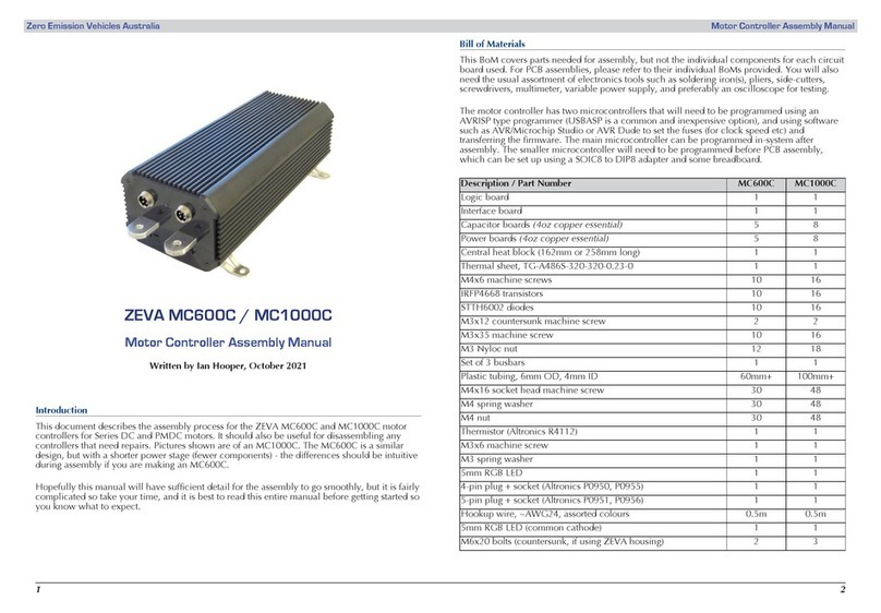
Zeva MC600C User manual

Zeva

Zeva MC600C User manual

Zeva EVMS Lite User manual

Zeva

Zeva EVMS Lite User manual

Zeva MC1000C User manual

Zeva

Zeva MC1000C User manual

Zeva MC1000SP User manual

Zeva

Zeva MC1000SP User manual

Popular Controllers manuals by other brands

RDS PS 8000 Operation

RDS

RDS PS 8000 Operation

HHGK SCH-I user manual

HHGK

HHGK SCH-I user manual

Transcension SDC 824 user manual

Transcension

Transcension SDC 824 user manual

Quickie DX2-REM48 user manual

Quickie

Quickie DX2-REM48 user manual

Hach sc100 user manual

Hach

Hach sc100 user manual

Evco Vcolor 229 M Series instructions

Evco

Evco Vcolor 229 M Series instructions

Balboa Water Group HydroAir 20-0344 manual

Balboa Water Group

Balboa Water Group HydroAir 20-0344 manual

EasyIO FS Series User reference

EasyIO

EasyIO FS Series User reference

Paxton Switch2 How to program

Paxton

Paxton Switch2 How to program

Sony PlayStation DualSense Edge instruction manual

Sony

Sony PlayStation DualSense Edge instruction manual

Danfoss WP75- RF Installation & user's instructions

Danfoss

Danfoss WP75- RF Installation & user's instructions

Raypak RayTemp Hot Water Energy Management Control Installation and operating instructions

Raypak

Raypak RayTemp Hot Water Energy Management Control Installation and operating instructions

Yale ZAPI MPW045-E maintenance

Yale

Yale ZAPI MPW045-E maintenance

iSysmart SGZA10 user manual

iSysmart

iSysmart SGZA10 user manual

Honeywell VR8300 manual

Honeywell

Honeywell VR8300 manual

nVent RAYCHEM 465 Installation, operation and maintenance manual

nVent RAYCHEM

nVent RAYCHEM 465 Installation, operation and maintenance manual

Hastings VT-5 instruction manual

Hastings

Hastings VT-5 instruction manual

Kystar LS4Pro manual

Kystar

Kystar LS4Pro manual

manuals.online logo
manuals.online logoBrands
  • About & Mission
  • Contact us
  • Privacy Policy
  • Terms and Conditions

Copyright 2025 Manuals.Online. All Rights Reserved.