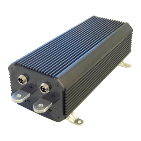
Zeva MC1000SP User manual

Zero emission
Vehicles AustrAliA
http://www.zeva.com.au
MC1000SP
150VDC 1000A motor controller
for Series DC and PM DC motors
TABLE OF CONTENTS
page
1) Introduction 1
2) Safety Warning 1
3) Tech Support and Warranty Information 1
4)FeaturesandSpecications 2
5) Installation 3
6) Power Wiring 4
7) Control Wiring 6
8) Operation 8
9) Customising your Settings 10
INTRODUCTION
Congratulations on your purchase of a ZEVA MC1000SP motor controller.
The MC1000SP represents the culmination of many years development, utilising the latest in power
semiconductorstocreateoneofthemostefcientEVmotorcontrollersavailable–over99%at
all times. Also featuring dual microprocessors for redundant safety, an advanced throttle algorithm
for the smoothest driving experience, silent operation at all times, a compact weather-resistant air-
cooledhousing,andcongurableoperatingparametersviasimpleserialconnection.
Wehopeitprovidesyouyearsofreliableservice.
SAFETY WARNING
Electric vehicle motor controllers are high powered devices which involve potentially lethal
voltages and currents. Proper precautions and electrical safety procedures should always be
observed,voltagesabove110VDCshouldbeconsidereddangerous,andvehiclesshouldnever
beworkedonwhilemaincontactor(s)areengaged.Pleasereadthismanualcarefullybeforeusing
the controller to ensure correct installation and operation. If you are unsure of anything, please
contactusbeforeproceeding.
Wehaveendeavouredtomakeasafeandreliableproductwhichperformsasdescribed,however
since ZEVA has no control over the integration of its products into a vehicle, we can assume no
responsibilityforthesafetyorfunctionalityofthecompletedvehicle.
Itisuptotheendusertodeterminethesuitabilityoftheproductsforthepurposeemployed,and
theenduserassumesallrisksassociated.Productsshouldonlybeinstalledbysuitablyqualied
andexperiencedpersons,andshouldalwaysbeusedinasafeandlawfulmanner.
TECH SUPPORT AND WARRANTY INFORMATION
TheMC1000SPmotorcontrolleriscoveredbya12monthwarrantyagainstmanufacturingfaults
or failures under normal operating conditions. The warranty does not cover misuse of the product,
including but not limited to: excessive voltage or reversed polarity on input terminals, short
circuits on output terminals, excessive voltages applied to control wiring, opening of housing and/
ormodicationofinternals,severeimpactdamage(e.gduetovehiclecrashes),submersion in
water.
Wehavetakengreat careto designasafe andreliable product,butfaults canhappen. Ifyou
believe your motor controller has a fault, please contact us via our website to discuss. If it is
determinedthatahardwarefaultisthelikelycause,wewillprovideanRMAnumberandreturn
address to proceed with repairs.
Ifyouhaveanyquestionsnotcoveredbythismanual,pleasecontactusviaourwebsite:
http://www.zeva.com.au/Contact
1

FEATURES AND SPECIFICATIONS
FEATURES:
Smooth,hybridthrottleresponseforfamiliardrivingfeel•
Thermalcutbackandover-tempprotection•
Congurableparametersviaserialprogrammingcable•
MulticolourstatusLEDplusoptionalremotestatusLED•
Tough,weather-resistantaluminiumhousing(approxIP44)•
Compatiblewithoptionalexternalwatercoolingblockforhighersustainedpower•
Adjustablemotoridlingfunctionforautomaticgearboxesormaintainingauxiliaries•
Supportformostthrottletypesincluding3-wire0-5V,2-wire0-5KΩ,andHEPApedals.•
Fully isolated logic and power electronics•
RobustI/Oprotectscontrolleragainstexternalwiringfaults•
Highpedallockout(protectsagainstnon-zerothrottleonstartup)•
Self diagnostics with error detection including overcurrent, low voltage on power and logic•
supplies, internal parameter corruption, and internal sensor faults.
Independenthardwareovercurrentprotectionsystem(“desat”detection)•
SPECIFICATIONS:
Batteryvoltagerange:12-144Vnominal(9-180Vabsolutemaximum)•
Max 45x LiFePO4 cells, 40x LiCo cells, 12x 12V lead acid
Currentrating:1000Apeak(1minute),300Acontinuous•
Power:150kWpeak,45kWcontinuous•
Powerdevicetype:MOSFET•
On-statevoltagedrop:0.6Vatfullpower,0.2Vatcontinuousrating•
Switchingfrequency:16KHz•
Operatingtemperature:-20˚Cto90˚C(thermalcutbackfrom60˚C)•
Logicpowersupply:12Vnominal(8-18Vrange),200mAmax,internallyfused•
Dimensions:310x130x95mmhousingonly,365x156x106mmincterminalsandbrackets•
Weight:4.5kg•
PACKAGE CONTENTS:
1x MC1000SP motor controller•
4xM8x25bolts,washers,andnuts•
1x 5-pin plug, 1x 6-pin plug•
1xUSB-Serialprogrammingcable•
1xRGBLEDforremotestatuslight•
1x User manual•
INSTALLATION
Themotorcontrollermaybeinstalledinanyorientation.Usually,installationclosetothemotor
isbestinordertokeeppowerwiringtothemotorshort.Theenclosureisweatherresistantbutnot
100%waterproof,soitisbestinstalledinalocationwithsomeprotectionfromtheelements.Ifit
maybeinthedirectpathofwater,splashguardsarerecommended.
Thecontroller’scontinuouspowercapabilitiesdependsomewhatontheamountofairowaround
thecaseforconvectioncooling.Iftheinstalllocationhasverylittleairow,thecontrollermay
benetfromaddedconvectioncoolingviafansorducting.(Orforhighestsustainedpower,the
controllermaybebase-mountedtoawatercoolingblock.)
Controller dimensions and mount locations
Themotorcontrollercomeswithbracketsformountingwithfour6mmor1/4”boltsona142
x 260mm spacing. Flat washers and spring washers under the heads of mounting bolts are
recommendedtopreventtheboltsfromlooseningovertimeduetovibration.
Alternativelythemountingbracketsmayberemoved,andthefourholesunderneaththehousing
usedtofastentoapanelfrombeneath.TheholesareM6threadona70x260mmspacing.
Caution: Since these threaded holes penetrate the housing, ensure that bolts do
not extend more than 20mm into the case or they may damage components inside!
32

POWER WIRING
REMEMBER..
The traction circuits in electric vehicles involve very high power levels, with potentially lethal
voltagesandcurrentsinvolved.Alwaysobserveproperprecautionsandsafetyprocedureswhen
workingonelectricvehicles.Alwayswearsafetyglasses,useinsulatedtoolswherepossible,and
checkfordangerousvoltageswithamultimeterbeforeundertakinganymaintenance!
Ifyouareunsure,alwaysconsultwithanexperiencedEVtechnicianbeforeproceeding.
TYPICAL WIRING DIAGRAM
Thediagrambelowshowsthebasicpowerwiring.Orangelinesrepresentpowercables,which
shouldbe50sqmmor1/0AWGinsize,orlarger.Controlwiringto/fromcontrollernotshown.
Basic power wiring diagram for MC1000SP controller
Caution: Always double check power wiring before turning the system on for the
rst time, because reversed polarities or short circuits can do a lot of damage!
When rst powering up the completed system, wiring mistakes or faulty throttle
devices could cause unexpected power to the motor, which risks injury or vehicle
runaway. It is highly recommended that the drive wheels be off the ground, and
that nobody is standing in front of or behind the vehicle at the time.
TIPS FOR BEST PERFORMANCE
Power cables around 50sqmm or 1/0AWG in size are recommended for all power wiring•
betweenbatteriesandmotorcontroller,and50-95sqmm(1/0to4/0AWG)cablebetweenthe
motorcontrollerandmotor,whereaveragecurrentsarehigher.Itisbesttousedoubleinsulated
cablewithanorangesheathforcompliancewithelectricalstandards.
Ensure all power terminals and connections in your traction circuit are clean and tight. Always•
useeitherspringwashersorNylocnutstoensureconnectionswillnotloosenfromvibration
overtime.Poorconnectionshavea higher resistance, whichcancausethemtobecomehot
whenconductinglargecurrents–inextremecases,causingdamagetocomponents.
It is essential to have a precharge device to charge up the motor controller’s internal capacitor•
bankbeforeclosingthemaincontactor.Closingthemaincontactorwithoutrstprecharging
thecontrollercausesahugecurrentspikewhichdamagescontactors,typicallyweldingtheir
contactstogether.A1KΩ10Wprechargeresistorpermanentlyacrossthemaincontactorcan
work,butisnotthesafestsolutionasdoesnottrulyisolatethecontrollerwhenthekeyisoff,
anditwillmaintainvoltageonthecontrolleratalltimes.Abettersolutionisa2-stageautomatic
prechargersuchasourZEVASmartPrecharger,oranEVMSwithbuilt-inprecharger.
Ensure you have an appropriately rated main contactor and fuse protecting your traction circuit.•
Examples of suitable contactors are the Kilovac EV200 or LEV200, Gigavac GX14,Albright
SW200, or Nanfeng ZJW400A.
Forafuse,a500AsemiconductortypewithsufcientDCvoltageratingisrecommended,such•
asthosefromBussmann,Ferraz-Shawmut,Mersen,Littelfuse,etc.Largefusestendtobevery
slowtoblow,typicallyabletocarrytwicetheirratedcurrentforabout1minute.Assuchitis
besttouseafusewitharatingslightlyabovethecontinuousratingofthemotorcontroller,rather
than one rated for the maximum motor controller current.
TheMC1000SPmotorcontrollerusesaluminiumbusbars.Aluminiumitselfisagoodconductor•
ofelectricity,butunfortunatelythe (invisible)aluminium oxidewhichforms on itssurfaceis
a poor conductor. The power terminals are supplied cleaned and with a thin layer of Noalox
contactpasteappliedtopreventre-oxidation.Thispasteshouldbeleftontheterminalswhen
areattachingpowercables.(Theforceoftighteningtheboltswillpushthegreaseoutandseal
the contact area.)
The power cables in electric vehicles carry a large amount of power, and can emit a lot of•
electromagneticinterference(EMI)dependingontheirphysicallayout.TominimiseEMI,itis
besttokeepthepositiveandnegativecablesclosetogether–boththepowercablesfrombattery
packtocontroller,andcontrollertomotor.TofurtherreduceEMI,thecablesmaybetwisted
aroundeachother.(ForfurtherdetailsonwhytwistingcablestogetherishelpfulforEMI,referto
http://www.wikipedia.com/wiki/Twisted_Pair)
54

CONTROL WIRING
PLUG IDENTIFICATION
TheMC1000SPusestwoaviation-stylescrew-lockplugsforallcontrol/lowpowerconnections,
onewith5pinsforthepowerinputandstatusLEDoutputconnections,andtheotherwith6pins
forthethrottleandserialprogrammingconnections.Thediagrambelowshowspinidentications
as viewed on the controller case.
Gnd
12V
B
G
R
5V
Gnd
ThrB
ThrA
Rx
Tx
LED
Identication of pins on control wiring plugs Pins for remote LED
Plug 1:
5V:Outputpowersupplyforthrottleand/•
or serial communications devices. Max
50mAoutput(internallyfused,w/reset)
Gnd:Groundconnectionforthrottle•
ThrottleA:Firstthrottleinput,usuallythe•
analog level, 0-5V input
Throttle B: Second throttle input, either•
enableswitchor2ndanalog,0-5Vinput
Tx/Rx:Transmitandreceivepinsforserial•
communications, 5V TTL
Plug 2:
12V:Connecttoakey-switched12Vsupply•
sothecontrollercomesonwhenthekeyis
turned on. Often wired in parallel with your
main contactor. Maximum voltage range
8-18V input
Gnd:Connecttoground/vehiclechassis•
R/G/B: Red, green and blue channels for•
statusLEDoutput.5Voutputs,2KΩoutput
impedance (max 2.5mA). Gnd terminal
of LED is grounded to chassis (or shares
ground pin on same plug).
WIRING UP THE PLUGS
The plugs are opened using a small jewellers screwdriver to remove the screw on the side of the
rearshell,whichthencomesawaywithasmallcounterclockwisetwist.
Feedwiresthroughthebackoftherearshellbeforeattachingtothepinstoensurethecasecan
gotogetheragainafterwiresareattached.Forreliableconnections,besureto“tin”(addsolderto)
boththewiresandthecontactsbeforesolderingthemtogether.
Theshellalsohasacablestressreliefclampattherearwhichcanbefasteneddowntoholdthe
cables.Ifyourcablesaretoosmallfortheclamptoengage,youcanwrapsomeinsulationtape
aroundthemtoincreasethediameterandensuretheclampisabletoholdtheminplace.
Plugs for control wiring: Disassembled (left), wiring (middle), complete (right)
Sincethelogicwiringisnecessarilyquiteclosetothetractioncircuitpowercables,toavoid•
ElectromagneticInterference(EMI)itisbesttouseshieldedcables,ortwistwires(suchas12V
andGround)together.Alsoavoidrunninglogicwiringinparallelwithpowercablesforlong
distances,asitincreasesnoiseduetocrosstalk.
Thelogicboardonlyrequires200mAcurrent,soassmallasAWG28wiremaybeusedforthe•
powersupply.However,ifnotenclosedinashieldedsheath,itisbesttouselargercablearound
18AWG+forbettermechanicalstrength/durability.
All control wiring is galvanically isolated from the power terminals. In most cases the control•
wiringwillshareacommonground(thevehiclechassis)withyourvehicle’sexisting12Vsystem,
and the traction circuit should remain electrically isolated for safety.
THROTTLE DEVICE
The MC1000SP controller supports a variety of different throttle types.
Type 1, 0-5V Hall Effect throttle:• Any throttle device which outputs a 0-5V level representing
0-100%throttlemaybeused.Non-contact Hall Effecttypesarethebestoption due to their
reliabilityandvirtuallyunlimitedlifespan.TheyshouldhavethreewirestoconnecttoGnd,5V
andThrottleA(0-5Vlevel).TheThrottleBpinshouldbeconnectedto5Vthroughtheenable
switchonthepotbox(COMandNCterminals)forredundantsafetyincaseofhallsensorfault.
Type 2, 2-wire 0-5KΩ: • Although not considered a great option due to their tendency to wear
outandbecomeunreliableovertime,legacy2-wireresistive0-5KΩpotboxes(suchastheCurtis
PB-6)canbeused.ThetwothrottlewiresconnecttoThrottleAand 5V (either polarity).The
enableswitchshouldbewiredbetween5VandThrottleB,usingtheCOMandNCterminals.
ThecontrollerwillhavetobeprogrammedviaserialinterfaceforThrottleType2.
Type 3, Hall Effect Pedal Assembly (HEPA):• HEPApedalsarebecomingtheindustrystandard
forthrottledevicesinvehiclesastheyofferhighreliabilityandsafetythroughtheuseofdual
(redundant)halleffectsensors.AvarietyofdifferentHEPApedalsareavailable,typicallyhaving
6 wires for two independent 3-wire hall effect type throttles. The MC1000SP was designed to
workwiththoseprovidingdualanalogoutputsofaround0.7V–3.5Vand1.4V–4.2V.Usethe
Gndand5VpinsonPlug2toprovidepowertobothsensors.The0.7-3.5Vsignalconnectsto
ThrottleAandthe1.4V-4.2VsignaltoThrottleB.WithaHEPAthrottle,thecontrollercandetect
a throttle fault if any four of the wires are disconnected, or if either of the throttle sensors are
faulty.BesuretocongurethecontrollerforThrottleType3.
76

OPERATION
TIPS FOR BEST PERFORMANCE
Manydriversareaccustomedtokeepingrevslowintheirpetrolvehiclesinordertomaximise
efciency,sincepetrolenginesareveryinefcientathighrevs.Well,electricdrivesystemsarethe
otherwayaround!Thesinglemosteffectivewaytomaximiseperformancefromyourmotorand
controlleristokeepyourmotorrevshigh–around3000-4000rpmwithmostSeriesDCmotors.
Foragivenpoweroutput,drivinga motorat higherspeed uses more voltagebut lesscurrent,
whichreducescopperlossesinthemotorandresistiveheatinginthecontroller.Droppingdown
agearreducesmotorampsbyabout30%,whichcanactuallyhalvetheheatgeneratedinyour
controller–andhencedoublethecontinuouspowercapability.(Caution:MostSeriesDCmotors
areratedto5000rpmmaxsobecarefulnottoexceedthisspeed!)
THERMAL PROTECTION
Ifyourcontrollerheatsinktemperaturereachesabout70˚C(150˚F),thecontrollerwillcommence
thermalcutback,smoothlyreducingpowertomitigatefurtherheating.ThestatusLEDwillash
green/redwhileinthisstate.Ifthecontrollertemperaturereaches90˚C(200˚F),thecontrollerwill
shut down completely to avoid overheating which could damage components.
The controller’s power rating depends somewhat on airow to cool the housing. If you are
experiencingthermalcutbacks,itmaybeusefultoaddfansorductstoincreaseairow.Driving
more slowly and keeping motor revs high will also help keep the motor controller cooler. If
thermalproblemspersist, it maybe useful toadda watercooling systemorexternal heatsink,
whichcanbematedtothebaseofthecontroller(withthermalpasteinbetween).
12V LOGIC SUPPLY
The MC1000SP has an internal regulated power supply on its 12V input which allows it to operate
safelyandcorrectlyoveraninputvoltagerangeof8-18VDC.Asasafetyprecaution,thecontroller
willshutdownifitdetectsthecontrolvoltageinputdipbelow8V.
Inmostinstallationsthiswillneverhappen,butifyour12Vbatteryand/orDC/DCconverterisvery
weak,thevoltagemaydipwhenloadssuchasheadlightsareturnedon,whichcantripoutthe
motorcontroller.Thisshouldberectiedbybyttingastrongerbatteryand/orDC/DCconverter.
MOTOR IDLING FUNCTIONALITY
TheMC1000SPincludesabasicmotoridlefunctionality,basedonalowtargetspeedwithlow
torquelimit.ItdoesnotuseanRPMsensorforspeedfeedback,sothespeedmayvarydependingon
load.HoweveritisasimpleandeffectivesolutionforEVconversionswithautomatictransmissions
(whichrequirethemotortokeepturningtomaintainoilcirculationinthegearbox),orforvehicles
using OEM power steering pumps, air-conditioning compressors, alternators, etc.
The idle speed and torque are congured via serial programming.Voltage effectively controls
targetmotorspeedandcurrentcontrolsthetorqueitwillusetogetthere.Idealvalueswilldepend
onyourmotorandvehicle,butagoodstartingpointis6Vidlevoltageand100Aidlecurrent.
Caution: Electric motors can suffer damage if they remain stalled with current
owing for extended periods of time. Idle functionality is NOT recommended for
“direct drive” vehicles, and in the case of vehicles with manual transmissions, be
sure to put the clutch in when coming to a stop.
INTERNAL CAPACITOR WARNING
Motorcontrollershavealargebankofcapacitorsontheirinput,whichcanretainitschargefora
longtimeafterthecontrollerispoweredoff.Exercisecautionifundertakingvehiclemaintenance
soonafterdriving,astheremaybesignicantvoltageacrossthecontroller’sinputpowerterminals,
even if your main contactor is open. Always measure the voltage across the controller with a
multimeterbeforeperforminganymaintenance.
LED STATUS AND ERROR CODES
TheMC1000SPhasanRGBstatusLEDonitsfrontpanel,andtheoptionforaremotestatusLED
wiredtoyourvehicle’sdash.ThisLEDcanprovidevisualfeedbackonthecontroller’soperating
status.Thefollowingtablesummarisesthecodesyoumayencounter(multipledotsrepresenting
aashsequence):
LED Code Condition Comment
Controller on (Noerrors)
Thermalcutback Controllertemperatureabove60˚C.Powerreduces
slowly towards thermal shutdown threshold.
Thermal shutdown Controllertemperatureabove90˚C.Thermal
shutdown until temperature reduces.
Battery voltage low Voltageatpowerterminalsbelowminimumsetting.
Powerstagedisableduntilvoltageincreases.
Supply voltage low Supplyvoltagebelow8VDC.Latchesonforsafety.
Fix 12V supply then power cycle controller.
Throttle error Invalid voltage or level mismatch on throttle. Error
latchesonforsafetyuntilzerothrottleisdetected.
Highpedallockout Non-zerothrottledetectedatstartup.Mayindicate
foot on pedal, or a faulty throttle device.
Corrupt settings Fault in the internal memory. Will automatically
revert to default settings on next startup.*
Desaterror Hardwareovercurrentfault.Mayindicatedamageto
internal power devices or short circuit in motor.*
98

Internal sensor fault An internal sensor returned an invalid value.*
*Theserareerrorsmayindicateahardwarefaultinthecontroller–pleasecontactus!
Caution: There are no user-serviceable parts inside the controller.
Do not attempt to open the controller as this will void warranty!
CUSTOMISING YOUR SETTINGS
TheMC1000SPstoresavarietyofoperatingsettingsinmemorywhichmaybemodiedbytheuser
viatheprovidedserialprogrammingcable.Itshouldworkwithanypersonalcomputerwhichhas
aUSBportandserialcommunicationssoftware–themostcommonexamplebeingHyperterminal
forMicrosoftWindows.Themotorcontrollercanonlybeprogrammedwhenrstpoweredup.
Onceyoustarttodrive,serialprogrammingwillbeautomaticallydisableduntilthecontrolleris
next turned on.
AUSBtoserialprogrammingcableissuppliedwiththemotorcontroller.Ifyourcomputerdoesn’t
recogniseitwhenyourstplugin,youmayneedtoinstallthedrivers.Acopymaybedownloaded
from:http://www.zeva.com.au/WinSerialDriver.zip
ThefollowingdemonstrateshowtosetupHyperterminal,butshouldbeeasilytranslatedforother
serialcommunicationssoftware.Thebasicsettingsare9600bps,8-bitdata,noparity,1stopbit,
noowcontrol.(NotethattheCOMportnumbermayvary.)
Hyperterminal settings windows
Onceyourconnectionwindowisup,pressEscapeandalistofavailablesettingsshouldappear
asper the followingimage. Press the appropriate number to select a parameter, thentype the
newvalueandpressReturntosave.Theacceptableparameterrangeisshown,andthecontroller
will automatically cap the parameter to this range if an invalid value is entered. At any time,
pressingEscapewillreturn tothemainmenu. Once nished,simplyunplug the programming
cable(settingsaresavedautomatically).
Hyperterminal Connection Window
Minimumbatteryvoltage:Thissettingcanbeusefultoavoidoverworkingorover-discharging•
yourbattery,bysettingittowhatevervoltagerepresentsalowstateofcharge(atbattery).Note
thatthiscannotreplaceaproperbatterymanagementsystemforprotectingyourcells!
Maximummotorvoltage:Ifusingamotorratedtoalowervoltagethanyourbatterypack,you•
can use this setting to ensure that the motor controller will not overspeed the motor.
Maximummotorcurrent:Invehicleswithsmallermotors,youmaywishtoreducemaximum•
motorcurrentinordertoavoiddamagingyourmotorfromovercurrent.Most6”orlargerSeries
DCmotorswillbenewiththemaximum600Asetting.
Maximumbatterycurrent:Ifusingsmallorweakbatteries,youcanadjustthissettingtoavoid•
overworkingyourbatteries.(Thistypicallydoesnoteffectaccelerationwhensettingoff,butmay
reduce high speed performance.)
Throttleramprate:Thisvariesthe rateat whichthe throttleisallowedtorampup.Asetting•
of zero gives instant throttle response, with numbers 1–4 giving increasingly gentle throttle
ramps.
Throttle type:The MC1000SP supports three throttle types: (1)Three wire 0-5V analog plus•
Enable(2)Twowire0-5KΩplusenableand(3)HallEffectPedalAssembly(HEPA).Pleaserefer
totheControlWiring:ThrottleDevicesectionforfurtherdetails.
Idlevoltageandcurrent:Thesecanbeusedtoenablemotoridlingfunctionality.Becarefulto•
leavetheseaszerounlessyouaresureyouneedthem,asitcancausethemotortorunnon-stop!
RefertotheOperation:MotorIdlingsectionformoreinformation.
1110
Table of contents
Other Zeva Controllers manuals
Popular Controllers manuals by other brands

Digiplex
Digiplex DGP-848 Programming guide

YASKAWA
YASKAWA SGM series user manual

Sinope
Sinope Calypso RM3500ZB installation guide

Isimet
Isimet DLA Series Style 2 Installation, Operations, Start-up and Maintenance Instructions

LSIS
LSIS sv-ip5a user manual

Airflow
Airflow Uno hab Installation and operating instructions


