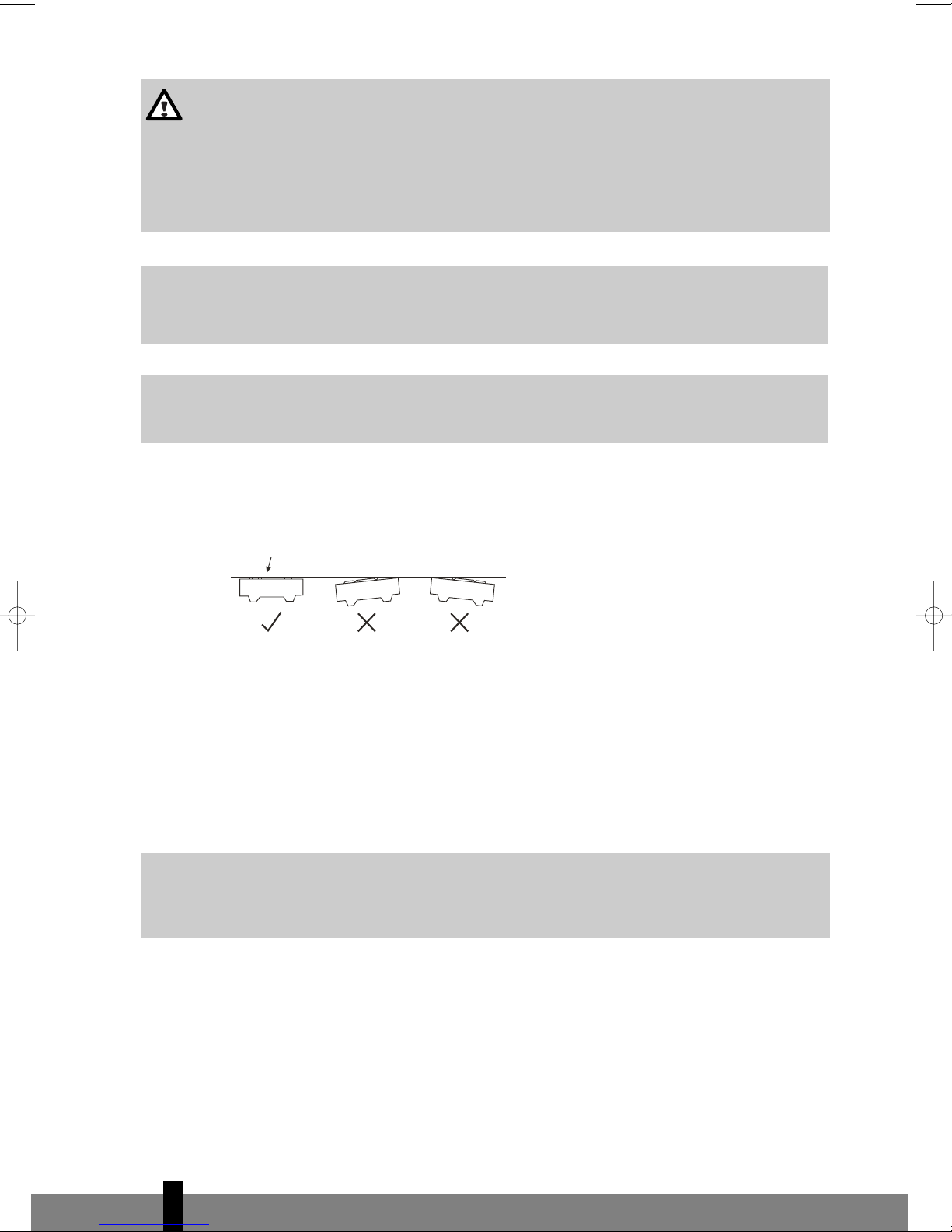
Zibro SC 3050 User manual

S(C) 30xx
Installation Manual
2
5
3
4
1
:
INSTALLATIONS HANDBUCH
MANUAL DE INSTALACIÓN
MANUEL D’INSTALLATION
INSTALLATION MANUAL
INSTALLATIEHANDLEIDING
INSTRUKCJA MONTAŅU
2
22
42
62
82
102
instal_S(C)30xx.qxd 19-07-2010 13:32 Pagina 1

4
62
IMPORTANT NOTICE:
Install this device only when it complies with local/national legislation, ordinances and standards. This pro-
duct is intended to be used as an air conditioner in residential houses and is only suitable for use in dry
locations, in normal household conditions, indoors in living room, kitchen and garage. Check the mains vol-
tage and frequency. This unit is only suitable for earthed sockets, connection voltage 230 V~ / 50 Hz.
This service manual is intended for use by individuals possessing adequate backgrounds of electrical, elec-
tronic, refrigerant and mechanical experience. Any attempt to install or repair the appliance may result in
personal injury and property damage. The manufacturer or seller cannot be responsible for the interpreta-
tion of this information, nor can it assume any liability in connection with its use.
The information, specifications and parameter are subject to change due to technical modifications or
improvement without any prior notice. The accurate specifications are presented on the nameplate label.
• Please read this installation manual completely before installing the product.
• When the power cord is damaged, replacement work shall be performed by authorized personnel
only.
• Installation work must be performed in accordance with all European, national and / or local directi-
ves and standards and must be done by authorized personnel only. The guarantee is invalid for dama-
ge caused by neglect or by actions that deviate from those in this instruction booklet.
•Always make sure to wear the correct personal safety protections such as protective eyewear, gloves,
mouthcaps, ear protection etc.
Internet:
For your convenience you can download the latest version of the user-, installation- and/or service manual
on www.zibro.com
instal_S(C)30xx.qxd 19-07-2010 13:32 Pagina 62

4
63
CONTENTS
SAFETY PRECAUTIONS 64
INSTALLATION OF INDOOR AND OUTDOOR UNITS 65
ELECTRICAL WORK 76
TEST RUNNING 80
G
WARNING!
Do not install, remove and/or reinstall the unit by yourself if you do not have
the adequate electrical, electronic, refrigerant, mechanical experience and
authorisation.
• Improper installation can cause water leakage, electrical shock, refrigerant
leakage or fire. Please consult authorized dealer or specialized air
conditioner engineer for the installation work. Please note faults
caused by improper installation is not covered by warranty.
•Unit must be installed in an easily accessible area. Any additional cost
required to hire special equipment to service the unit will be the
responsibility of the customer
instal_S(C)30xx.qxd 19-07-2010 13:32 Pagina 63

SAFETY PRECAUTIONS
The following should be always observed for safety:
• Be sure to read the following WARNING before installing the airconditioner.
• Be sure to observe the cautions specified here as they include important items related to safety.
• After reading this instructions, be sure to keep it together with the owners manual in a handy place
for future reference.
The air conditioner contains a refrigerant and can be classified as pressurized equipment. Therefore always
contact an authorized air conditioning engineer for installation and maintenance of the air conditioner. The
air conditioner must be inspected and serviced on an annual base by an authorized air conditioning engi-
neer.
G
WARNING
Do not install it yourself.
• Incorrect installation could cause injury due to fire, electric shock, the unit falling or leakage of
water. Consult your dealer from whom you purchased the unit or an authorised installer.
Install the unit securely in a place which can bear the weight of the unit.
• When installed in an insufficiently strong place, the unit could fall causing injury.
Use the specified electrical wires to connect the indoor and outdoor units securely and attach the
wires firmly to the terminal board connecting sections so the stress of the wires is not applied to
the sections.
• Incorrect connection and fixing could cause a fire.
Be sure to use the provided or specified parts for the installation work.
• The use of defective parts could cause an injury due to a fire, electric shock, the unit falling, etc.
Perform the installation securely referring to the installation instruction.
• Incorrect installation could cause a personnel injury due to fire, electric shock, the unit falling
or leakage of water.
Perform electrical work according to the installation manual and be sure to use an
exclusive circuit.
• If the capacity of the power circuit is insufficient or there is incomplete electrical work, it could
result in a fire or an electric shock.
Check that the refrigerant gas does not leak during installation or after installation is completed.
• Leaking refrigerant is bad for the environment and could cause global warming.
Attach the electrical part cover to the indoor unit and the service panel to the outdoor unit
securely.
• If the electrical part covers off the indoor unit and/ or the service panel of the outdoor unit are
not attached securely, it could result in a fire or electrical shock due to dust, water, etc.
4
64
instal_S(C)30xx.qxd 19-07-2010 13:32 Pagina 64

4
65
INSTALLATION OF INDOOR AND OUTDOOR UNITS
Read completely, then follow step by step.
Fig. 1
Indoor unit
• Do not expose the indoor unit to heat or steam.
• Select a place where there are no obstacles in front or around the unit.
• Make sure that condensation drainage can be conveniently routed away continuously going down-
wards.
• Do not install near a doorway.
• Ensure that the space on the left and right of the unit is more than 12cm.
• Use a stud finder to locate studs to prevent unnecessary damage to the wall.
• The top of the indoor unit should be installed on the wall at a height of 2.3 metres or more from the floor.
• The indoor unit should be installed allowing a minimum clearance of 15cm from the ceiling.
• Any variations in pipe length will/may require adjustment to refrigerant charge.
Fig. 2
LEFT
More than 30 cm.
BACK
More than 30 cm.
RIGHT
More than 60 cm.
FRONT
More than 200 cm.
More than 60 cm.
More than 15 cm.
More than 12 cm. More than 12 cm.
2.3 m or more
G
CAUTIONS
This equipment must be earthed and installed with an earth leakage breaker. It can possibly cause
electrical shock if grounding is not perfect.
Do not modify the length of the power supply cord. Do not use an extension cable. Otherwise it
can cause electric fire or shock.
Do not install the unit in a place where a flammable gas leaks.
• If gas leaks and accumulates in the area surrounding the unit, it could cause an explosion.
Perform the drainage/piping work according to the installation instruction.
• If there is a defect in the drainage/piping work, water could leak from the unit and household
goods could get wet and be damaged.
instal_S(C)30xx.qxd 19-07-2010 13:32 Pagina 65

Outdoor unit
• If an awning is built over the outdoor unit to prevent direct sunlight or rain exposure, make sure that
heat radiation from the condenser is not restricted.
• Ensure that the clearance around the back of the unit is more than 30cm and left side is more than
30cm. The front of the unit should have more than 200cm of clearance and the connection side (right
side) should have more than 60cm of clearance. (See picture 2)
• Do not place animals and plants or other obstacles in the path of the air inlet or outlet.
•Take the air conditioner weight into account and select a place where noise and vibration will not be
an issue.
• Select a place so that the warm air and noise from the air conditioner do not disturb neighbours.
• Note that the outdoor unit produces sound when in use, this could interfere with local legislation. It
is the responsibility of the user to check and to make sure the equipment is in full compliance with
local legislation.
• Be sure to level the unit.
GENERAL
• Ensure the support structure and anchoring method are adequate for the unit location.
• Consult and follow local legislation regarding mounting and installation of air conditioner equip-
ment.
• If the outdoor unit is installed on roof structures or external walls, this may result in excessive noise
and vibration and may also be classed as a non serviceable installation.
• Always place the airconditioner in an easy accessible position.
ITEMS PACKED WITH THE UNIT (for SC 30xx models)
Number Name of Accessories Quantity
1 Installation plate 1
2 Clip Anchor 8
3Self-tapping screw ‘A’ ST 3.9x25 8
4 Seal 1
5 Drain joint 1
6 Connecting pipe assembly 1
7 Remote controller 1
8 Self-tapping screw ‘B’ ST 2.9x10 2
9 Remote controller holder 1
4
66
instal_S(C)30xx.qxd 19-07-2010 13:32 Pagina 66

4
67
ITEMS PACKED WITH THE UNIT (for S 30xx models)
Fig. 3
8
9
7
C
B
A
6
2
3
1
15 cm or more
12 cm or more
12 cm or more
Air filter
LEFT
30 cm or more
Air outlet
60 cm above
FRONT
200 cm or more BACK
30 cm or more
RIGHT
60 cm or more
Loop the
connective cable
Remote Controller
Mounting screw B
ST2.9x10-C-H
Remote controller holder
G
NOTE!
Except the above provided parts, the other parts needed during installation are to be purchased
separately by the buyer of the airconditioner.
Number Name of Accessories Quantity
1Installation plate 1
2Clip Anchor 8
3 Self-tapping screw ‘A’ ST 3.9x25 8
4Seal 1
5Drain joint 1
6
Connecting pipe
assembly
Liquid side Ø6.35
Not includedGas side
Ø 9.53 (< 3.5 kW model)
Ø12.7 (≥ 3.5 kW model)
7 Remote controller 1
8 Self-tapping screw ‘B’ ST 2.9x10 2
9 Remote controller holder 1
instal_S(C)30xx.qxd 19-07-2010 13:32 Pagina 67

INDOOR UNIT INSTALLATION
1. Fit the installation plate
1. Fit the installation plate ahorizontally on structural parts of the wall with spaces around the installa-
tion plate.
2. If the wall is made of brick, concrete or the like, drill eight (8) 5mm diameter holes in the wall. Insert
Clip anchor bfor appropriate mounting screws c.
3. Fit the installation plate a on the wall with eight (8) type “A” screws c.
G
NOTE
Fit the Installation Plate and drill holes in the wall according to the wall structure and
corresponding mounting points on the installation plate. (Dimensions are in “mm” unless
otherwise stated)
270~370
878
659 133
40
40
270 27
6
55 55 39
70
750
45
250
70
------------------------
293
920
50
50
815
40 285
90
40
45
------------------------
Correct orientation
of Installation Plate
G
ATTENTION
Copper lines must be insulated independently from each other.
G
ATTENTION
This illustration is for explanation and indication purposes only. The illustration may be different
from the airconditioner you purchased.
CAUTION
• Ensure that the space around the left and right of the indoor unit is more than 12cm.
The indoor unit should be installed allowing a minimum clearance of 15cm from the ceiling.
• Use a stud finder to locate studs to prevent unnecessary damage to the wall.
• The indoor unit should be installed on the wall at a height of 2.3 metres or more from the
floor.
• At least two of the directions A, B and C should be free from obstructions.
4
68
instal_S(C)30xx.qxd 19-07-2010 13:32 Pagina 68

4
69
S3025
SC 3025
S 3032
SC 3032
instal_S(C)30xx.qxd 19-07-2010 13:33 Pagina 69

S 3050
SC 3050
Fig. 4
Fig. 5
2. Drill a hole in the wall
1. Determine hole positions according to the diagram detailed in Fig.5. drill one (1) hole (≥85 mm for
SC30xx / ≥65 mm for S30xx) slanting slightly downwards to outdoor side, this will prevent water to
come indoors.
2. Always use wall hole conduit when drilling metal grid, metal plate or the like.
3. Connective pipe and drainage installation
G
Always run the drain hose sloping downward all the way. Do not install the drain hose as
illustrated below.
270~370
878
659 133
40
40
270 27
6
55 55 39
70
750
45
250
70
------------------------
293
920
50
50
815
40 285
90
40
45
------------------------
Wall
Indoor
Outdoor
≥5°
5- 7 mm
per 100 mm
4
70
instal_S(C)30xx.qxd 19-07-2010 13:33 Pagina 70

4
71
Fig. 6
1. When connecting extension drain hose, insulate the connecting part of extension drain hose with a
shield pipe, do not let the drain hose slack.
Fig. 7
Connective pipe
2. For the left-hand and right-hand piping, remove the pipe cover from the side panel. The pipe cover
must be kept as it may be used when relocate the air conditioner to any other place.
Fig. 8
4. Indoor unit installation
For SC 30xx models
1. Pass the piping through the hole in the wall.
2. Put the upper claw at the back of the indoor unit on the upper hook of the installation plate, move the
indoor unit from side to side to see that it is securely hooked.
3. The female half can be easily past through by lifting the indoor unit with a cushioning material bet-
ween the indoor unit and the wall. Get it out after finishing it.
4. Push the lower part of the indoor unit up on the wall. Then move the indoor unit from side to side, up
and down to check if it is hooked securely.
G
ATTENTION
Always use the highest care when bending the piping. Make sure that the piping always is
bended and not nodded. In case of a nodded pipe: do not attempt to install this nodded pipe as
this is a potential refrigerant leak.
.
.
.
.
.
.
.
.
.
.
.
.
.
.
.
.
.
.
.
.
.
.
.
.
.
.
.
.
.
.
.
.
.
.
.
.
.
.
.
.
.
.
.
.
.
.
.
.
.
.
.
.
.
.
.
.
.
.
.
.
.
.
.
.
.
.
.
.
.
.
.
.
.
.
.
.
.
.
.
.
.
.
.
.
.
.
.
.
.
.
.
.
.
.
.
.
.
.
.
.
.
.
.
.
.
.
.
.
.
.
.
.
.
.
.
.
.
.
.
.
.
.
.
.
.
.
.
.
.
.
.
.
.
.
.
.
.
.
.
.
.
.
.
.
.
.
.
.
.
.
.
.
.
.
.
.
43
Pipe holder
Pipe Cover (left)
Left piping
Left back piping
Right back piping
Right piping
Pipe Cover (right)
.
.
.
.
.
.
.
.
.
.
.
.
.
.
.
.
.
.
.
.
.
.
.
.
.
.
.
.
.
.
.
.
.
.
.
.
.
.
.
.
.
.
.
.
.
.
.
.
.
.
.
.
.
.
.
.
.
.
.
.
.
.
.
.
.
.
.
.
.
.
.
.
.
.
.
.
.
.
.
.
.
.
.
.
.
.
.
.
.
.
.
.
.
.
.
.
.
.
.
.
.
.
.
.
.
.
.
.
.
.
.
.
.
.
.
.
.
.
.
.
.
.
.
.
.
.
.
.
.
.
.
.
.
.
.
.
.
.
.
.
.
.
.
.
.
.
.
.
.
.
.
.
.
.
.
.
43
Upper Hook
Lower Hook
Cushion
material
.
.
.
.
.
.
.
.
.
.
.
.
.
.
.
.
.
.
.
.
.
.
.
.
.
.
.
.
.
.
.
.
.
.
.
.
.
.
.
.
.
.
.
.
.
.
.
.
.
.
.
.
.
.
.
.
.
.
.
.
.
.
.
.
.
.
.
.
.
.
.
.
.
.
.
.
.
.
.
.
.
.
.
.
.
.
.
.
.
.
.
.
.
.
.
.
.
.
.
.
.
.
.
.
.
.
.
.
.
.
.
.
.
.
.
.
.
.
.
.
.
.
.
.
.
.
.
.
.
.
.
.
.
.
.
.
.
.
.
.
.
.
.
.
.
.
.
.
.
.
.
.
.
.
.
.
43
Do not block water flow by a rise.
Do not put the end of drain hose
into water.
instal_S(C)30xx.qxd 19-07-2010 13:33 Pagina 71

Fig. 9 Fig. 10
For S 30xx models
For the rear-right-hand and rear-left-hand piping, install the piping as shown. Bend the connective pipe
to be laid at 43mm height or less from the wall. (fig. 9 and 10)
1. Pass the piping through the hole in the wall.
2. Put the upper claw at the back of the indoor unit on the upper hook of the installation plate, move the
indoor unit from side to side to see that it is securely hooked.
3. Piping can easily be made by lifting the indoor unit with a cushioning material between the indoor unit
and the wall. Get it out after finish piping.
4. Push the lower part of the indoor unit up on the wall. Then move the indoor unit from side to side, up
and down to check if it is hooked securely.
See picture 11:
Bending the refrigerant piping at the back of the unit needs to be done with the highest care! The piping con-
sists out of cupper. When bending the highlighted part more than 1 time the Cupper will start cracking due
to a physical process. Cracking can cause leakage refrigerant leakage and is not covered by the warranty.
Fig. 11
5. Piping and wrapping
Bundle the tubing, connecting cable, and drain hose with tape securely, evenly as shown in Fig.9.
G
ATTENTION
• Because the condensed water from rear of the indoor unit is gathered in ponding box and is
piped out of room. Do not put anything else in the box.
• Connect the indoor unit first, then the outdoor unit. (S 30xx)
Do not bend!
Bend
(Only 1 x)
Bend
(Only 1 x)
.
.
.
.
.
.
.
.
.
.
.
.
.
.
.
.
.
.
.
.
.
.
.
.
.
.
.
.
.
.
.
.
.
.
.
.
.
.
.
.
.
.
.
.
.
.
.
.
.
.
.
.
.
.
.
.
.
.
.
.
.
.
.
.
.
.
.
.
.
.
.
.
.
.
.
.
.
.
.
.
.
.
.
.
.
.
.
.
.
.
.
.
.
.
.
.
.
.
.
.
.
.
.
.
.
.
.
.
.
.
.
.
.
.
.
.
.
.
.
.
.
.
.
.
.
.
.
.
.
.
.
.
.
.
.
.
.
.
.
.
.
.
.
.
.
.
.
.
.
.
.
.
.
.
.
.
43
Indoor unit outline Connective pipe
Indoor unit
Ponding box
Pipe room
Connective pipe
Wrapping belt
Connective cable
Drain hose
4
72
instal_S(C)30xx.qxd 19-07-2010 13:33 Pagina 72

4
73
OUTDOOR UNIT INSTALLATION
Outdoor installation precaution
• Install the outdoor unit on a rigid base to prevent increasing noise level and vibration.
• Determine the air outlet direction where the discharged air is not blocked.
• In the case that the installation place is exposed to strong wind such as a seaside, make sure the fan
operating properly by putting the unit lengthwise along the wall or using a dust or shield plates.
• Specially in windy area, install the unit in such way that the admission of wind is prevented.
• Be sure there are no obstacles blocking the airflow.
For capacities ≤ 7,0 kW: never place the outdoor unit over 5 meters higher or over 5 meters lower than the
indoor unit.
Fig. 12
Settlement of outdoor unit
Anchor the outdoor unit with bolts, lock washers and nuts ø 10 mm or ø 8 mm tightly and horizontally on
a concrete or rigid mount.
Fig. 13
A
B
Air inlet
Air ourlet
Air inlet
Outdoor unit dimen-
sions in mm (WxHxD)
Mounting dimensions
A (mm) B (mm)
700x535x235 458 250
685x430x260 460 276
780x540x250 549 276
760x590x285 530 290
845x695x335 560 335
660x540x250 481 276
Strong
wind
G
ATTENTION
If need suspending installation, the installation bracket should accord with all technical
requirements. The installation wall should be strong enough or actions to reinforce should be
taken. The connection between bracket and wall, bracket and the air conditioner should be firm,
stable and reliable. In case of any doubts or uncertainty do not attempt to install the unit but
have the support calculated and engineered by a skilled engineer.
CAUTION
• Do not allow the piping to let out from the back of the indoor unit.
• Be careful not to let the drain hose slack.
• Heat insulate both of the auxiliary piping.
• Be sure that the drain hose is located at the lowest side of the bundle. Locating at the upper
side can cause drain pan to overflow inside the unit.
• Never intercross nor intertwist the power wire with any other wiring.
• Run the drain hose sloped downward over the whole length to drain out the condensed water
smoothly.
instal_S(C)30xx.qxd 19-07-2010 13:33 Pagina 73

Drain joint installation
(see fig. 14)
Fit the seal into the drain elbow, then insert the drain joint into the base pan hole in the bottom of the out-
door unit, rotate 90° to assemble them securely. Connect the drain joint with an extension drain hose (not
included). In this way condensed water, which is produced during heating mode of the airconditioner, can
be drained away.
Fig. 14
For SC30xx models
Fig. 15
REFRIGERANT PIPING CONNECTION
G
CAUTION
For your safety, always wear safety eye wear and work gloves when connecting the pipes.
G
ATTENTION
All refrigerant work and refrigerant piping should comply with the local legislation, standards
and codes and should only be done by qualified and skilled people.
≥ ø85 mm
S1825- S1833 - S1847
Installation& Service Manual
www.zibro.com/download
3.03
≥20
cm
<20
cm
≥20
cm
<20
cm
G
The last 20 cm of the
refrigerant pipe, close to
the connector must be
kept straight. Bending can
cause leakage and is not
covered by the warranty.
A
B
Seal Drain joint Base pan hole of
outdoor unit
Seal
Drain pipe
4
74
instal_S(C)30xx.qxd 19-07-2010 13:33 Pagina 74

4
75
For SC 30xx models
See ‘Quick Installation Guide’.
Fig. 16
To disconnect the couplings:
Step 1: Shut down the A/C unit and unplug the electrical power cord from the wall outlet.
Step 2: Wait five minutes for the line pressure between the indoor compressor unit and outdoor conden-
sing unit to equalize.
Step 3: Pull the male coupling handle up and toward the male coupling to the full back position.
Step 4: Retract the Release Sleeve on the female coupling to release the male coupling half from the female
half.
Step 5: To seal and protect from dust, reinstall the protective cap and plug.
REFRIGERANT PIPING CONNECTION (for S 30xx models)
• Align the centre of the pipes.
•Sufficiently tighten the flare nut with fingers, and then tighten it with a spanner and torque wrench
as shown (see fig. 19 and fig. 20).
• Select the correct tightening torque (shown table 1) in order to prevent the pipes, connecting pieces
and nuts from being damaged.
G
ATTENTION
All refrigerant work and refrigerant piping should comply with the local legislation, standards
and codes and should only be done by qualified and skilled people.
instal_S(C)30xx.qxd 19-07-2010 13:33 Pagina 75

Fig. 19 Fig. 20
Table 1: tightening torque
ELECTRICAL WORK
Electric safety regulations for the initial Installation
1. In case of an unsafe (electrical, mechanical and/or refrigerant etc) situation do not install the aircon-
ditioner.
2. Power voltage supplied should be in the range of 95%~105% of rated voltage on rating table.
3. A creepage protector and a main power switch with a 1.5 times capacity of max. current of the unit
should be installed in power circuit.
4. Ensure the air conditioner is grounded well.
5. Connect the wires according the attached electrical connection diagram located on the panel of the
outdoor unit.
6. All wiring must comply with local and national electrical standards and codes and be installed by qua-
lified and skilled people.
7. An individual branch circuit and single receptacle used only for this air conditioner must be available.
See the following table for suggested fuse specifications:
G
NOTE!
The supply voltage should be consistent with the rated voltage
of the air conditioner.
Model Power supply Input Rated Current
(Switch/Fuse) Power cord size
≥2,4 kW 230V~50Hz 16A 2,5 mm2
Outer
diam.
Tightening torque
(N.cm)
Additional tightening
torque (N.cm)
Ø 6.35 1570
(160kgf.cm)
1960
(200kgf.cm)
Ø 9.53 2940
(300kgf.cm)
3430
(350kgf.cm)
Ø 12.7 4900
(500kgf.cm).
5390
(550kgf.cm)
G
ATTENTION
• Excessive torque can break nut depending on installation conditions.
• All refrigerant work and refrigerant piping should comply with the local legislation, standards
and codes and should only be done by qualified and skilled engineers.
"A"
Fig.17
Indoor unit tubing Flare nut Pipings
4
76
instal_S(C)30xx.qxd 19-07-2010 13:33 Pagina 76

4
77
Connect the cable to the indoor unit (for SC 30xx models)
1. 4.5 Meter cable for electrical connection between indoor and outdoor unit is delivered with the pac-
kage and is included in the refrigerant piping sleeve.
2. The electrical cable is provided with an electrical quick connector.
3. The outdoor unit is also provided with electrical quick connector.
4. Connect the electrical quick connectors.
Connect the green/yellow earthing wire separately to the connection spot marked with .
Connect the cable to the indoor unit (for S 30xx models)
1. Indoor/Outdoor connection cable should be H07RN-F type.
2. Remove the panel and screw, then remove the window cover. (fig. 21)
3. Connect cables according to their marks to terminals. (fig. 22)
4. Wrap those cables not connected with terminals with insulation tapes, so that they will not touch any
electrical components.
5. Fit the power cord clamp.
Fig. 21
Fig. 22
Connect the cable to the outdoor unit (for SC 30xx models)
1. The connection cables of indoor and outdoor units have been connected to the terminals on the con-
trol board except the grounding wire (Y/G), only white plug connectors exposed.
2. Remove the control cover from the outdoor unit by loosening the screw.
3. Hold the indoor plug connector and insert the mating plug connector located on the outdoor unit until
it fixed with a clicking sound. Secure the cable onto the control board with the cord clamp.
4. Connect the grounding wire to the terminal on the control board individually.
5. The electrical connection is finished now.
10mm 40mm
LN S L N S
40mm
LS
N
10mm
Terminal block of indoor unit
Cord clamp
To outdoor unit To outdoor unit
<3.0 kW ≥ 3.0 kW
instal_S(C)30xx.qxd 19-07-2010 13:33 Pagina 77

Fig. 23
Connect the cable to the outdoor unit (for S 30xx models)
(see fig. 24)
1. Remove the electric parts cover from the outdoor unit.
2. Connect the connective cables to the terminals as identified with their respective matched numbers on
the terminal block of indoor and outdoor units.
3. To prevent the ingress of water, form a loop of the connective cable as illustrated in the installation dia-
gram of indoor and outdoor units.
4. Insulate unused cords (conductors) with PVC-tape. Make sure they do not touch any electrical or metal
parts.
Fig. 24
10mm 40mm
L N S L N S
40mm
LS
N
10mm
Cover
Screw
CAUTION
After the confirmation of the above conditions, prepare the wiring as follows:
• Always have an individual power circuit specifically for the air conditioner. As for the method
of wiring, be guided by the circuit diagram posted on the inside of control cover.
• The screw which fasten the wiring in the casing of electrical fittings are liable to come loose
from vibrations to which the unit is subjected during the course of transportation. Check them
and make sure that they are all tightly fastened. (If they are loose, it could cause burn-out of
the wires.)
• Check specification of power source.
• Confirm that supplied electrical capacity is sufficient.
• See to that the starting voltage is maintained at more than 90 percent of the rated voltage
marked on the name plate.
• Confirm that the cable thickness is as specified in the power source specification.
• Always install an earth leakage circuit breaker.
• The following would be caused by voltage drop: Vibration of a magnetic switch, which will
damage the contact point, fuse breaking, disturbance of the normal function of the overload.
• The means for disconnection from a power supply shall be incorporated in the fixed wiring and
have an air gap contact separation of at least 3mm in each active(phase) conductors.
Outdoor unit
Control cover
Screw
Outdoor unit
Plug connector
To indoor unit
or
Secure the cable with cord clamp
‘click’
4
78
instal_S(C)30xx.qxd 19-07-2010 13:33 Pagina 78

4
79
AIR PURGING (for S 30xx models)
Air and moisture that remain in the refrigerant system, e.g. after installation, can cause undesirable effects
or damage as indicated below:
• Pressure in the system rises.
• Operating current rises.
• Cooling or heating efficiency drops.
• Moisture in the refrigerant circuit may freeze and block capillary tubing.
• Water may lead to corrosion of parts in the refrigeration system.
• Damage of the compressor.
Therefore, the indoor unit and tubing between the indoor and outdoor unit must always be leak tested and
evacuated with aid of a vacuum pump to remove any noncondensables and moisture from the system.
PIPE LENGTH AND REFRIGERANT AMOUNT (for S 30xx models)
•When relocate the unit to another place, perform evacuation using vacuum pump.
• Make sure the refrigerant added into the air conditioner is in liquid form in any case.
• Only use the type of refrigerant as stated on the rating label.
ELECTRICAL SAFETY CHECK AND GAS LEAK CHECK
It is advised to do the following safety checks.
Electrical safety check
Perform the electric safe check after completing installation:
1. Insulated resistance
The insulated resistance must be more than 2MΩ.
2. Grounding work
After finishing grounding work, measure the grounding resistance by visual detection and grounding
resistance tester. Make sure the grounding resistance is less than 4 Ω.
3. Electrical leakage check (performing during test running)
During test operation after finishing installation, use an electroprobe and multimeter to perform the
electrical leakage check. Turn off the unit immediately if leakage happens. Check and find out the solu-
tion ways till the unit operate properly.
Gas leak check
1. Soap water method:
Apply a soap water or a liquid neutral detergent on the indoor unit connection or outdoor unit con-
nections by a soft brush to check for leakage of the connecting points of the piping. If bubbles come
out, the pipes have leakage.
2. Dedicated special leak detector
Use the leak detector to check for leakage.
Connective pipe
lenght Air purging method Additional amount above rating label
amount of refrigerant to be charged
Less than 5m Use vacuum pump. ------------------------
5~10m Use vacuum pump. Liquid side pipe diameter:
ø 6.35 (Pipe length-5)x30g
instal_S(C)30xx.qxd 19-07-2010 13:33 Pagina 79

TEST RUNNING
Perform test running after completing electrical safety check and gas leak check.
The test running time should last more than 30 minutes.
1. Open the panel and lift the panel up to an angle which remains fixed. Do not lift the panel any fur-
ther when it stops with a click sound.
2. Press the manual control button twice until the operating indicator lights up, the unit will operate
on Forced Cool mode.
3. Check if all the functions works well during test running. Especially check whether the drainage of
indoor unit is smooth or not.
4. Press the manual switch button again after finishing the test running . The operating indicator turns
dark and the unit stops operating and is now ready for use.
Fig. 25
Test running
D
B
C
A
AUTO/
COOL
Manual
control
button
4
80
instal_S(C)30xx.qxd 19-07-2010 13:33 Pagina 80
This manual suits for next models
3
Table of contents
Other Zibro Air Conditioner manuals
Popular Air Conditioner manuals by other brands

Celair
Celair Profile Series owner's manual

Mitsubishi Electric
Mitsubishi Electric MSZ-GE25VA operating instructions

Olimpia splendid
Olimpia splendid maeStro Pro Instructions for installation, use and maintenance

Frigidaire
Frigidaire CRA073PU11 use & care

McQuay
McQuay MCK020A Technical manual

Frigidaire
Frigidaire FAZ12ES2A installation instructions