Zida TX98-3D User manual

Handling Precautions
CAUTION
High potential static charge can cause damage to the integrated circuits on the board. Before
handling any mainboard outside of its protective packaging, ensure that there is no static
electric charge on your body.
Danger of explosion if battery is incorrectly replaced. Replace only with the same or equivalent
type recommended by the manufacturer.
♦Keep the board in its anti-static bag until you are ready to install it.
♦Protect your board form static electricity by well grounding of your body and the equipment during the
installation, such as wearing a grounded wrist strap.
♦Always handle the board by its edges.
♦Do not touch with the components on the boards, add-on cards and modules, or the “gold finger”
connectors going to be plugged into the expansion slot. It is best to handle system components by their
mounting bracket.
♦Ensure the system power is completely turn-off before doing any installation work.
Notice to Customers
The information contained in this User’s Guide with no liability whatsoever, and disclaims any express or implied warranty,
relating to sale and/or use of products including liability or warranties relating to fitness for a particular purpose,
merchantability, or infringement of any patent, copyright or other intellectual property right. We shall not be liable for any loss
or profits, loss of business, loss of use or data, interruption of business, or for indirect, special, incidental, or consequential
damages arising from any defect or error in this User’s Guide or product.
We retains the right to make changes on this User’s Guide and product descriptions at any time, without notice.

Page ii
Trademarks
VIA is a registered trademark of VIA Technologies, Incorporated.
Intel, Pentiumare registered trademarks of Intel Corporation.
IBM, IBM PC, IBM PC/AT ,PC-DOS, OS/2 and OS/2 WARP are registered trademarks of
International Business Machines Corporation.
MS-DOS, Windows and Windows 95 are registered trademarks of Microsoft Corporation.
AMI BIOS is a product of American Megatrends Inc.
Sound Blaster and Blaster are registered trademarks in U.S.A. and/or other countries.
SB-LINK DynaRAM and WavEffects are trademarks of Creative Technology Ltd.
Third-party brands and names mentions in this User’s Guide are the property of their
respective owners.
User’s Guide Revision : 1.00
Release Date : July 1998
Copyright 1998, All rights reserved.

Page iii
Table of Contents
FEATURES OF THE BOARD......................................................................................................................1
OVERVIEW....................................................................................................................................................1
AUTO JUMPER YES........................................................................................................................................1
FEATURES SUMMARY ....................................................................................................................................1
MOTHERBOARD INSTALLATION...........................................................................................................3
INSTALLATION PRECAUTIONS..............................................................................................................3
A QUICK INTRODUCTION.......................................................................................................................3
JUMPERS SETTING .........................................................................................................................................3
Jumpers....................................................................................................................................................3
CPU INSTALLATION......................................................................................................................................4
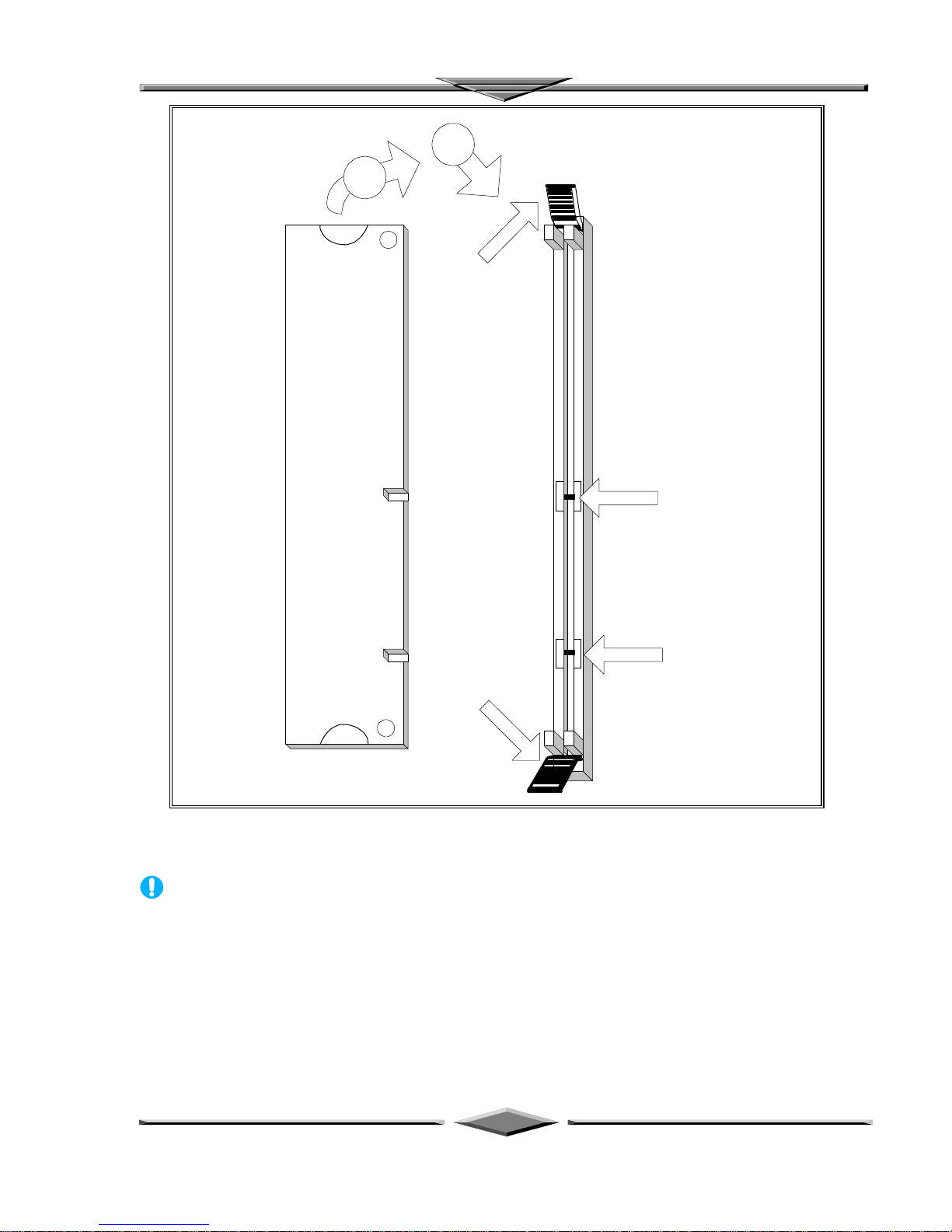
INSTALLING SYSTEM MEMORY (RAM)................................................................................................5
EXPANSION CARDS INSTALLATION.....................................................................................................7
CONNECTING EXTERNAL CONNECTOR ..............................................................................................7
AT Power Connector................................................................................................................................7
ATX Power Connector .............................................................................................................................8
Floppy Drive Connector ...........................................................................................................................8
IDE Connectors........................................................................................................................................8
Front Panel Function Connectors..............................................................................................................9
REPLACING BATTERY........................................................................................................................... 10
QUICK INSTALLATION GUIDE..............................................................................................................11
“Auto Jumper Yes” Guide ......................................................................................................................13
“CPU Voltage Selection”........................................................................................................................ 13
QUICK REFERENCE OF YOUR MOTHERBOARD ...............................................................................................16
AMICMOS SETUP.....................................................................................................................................19
STANDARD CMOS SETUP............................................................................................................................20
CPU SETUP......................................................................................................................................................22
ADVANCED CMOS SETUP...........................................................................................................................23
ADVANCED CHIPSET SETUP .....................................................................................................................26
PCI/PNP SETUP.............................................................................................................................................28
POWER MANAGEMENT SETUP............................................................................................................32
PERIPHERAL SETUP................................................................................................................................34
MOTHERBOARD TECHNICAL SPECIFICATION................................................................................37
ENVIRONMENT ......................................................................................................................................37
DIMENSIONS AND WEIGHT.................................................................................................................. 37
ELECTRICAL SPECIFICATION.............................................................................................................. 37
POWER CONSUMPTION......................................................................................................................... 37
REQUEST FOR TECHNICAL SUPPORT................................................................................................38

Motherboard Installation
Page 1
Features of the Board
Overview
Congratulations on purchasing the highest performance Pentium®motherboard. With the advanced
technology available today, this motherboard is designed to run Intel’s Pentium processors at speeds up
to 233 MHz. The on-board system memory consists of SIMM and DIMM giving you the most flexibility
for system design. It supports up to 128 MB of DRAM using standard 72-pin SIMM sockets that accept
either Fast Page Mode (FPM), Extended Data Out (EDO) memory. In addition, two unbuffered, 3.3 Volts,
168-pin SDRAM sockets are also included for 16 to 256MB synchronous Dynamic memory support. A
321-pins type 7, Zero Insertion Force (ZIF) socket allows an easy upgrade path for the future Pentium
Overdrive®processors.
The motherboard uses VIA VT82580VPX PCI chipset. The VIA VT82C586B PCI/ISA Bridge provides
an integrated Bus Mastering IDE controller with two high performance UltraDMA-33 EIDE interfaces for
up to four IDE devices (such as hard drives or CD-ROM). The PCI/ISA Bridge also including an USB
interface. The integrated I/O controller integrates the standard PC I/O functions: floppy interface, two
FIFO serial ports, one EPP/ECP capable parallel port, and support for an IrDA and Consumer Infra Red
compatible interface.
Four on-board 32-bit PCI local bus slots allow a higher bandwidth data path, which serves as a super
highway for intensive data-movement such as video or networking. The BIOS support PCI bridge user
configuration, which allows further expansion of the system with PCI peripherals. Up to two 16-bit ISA
slots are provided so that the board is backward hardware compatible with the older expansion card. A
total of five expansion slots can be populated with add-in cards as one PCI and ISA slots share the same
chassis I/O panel. Two full lengths ISA add-in cards can be installed while the third can be half-length.
All PCI cards can be full lengths.
Auto Jumper Yes
This motherboard is one of our “Auto Jumper Yes” series, which eliminates the necessity for the user to be
bored by jumper settings on the motherboard. It is capable of detecting the CPU brand, and setting the
appropriate CPU core voltage and speed according to instructions from the user through CMOS setup
menu. In contrast to “Jumperless”, “Auto Jumper Yes” allows switching to manual mode that enables
physical jumpers on the mainboard, so as to prevents the potential impacts on jumperless boards from the
future CPU specifications. On the other hand, pressing “F” to clear CMOS setting and “J” to re-detect
CPU during power on the system, to avoid the difficulties to reset the CMOS data.
Features Summary
This motherboard comes with following features:
þSupports Intel Pentium®Processor up to 233MHz, which included the newest MMX CPU.
þVIA VPX PCIset, including a 82C585VPX PCI/Memory controller , 82C587 data bus Accelerator
and 82C586B PCI ISA IDE Accelerator.
þWith a On-Board Crystal™ 3D Sound Chip.
þWAKEUP-LINK interface header supporting Intel Wake-On-LAN
þTA-LINK interface headers supporting E100+ PCI LAN Card using the Intel™ LAN chip.

Motherboard Installation
Page 2
þSupports “Modems Ring On” (Requires ATX power supply and External COM2)
þPnP BIOS with support for power management, UltraDMA33/EIDE/SCSI features and desktop
management interface (DMI) which allows higher level of hardware compatibility.
þFlash BIOS for easy upgrade
þUp to 2 each 72-pin SIMM sockets, supports up to 128 MB DRAM in two banks, which included
FPM, EDO DRAM types
þThe total of two high speed unbuffered SDRAM sockets, supports 16-256M memory.
þTwo 16-bit ISA expansion slots and four 32-bit PCI expansion slots.
þIntegrated two PCI bus master UltraDMA-33 EIDE controller with two on-board connectors supports
up to four IDE devices such as Hard Disk, CD-ROM or Tape Backup drives. USB interface also
provided.
þIntegrated I/O chipset featuring one floppy disk controller, two 16550 UART compatible serial ports,
one high speed EPP/ECP capable parallel port, one Infra Red port.

Motherboard Installation
Page 3
Motherboard Installation
INSTALLATION PRECAUTIONS
During installation and initial test, use caution to avoid personal injury and damage to wiring due to sharp
pins on connectors and printed circuit assemblies, rough chassis edges and corners, and hot components.
Adhere to warnings and limitations regarding accessibility into areas designated only for authorized
technical personnel.
A QUICK INTRODUCTION
To Install and operate your the new motherboard, you must follow the steps below:
1. Set Jumpers on the motherboard
2. Install the CPU with cooling fan
3. Install RAM modules
4. Connect cables, wires and power connector
5. Install expansion cards
Jumpers Setting
There are several user-adjustable jumpers on the board which allow you to configure your system to match
your requirements. This chapter contains the information on the various jumpers settings and connector
on your motherboard.
Jumpers
Jumpers are used to make several hardware settings on the motherboard. From the “Map of the
Motherboard” shown above, you can identify the location of the jumpers. There are two kinds of jumper
on-board, 2-pin jumper and 3-pin jumper. On the symbol of jumper likes “ ”, “ ” inside stands
for pin 1. To set a jumper, a black cap containing metal contacts is placed across the jumper pin/s
according to your required configuration. The jumper settings will also be described numerically such as
[open] for open, [short] for short, [1-2] for connect pins 1&2, [2-3] for connects pins 2&3 respectively.
Black cap
Onboard
jumper
Pin 1 symbol on
the silk screen
Pin 1 Pin 3Pin 2
CAUTION
performance.

Motherboard Installation
Page 4
CPU Installation
The motherboard provides a 321-pins, type-7, ZIP socket. The CPU should have a fan attached to it to
prevent overheating. If this is not the case then purchase a fan before you turn-on the system.
1
90
Socket 7
Intel
Pentium
2
45 degree Index
corner
CPU
COOLING
FAN
+12V (Red)
Ground (Black)
CPU Installation Diagram
CAUTION
Without a effective cooling fan, the CPU can overheat and cause damage to both the CPU
and the motherboard.

Motherboard Installation
Page 5
INSTALLING SYSTEM MEMORY (RAM)
The motherboard supports two 72-pin SIMMs (Single-In-Line Memory Modules) from 8MB up to 256MB
memory size and two 168-pin DIMM. The four 72-pin SIMMs sockets are divided into two memory
banks, Bank 0 and Bank 1, and each bank has two SIMM sockets which accept either FPM or EDO
DRAM module.
1
3
1
3
2
Push upward
to lock
45 degree
insert into
the socket
To remove the
SIMM/s, pull the
retaining latch on
both ends
Notched end towards
the Keyboard
connector side
Retaining latch
SIMM Module Installation Diagram
CAUTION
Each bank must have the same size and type of memory module installed in pairs.

Motherboard Installation
Page 6
3.3V Key
Unbuffered
DRAM Key
128 Bit 168 PIN DRAM DIMM
Push to remove
DIMM module
Push to remove
DIMM module
12
Vertically Insert
for Installation
168-Pin SDRAM Module Installation Diagram
CAUTION
SDRAM Module cannot be used together with the SIMMs Module.

Motherboard Installation
Page 7
EXPANSION CARDS INSTALLATION
At the most of beginning, you must read your expansion card documentation on any hardware and
software settings that may be required. The installation procedures are summarized as below:
1. Read the User’s Guide/Manual of your expansion card.
2. If necessary, set any jumpers on your expansion card.
3. Power-off the system and then disconnected the power cord.
4. Remove your computer’s cover.
5. Remove the metal bracket from one of the empty slot, ISA or PCI, corresponding to the type
of expansion card.
6. Carefully align the card’s connectors and press firmly, make sure that the connection is
good.
7. Secure the card on the slot.
8. Replace the computer’s cover.
9. Setup the BIOS configuration if necessary.
10. Install the required software drivers for your expansion card.
CAUTION
Before adding or removing any expansion card or other system components, make sure
that you unplug your system power supply. Failure to do so may cause damage of your
motherboard and expansion cards.
CONNECTING EXTERNAL CONNECTOR
AT Power Connector
A 12-Pin power supplies provide two plugs incorporates standard ±5V and ±12V, each containing six
wires, two of which are black. Orient the connectors so that the black wires are together.
Pin Signal Name Pin Signal Name
1Power Good Signal 7Ground
2+5V 8Ground
3+12V 9-5V
4-12V 10 +5V
5Ground 11 +5V
6Ground 12 +5V
Two 6-Pin Plugs
From AT Power Supply
Vertically Insert
For Installation
Place 2 Black Wires,
On Each Of The
Plug, Closed To The
Centre
AT Power Connector Installation

Motherboard Installation
Page 8
ATX Power Connector
A single 20-pin connector incorporates standard ±5V and ±12V, optional 3.3V and soft-power signals.
With a power supply supports remote power on/off, the motherboard can turn off the system power
through software control, such as the shutdown in Windows 95 Start menu. The system BIOS will turn
the system power off when it receives the proper APM command from the OS. APM must be enabled in
the system BIOS and OS in order for the soft-off feature to work correctly.
Pin Signal Name Pin Signal Name
1+3.3V 11 +3.3V
2+3.3V 12 -12V
3Ground 13 Ground
4+5V 14 PW_ON
5Ground 15 Ground
6+5V 16 Ground
7Ground 17 Ground
8PWRGOOD 18 -5V
9+5VSB 19 +5V
10 +12V 20 +5V
From ATX Regulated
Power Supply 6DXP Motherboard
ATX Power Connector Connector's Lock
(push to release)
PW1
Onboard receptacle
ATX Power Connector Installation
Floppy Drive Connector
This 34-pin connector supports the provided floppy drive ribbon cable. After connecting the single end to
the on-board “FLOPPY” connector, connect the remaining plugs on the other end to the floppy drives
correspondingly.
IDE Connectors
The two on-board IDE connectors support the provided 40-pin IDE hard disk ribbon cable. After
connecting the single end to the board, connect the two remaining plugs at the other end of your hard
disk(s). If you install two hard disks, you must configure the two drives by setting its jumpers according to
the documentation of your hard disk. Also, you may connect the two hard disks to be both Masters using
one ribbon cable on the primary IDE connector and one on the secondary IDE connector.

Motherboard Installation
Page 9
Red Wire Side
Pin 1 Side
Pin 1 Side
Provided 10 Pin
Ribbon cable
Provided 40 Pin
Ribbon cable
Ribbon cable Installation Example
NOTICE
For the flat ribbon cable connection, please make sure that the pin 1 of the ribbon cable
(the red wire side of the cable) is correctly connected to the on-board connector’s pin 1 as
shown on the “Map of the Motherboard”.
Front Panel Function Connectors
All the front panel indicator, speaker, and switch functions are grouped into a on-board 26-pin connector,
J5. Front panel features supported include:
•System Reset, RESET
•Power LED, form KEYLOCK
•Hard Drive activity LED, IDE LED
•System Speaker, SPEAKER
•Soft-touch button power on/off, SW ON
•External power saving control, EXTSMI (optional)
The connector pin out are described as the figure below:
KEY
LOCK
KEYLOCK
SPEAKER EXTSMI
PWBTRESET IDE LED
J5
13
26 14
GND
VCC SPKR
PW LED
GND GND
EXT
SMI
RST
GND
IDE
LED
GND
PUSH-ON
SBV
The Onboard Function Connector Pin Out

Motherboard Installation
Page 10
Integrated USB, Infra-Red and PS/2 Mouse connector
The total of two USB device connectors, a PS/2 mouse, and an Infrared devices are all allocated at this
connector (JP15).
•Pin1 to Pin5 for USB1 connector
•Pin11 to Pin15 for USB2 connector
•Pin6 to Pin10 for PS/2 connector
•Pin16 to Pin20 InfraRed connector
The connector pin out signal definitions are described as the table below:
Pin Signal Name Pin Signal Name
1 (USB1) USB +5 Volt 11 (USB2) USB +5 Volt
2USB Port 1- 12 USB Port 2-
3USB Port 1+ 13 USB Port 2+
4Ground 14 Ground
5No Connect 15 No Connect
6 (PS/2 Mouse) PS/2 Data 16 (IR) +5V
7PS/2 Clock 17 No Connect
8Ground 18 Infrared Receive
9No Connect 19 Ground
10 +5V 20 Infrared Transmit
On-board Sound Connector ( TX98-3D )
The total of three connectors are using to support the On-board sound features. JP18 including the Line-
In, Mic-In, Line-Out and MIDI/JOYSTICK. J6 and J7 are the CD-Audio input headers, and there pin out
signal definitions are described as the table below:
Header Pin1 Pin2 Pin3 Pin4
J6, J7 Ground Right Ground Left
REPLACING BATTERY
A 3V, CR-2030, Lithium battery is installed on the on-board battery socket. This battery is used to supply
the CMOS RAM backup power during system powered-off. Danger of explosion if battery is incorrectly
replaced. Therefore, if you have any difficulties, please consult to the technical personnel.
IR
USB 11
11 20USB 2
10
PS/2 Mouse

Motherboard Installation
Page 11
Quick Installation Guide
i
Socket 7
r
A
B
C
D
E
F
G
J
K
L
O
R
S
J5
H
I
T
M
Q
VID1
BF1
VID4
BF0
VID0
VID2
BF2
JP16
VID3
COM2
COM1
JP15
PRINTER
PRIMARY IDE
SECONDARY IDE
DIMM1
DIMM2
SIMM1
SIMM2
FLOPPY
AUDIO
JP18
FQ3
FQ2
FQ1
ISA2
ISA1
PCI4
PCI3
PCI1
PCI2
J7
J6
JP19
JP17
TA-LINK
WAKEUP-LINK
TX98-3D

Motherboard Installation
Page 12
TX98-3D
A. AT Power Supply Connector K. Audio CD Connectors
B. ATX Power Supply Connector L. PCI Bus Connector
C. AT Keyboard Connector M. ISA Bus Connectors
D. Serial (COM1 and 2) Headers
E. Parallel (Printer) Port Header O. Front Panel Connector
F. Integrated Functions Connector P. TC-LINK SCSI Header
G. 3.3v DIMM Sockets Q. WAKEUP-LINK Header
H. SIMM RAM Sockets R. TA-LINK Intel LAN Header
I. Floppy Drive Connector S. IDE Connectors
J. Audio Connector T. Pentium Socket 7

Motherboard Installation
Page 13
“Auto Jumper Yes” Guide
•To enable the “Auto Jumper Yes”, the onboard jumper JP16 must shorted (1-2). Then,
the CPU brands and its core voltage will automatically detected. But one thing to remind
is the CPU speed is necessary to select a suitable one at the CMOS setup. Or, if JP16 is
shorted (2-3), that means you should follow the jumper table (at the next page) to setup
your CPU settings manually. On the other hand, pressing the key “F” to clear the
CMOS setting and “J” to re-detect the CPU setting during power up your system.
“CPU Voltage Selection”
•The voltage regulator will automatically detect and switch between Single Power Plane
& Dual Power Planes.

Motherboard Installation
Page 14
INTEL PENTIUM P54C/P55C CPU
Internal CPU
Speed (MHz) External Bus
Speed (MHz) FQ3 FQ2 FQ1 Frequency
Ratio BF2 BF1 BF0
100 66 [1-2] [1-2] [1-2] 1.5x 1-2 1-2 1-2
120 60 [1-2] [1-2] [2-3] 2.0x 1-2 1-2 2-3
133 66 [1-2] [1-2] [1-2] 2.0x 1-2 1-2 2-3
150 60 [1-2] [1-2] [2-3] 2.5x 1-2 2-3 2-3
166 66 [1-2] [1-2] [1-2] 2.5x 1-2 2-3 2-3
200 66 [1-2] [1-2] [1-2] 3.0x 1-2 2-3 1-2
233 66 [1-2] [1-2] [1-2] 3.5x 1-2 1-2 1-2
CYRIX/IBM 6x86 M1/M2 CPU
P150+ 60 [1-2] [1-2] [2-3] 2.0x 1-2 1-2 2-3
P166+ 66 [1-2] [1-2] [1-2] 2.0x 1-2 1-2 2-3
PR200 75 [1-2] [2-3] [1-2] 2.0x 1-2 1-2 2-3
PR233 66 [1-2] [1-2] [1-2] 3.0x 1-2 2-3 1-2
PR233 75 [1-2] [2-3] [1-2] 2.5x 1-2 2-3 2-3
PR266 66 [1-2] [1-2] [1-2] 3.5x 1-2 1-2 1-2
PR300 66 [1-2] [1-2] [1-2] 3.5x 1-2 1-2 1-2
PR300 75 [1-2] [2-3] [1-2] 3.0x 1-2 2-3 1-2
PR333 75 [1-2] [2-3] [1-2] 3.5x 1-2 1-2 1-2
PR333 83 [2-3] [1-2] [2-3] 3.0x 1-2 2-3 1-2
AMD-K5/K6 CPU
PR100 66 [1-2] [1-2] [1-2] 1.5x 1-2 1-2 1-2
PR166/K6-166 66 [1-2] [1-2] [1-2] 2.5x 1-2 2-3 2-3
PR200 66 [1-2] [1-2] [1-2] 3.0x 1-2 2-3 1-2
PR233 66 [1-2] [1-2] [1-2] 3.5x 1-2 1-2 1-2
PR266 66 [1-2] [1-2] [1-2] 4.0x 2-3 1-2 2-3
PR300 66 [1-2] [1-2] [1-2] 4.5x 2-3 2-3 2-3
PR333 66 [1-2] [1-2] [1-2] 5.0x 2-3 2-3 1-2
IDT-C6
150 50 [2-3] [2-3] [2-3] 3.0x 1-2 2-3 1-2
150 75 [1-2] [2-3] [1-2] 2.0x 1-2 1-2 2-3
180 60 [1-2] [1-2] [2-3] 3.0x 1-2 2-3 1-2
200 66 [1-2] [1-2] [1-2] 3.0x 1-2 2-3 1-2
225 75 [1-2] [2-3] [1-2] 3.0x 1-2 2-3 1-2
CPU Voltage Selection
CPU type Voltage Requirements
Intel Pentium P54C, Cyrix/IBM M1 6x86, AMD-K5,IDT-
C6 3.4V (STD) / 3.5V (VRE)
Intel Pentium P55C, Cyrix/IBM M1 6x86L
Cyrix/IBM 6x86MX, MII, K6-PR166/200
AMD-K6-PR233
AMD-K6-PR266, PR300
2.8V
2.9V
3.2V
2.2V

Motherboard Installation
Page 15

Motherboard Installation
Page 16
CPU Core Voltage Table Bus Frequency Ratio
Vcore VID4 VID3 VID2 VID1 VID0 Ratio BF2 BF1 BF0
2.2V 1-2 1-2 1-2 2-3 1-2 2.0x 1-2 1-2 2-3
2.8V 1-2 2-3 1-2 1-2 1-2 2.5x 1-2 2-3 2-3
2.9V 1-2 2-3 1-2 1-2 2-3 3.0x 1-2 2-3 1-2
3.2V 1-2 2-3 2-3 1-2 1-2 3.5x / 1.5x 1-2 1-2 1-2
3.3V 1-2 2-3 2-3 1-2 2-3 4.0x 2-3 1-2 2-3
3.4V 1-2 2-3 2-3 2-3 1-2 4.5x 2-3 2-3 2-3
3.5V 1-2 2-3 2-3 2-3 2-3 5.0x 2-3 2-3 1-2
5.5x 2-3 1-2 1-2

Motherboard Installation
Page 17
Quick Reference of Your Motherboard
[A] AT Power Supply Connector
Based on the AT specification, one 12-pin power connector covers all the required power sources, ±5V
and ±12V.
[B] ATX Power Supply Connector
Based on the ATX specifications, one 20-pin power connector covers all the required power sources, ±5V,
±12V, and ±3.3V, with soft-touch button power on/off features. This connector reduces the installation
time and minimizes the chance of defects caused by incorrect connection.
[C] AT Keyboard Connector
This connection is used for a standard IBM-compatible keyboard, such as 101 enhanced keyboard.
[D] Serial (COM 1 and 2) Port Headers
This motherboard provides two high-speed UART compatible serial ports.
[E] Parallel (Printer) Port Connector
One Parallel port with SPP, EPP and ECP capabilities.
[F] Integrated Functions Connector
I) From Pin1 to Pin5 is the first USB device “USB1” and Pin11 to Pin15 is the second USB device
“USB2” connector. Universal Serial Bus (USB) is new interface standard for any I/O device
“Outside the Box”. USB makes your peripherals have a real plug and play (PnP) capabilities with
up to 12MB/sec data speed In the coming soon, any external device connected to your computer
will be standardized into USB standard which are all have a special 4-pin rectangle shape
connector. Therefore, with the Intel chipset, this motherboard builds two USB headers on-board
for you future investment. If you are using an USB device, you must purchase an optional USB
connector.
II) From Pin6-10 is the PS/2 device, likes some PS/2 keyboard and mouse, are all have a standard 6-
pin round shape connector. However, it does not have a unique onboard standard. Therefore,
please refer to the Chapter “Motherboard Installation”, in order to purchase an suitable PS/2
Mouse Connector.
III) From Pin16-20 is a 5-pin interface on the front panel I/O connector is provided to allow
connection to a Hewlett Packard HSDSL-1000 compatible Infra-red (IrDA) transmitter/receiver.
Once the module is connected to the front panel I/O header, Serial port 2 can be re-directed to the
IrDA module. When configured for IrDA, the user can transfer files to or from portable devices
such as laptops, PDA’s and printers using application software such as LapLink. The IrDA
specification provides for data transfers at 115kbps from a distance of 1 meter. Support for
Consumer Infra Red (ASK-IR) is also included, please refer to your IR equipment for more
detailed information.
[G] SDRAM Socket
There are two unbuffered, 3.3 Volts, SDRAM socket on-board provides more flexibility for your system
memory upgrade.
Table of contents
Other Zida Motherboard manuals
Popular Motherboard manuals by other brands

Gigabyte
Gigabyte 6VX7-4X user manual

ASROCK
ASROCK 775XFIRE-ESATA2 - 02-2006 Guide to installation and Configuration

Linear Technology
Linear Technology DC1989A-C Demo Manual

Linear Technology
Linear Technology DC2117A Demo Manual

Linear Technology
Linear Technology DC1696 Demo Manual

Analog Devices
Analog Devices DC2875A Demo Manual