L-BAL-E185-GB 1902 Index 004 ZNo. 11660-0711-02
9/12
13. Safety instructions and references for putting into operation
- please read carefully!
Special remarks for hazardous areas (Zone 0, Zone 1 and Zone 2)
•The increased danger within hazardous areas requires the careful attention of the
safety instructions and references for putting into operation. Observe the national safety
rules and regulations for prevention of accidents as well as the European standard EN
60079-14 „Electrical apparatus for explosive gas atmospheres - Part 14: Electrical
installations in hazardous areas (other than mines)”. All work for the connection, for
putting into operation and maintenance is to be implemented by qualified, responsible
technical personnel. Inappropriate behaviour can cause heavy personal damage and
damages to property.
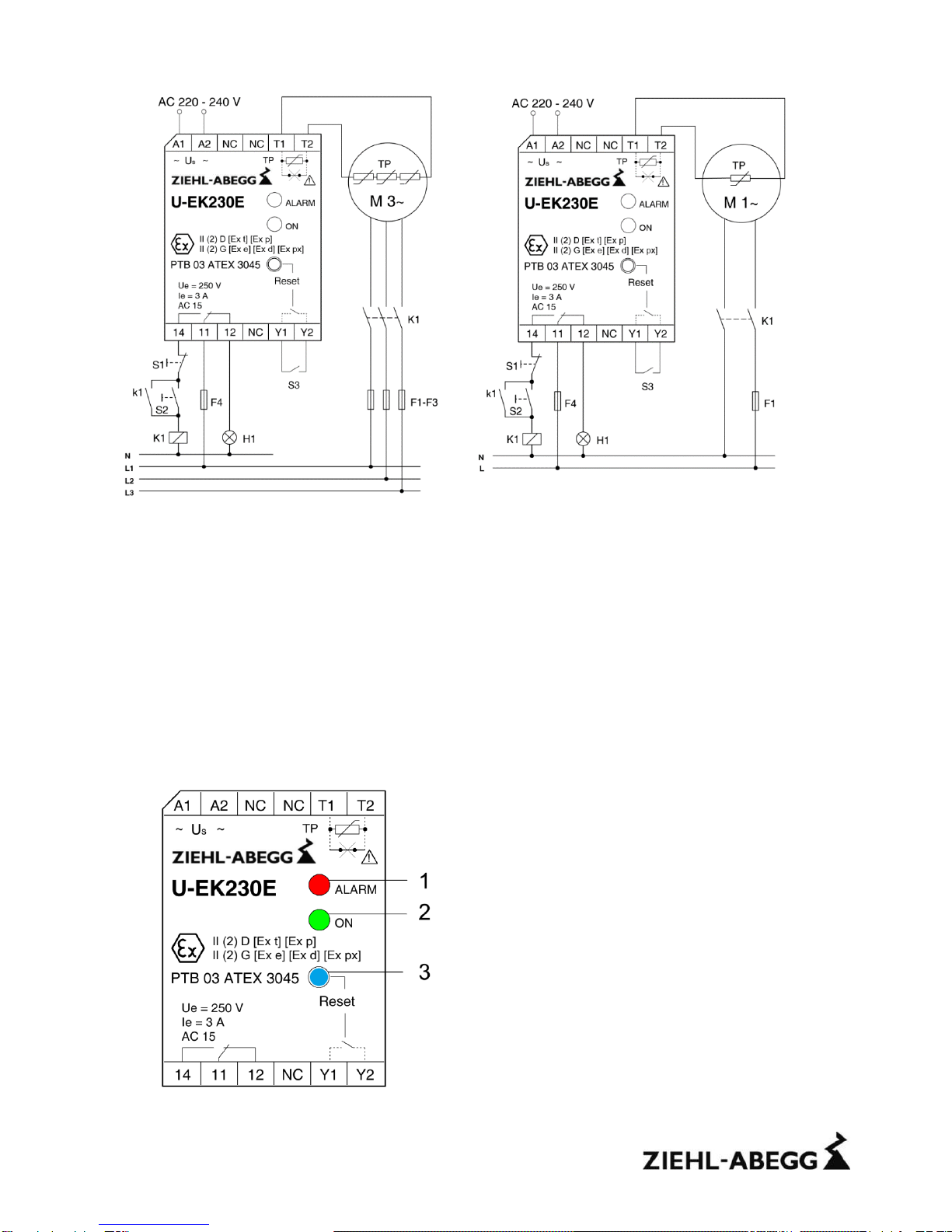
•The response of the thermal motor protection must directly switch off the motor, also
when used together with frequency inverters. This must be realized in the logic section
or configuration in the inverter.
•The tripping device may be installed only outside potentially explosive atmospheres for
the protection of explosive-protected motors. When used in potentially atmospheres, the
device must comply with the required type of protection.
Special remarks for use in the presence of combustible dust (Zone 20, Zone 21 and
Zone 22)
•The increased danger within hazardous areas of combustible dust requires the careful
attention of the safety instructions and references for putting into operation. Observe the
national safety rules and regulations for prevention of accidents as well as the European
Standard EN 61241-14 „Electrical apparatus for use in the presence of combustible dust
–Part 14: Selection and installation”(new in EN 60079-14). Installation, electrical
connection and commissioning to be carried out by trained service personnel only.
Inappropriate behaviour can cause heavy personal damage and damages to property.
•The relay may be installed only outside potentially explosive atmospheres for the
protection of explosive-protected motors. Within potentially explosive atmospheres the
equipment is to be provided with a dust proofed enclosure according EN 60529.
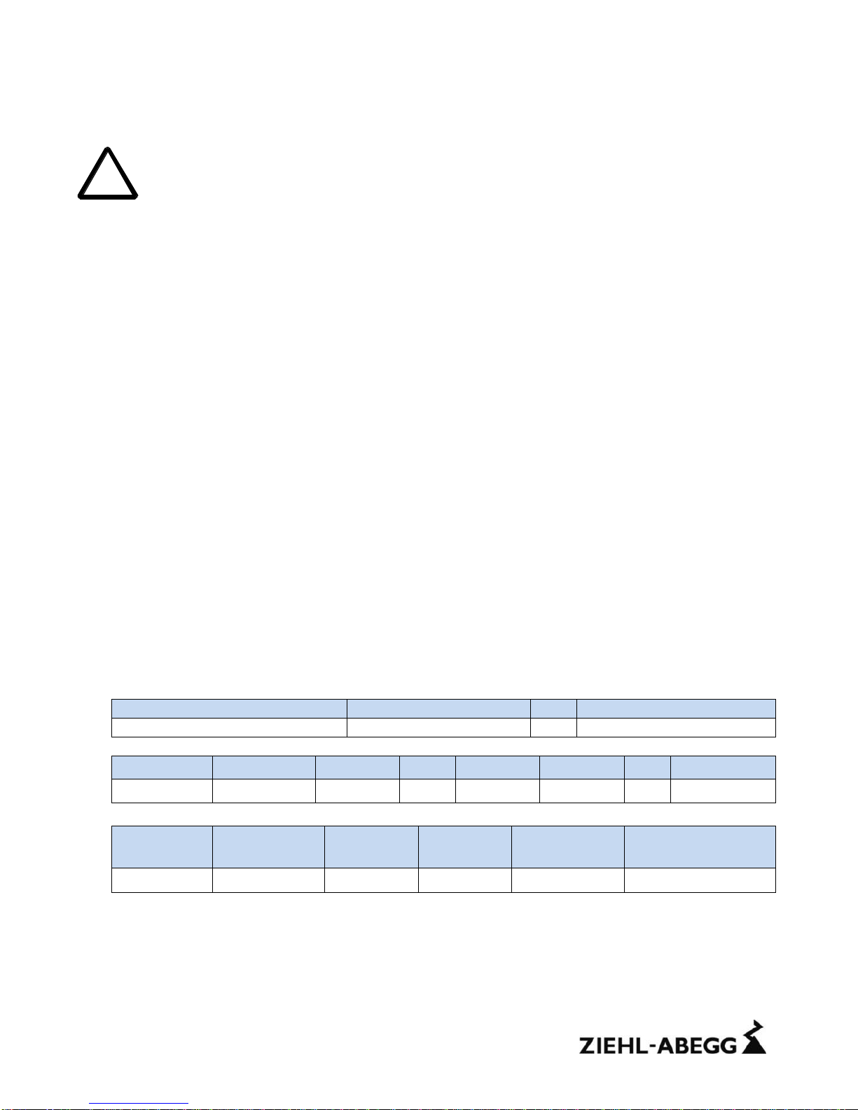
14. Safety characteristics of the safety device
Safety Integrity Level (EN 61508) and safety related parameters