Climate Controller KST-20 Vento | KST-20 Vento/CO2 | KST-20 Vento/RN
Handbook Version: ENG_05052020_ANHU_KST20VENTO| 3
Index
1. scope of delivery ................................... 3
2. General notes ........................................ 3
2.1. installation personnel ............................ 4
2.2. Used Pictograms.................................... 4
2.3. Intended use.......................................... 4
2.4. Foreseeable misuse ............................... 4
2.5. Safety Instructions................................. 4
3. product description ............................... 5
3.1. Technical specifications ......................... 5
3.2. Standards and Regulations .................... 5
3.3. aH-Controlled Technology ..................... 5
3.4. Operating modes................................... 5
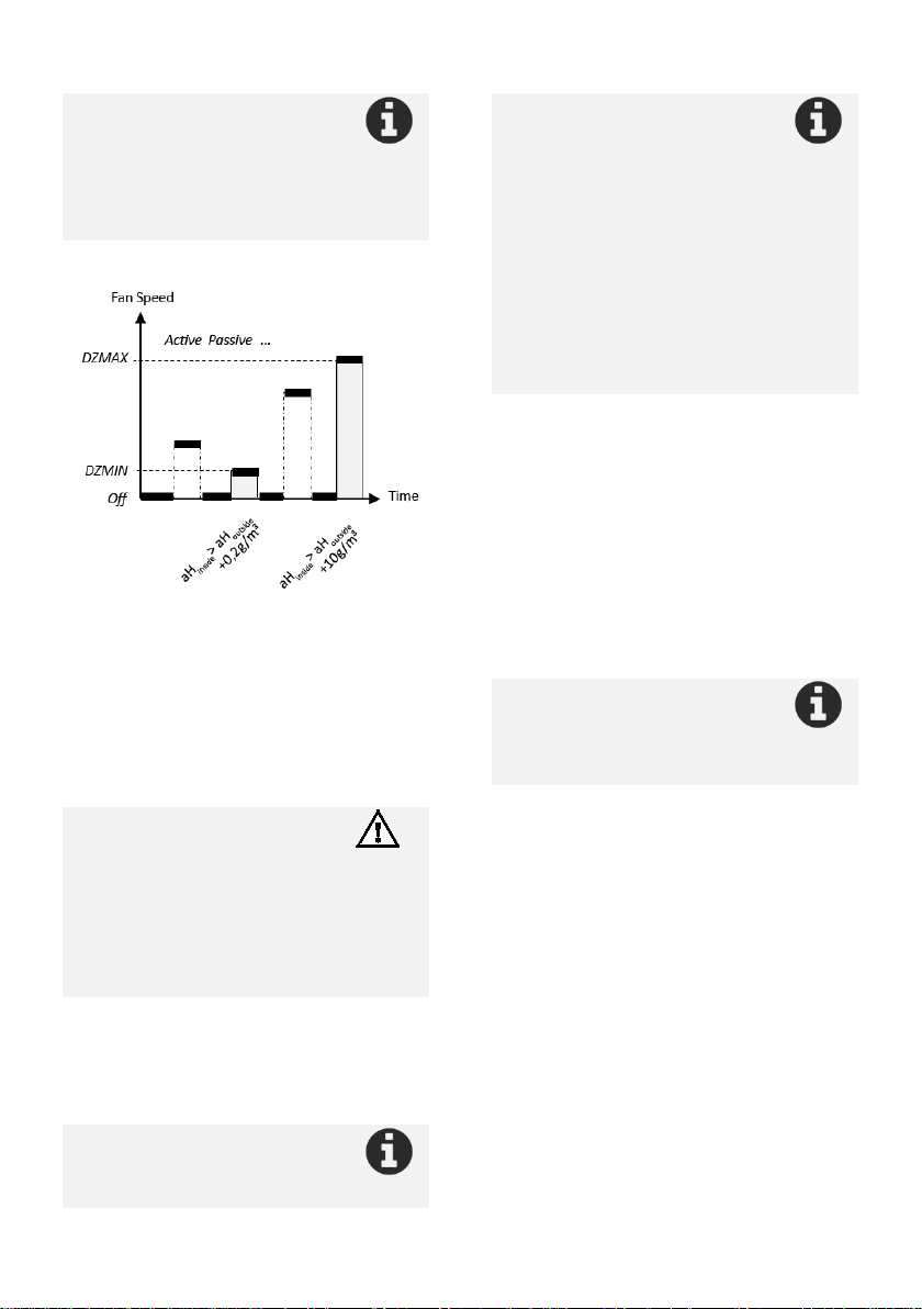
3.4.1. Dehumidifying (E) ....................... 5
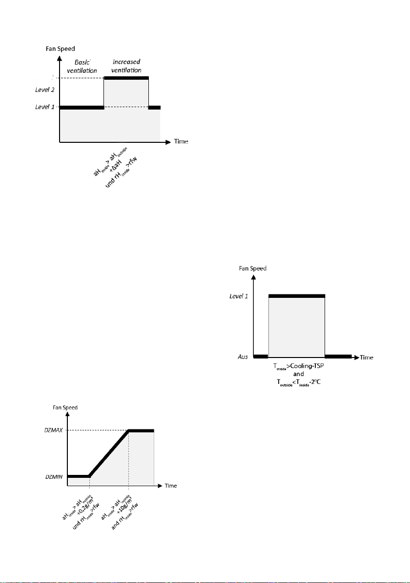
3.4.2. Ventilation (L) ............................. 7
3.4.3. Cooling (K) .................................. 8
3.5. Comfort functions ................................. 9
4. assembly and commissioning ................ 9
5. connection of the actuators ................ 11
5.1. Control electronics .............................. 11
5.2. Connection variants............................. 12
6. device functions .................................. 12
6.1. Factory settings ................................... 12
6.2. Display illumination ............................. 13
6.3. Functions of the keys........................... 13
6.4. Menu navigation and configuration .... 13
6.4.1. operating mode ........................ 14
6.4.2. actuators................................... 14
6.4.3. antifreeze temperature (FS) ..... 15
6.4.4. Timer (Suhr).............................. 15
6.4.5. dry protection (TS).................... 15
6.4.6. Time.......................................... 15
6.4.7. Date .......................................... 15
6.4.8. target moisture ......................... 15
6.4.9. Delta aH .................................... 15
6.4.10. Cool -TSP................................... 16
6.4.11. Speed Min/Max ........................ 16
6.4.12. LEDs .......................................... 16
6.4.13. Error indication on the display.. 16
7. circuit diagrams ................................... 16
8. additions to the KST-20 Vento/CO2..... 18
8.1. actuators ............................................. 18
8.2. CO2- Measurement ............................. 18
8.3. Connection of the sensors ................... 18
9. additions to the KST-20 Vento /RN...... 19
9.1. actuators ............................................. 19
9.2. Radon measurement ........................... 19
9.3. Connection of the sensors ................... 19
10.device support..................................... 20
1. scope of delivery
•Climate Control KST-20 Vento
•Power cable
•Climate sensor inside (integrated or
detached)
•Climate sensor outside (detached, max. 10m
cable)
•mounting and operating instructions
•2-pole plug (terminal 5)
•Wall mounting set
Components for device version RN or CO2
•Radon sensor (KST-20 Vento/RN)
•CO2-Sensor, integrated or detached (KST-20
Vento/CO2
2. General notes
•Read safety instructions and keep the manual
•Installation, commissioning, electrical
connection and repairs of the KST-20 Vento
are only permitted by qualified persons.
•The specified protection class is only
guaranteed if the cables are installed in the
correct position and correctly inserted and
connected.
•Only operate the device at the specified
voltage
•Modification and conversion of the device is
not permitted and releases ZILA GmbH from
any warranty and liability
Please read these installation
instructions carefully before using
the KST-
20 Vento air conditioning
control unit. Follow the instructions.
Keep these installation instructions in
a safe place for future use.