manuals.online logo
Brands
  1. Home
  2. •
  3. Brands
  4. •
  5. Gira
  6. •
  7. Controllers
  8. •
  9. Gira 0566 Series User manual

Gira 0566 Series User manual

GIRA
Info Instabus Continuous Controller
Installation Instructions
Powernet Continuous Controller 19/99 Page: 1 of 3
Instabus Continuous Controller Order No.: 0566 ..
System Information
This device is a product of the Instabus EIB-system and complies with EIBA directives. Detailed
technical knowledge obtained in Instabus training courses is a prerequisite to proper understanding.
The functionality of this device depends upon the software. Detailed information on loadable software
and attainable functionality may be taken from the manufacturer’s product database.
Planning, installation and commissioning of the unit is done by means of EIBA certified software.
Function
The Instabus EIB continuous controller can be used for single-room temperature control. A continuous
control signal for directly triggering an Instabus actuating drive, for example, or a switching corrective
signal for triggering a dual 6 A Instabus switching actuator in connection with an electrothermic
actuating drive is alternatively possible.
Properties
Depending upon the setting, PI control, P control, two-position control or pulse width modulation PWM
•Heating and / or cooling with manual or automatic change-over and common or separate control
outputs are possible
•Two-stage heating or cooling operation
•Five different operating conditions with their individual set values
•Comfort mode continuation or change of mode by presence push-button
•Variable frost and heat protection
•Externally triggerable objects for presence push-button, automatic timer, door / window contact
and controller locking
•Acting-sense change-over via Instabus EIB
•Controller status as well as set and actual values are accessible through Instabus EIB
•Five LEDs to indicate the operating states
•Malfunction indication by mode LED
•Set value shifting by a maximum of ± 10 K possible by control knob and software
•Locking the controls for protection against unauthorised use possible
•Temperature alignment for Powernet applications.
GIRA
Info Instabus Continuous Controller
Installation Instructions
Powernet Continuous Controller 19/99 Page: 2 of 3
B
A
C
D
E
FGH
Controls and indicators
(please refer to opposite drawing)
A: Control knob for set value shifting by ± 10 K
max.
(Offset for standby and comfort temperatures
can be parameterised by software.)
B: Setting rings to limit the set value shift
(in the control knob).
C: Presence push-button to continue comfort
mode or to change the mode.
D: Yellow LED to indicate controller locking
(e. g. for dew point alarm).
E: Red LED to indicate frost / heat protection
mode.
F: Green LED to indicate comfort mode.
G: Green LED to indicate standby mode.
H: Green LED to indicate night operation.
Installation
Do not install this device within the range of heat sources. Plug the temperature controller onto a flush-
mounted bus coupler and install it into a standard flush-mounted box.
Contacting is established via the user interface.
For installation, pull off the control knob, plug the temperature controller onto the bus coupler and
secure it with the safety screw (protection against detaching). Return the control knob.
Warning
Caution: The installation and assembly of electrical equipment may only be performed by a
skilled electrician.
Subject to technical modifications.
Please hand this instructions leaflet to your customer after installation.
GIRA
Info Instabus Continuous Controller
Installation Instructions
Powernet Continuous Controller 19/99 Page: 3 of 3
Specifications
Supply
Instabus EIB: 24 V DC (+6/-4 V) through bus coupler (BC)
Power consumption
Instabus EIB: 150 mW max.
Connection
Instabus: Connecting and branch terminal
User interface: to be plugged onto BC (2 x 5-pole edge connector)
Basic stage control: Alternative continuous (PI control) or switching control signal
(PWM or two-position control)
Additional stage control: Alternative continuous (P control) or switching control signal
(PWM or two-position control)
Measuring range: 0 to 40 °C
Atmospheric humidity: 0 to 95 % (no condensation)
Resolution: ± 0.08 K
Set value
Comfort temperature: adjustabe from 7 to 40°C
Set value shift: ± 10 K max., continuous
Ambient temperature: -5 °C to +45 °C
Storage temperature: -25 °C to +70 °C
Protective system: IP 20
Protection class: III
Acceptance of guarantee
We accept the guarantee in accordance with the corresponding legal provisions.
Please return the unit postage paid to our central service department giving a brief description
of the fault:
Gira
Giersiepen GmbH & Co. KG
Service Center
Dahlienstrasse 12
D-42477 Radevormwald
The CE sign is a free trade sign addressed exclusively to the authorities and does not include
any warranty of any properties.
Gira
Giersiepen GmbH & Co. KG
Postfach 1220
D-42461 Radevormwald
Telefon: +49 / 21 95 / 602 - 0
Telefax: +49 / 21 95 / 602 - 339
Internet: www.gira.de

Other Gira Controllers manuals

Gira One 5061 00 User manual

Gira

Gira One 5061 00 User manual

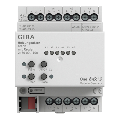
Gira KNX 2139 00 Operator's manual

Gira

Gira KNX 2139 00 Operator's manual

Gira 1289 00 User manual

Gira

Gira 1289 00 User manual

Gira 1288 Series User manual

Gira

Gira 1288 Series User manual

Gira 5431 00 User manual

Gira

Gira 5431 00 User manual

Gira System 3000 User manual

Gira

Gira System 3000 User manual

Gira One User manual

Gira

Gira One User manual

Gira 0309 00 User manual

Gira

Gira 0309 00 User manual

Gira KNX 5061 00 User manual

Gira

Gira KNX 5061 00 User manual

Gira 2100 Series User manual

Gira

Gira 2100 Series User manual

Gira System 3000 User manual

Gira

Gira System 3000 User manual

Gira KNX 213900 User manual

Gira

Gira KNX 213900 User manual

Gira 5023 00 User manual

Gira

Gira 5023 00 User manual

Gira 5423 00 User manual

Gira

Gira 5423 00 User manual

Gira 1039 00 User manual

Gira

Gira 1039 00 User manual

Gira 2114 00 User manual

Gira

Gira 2114 00 User manual

Gira 0570 00 User manual

Gira

Gira 0570 00 User manual

Gira 2164 00 User manual

Gira

Gira 2164 00 User manual

Gira One 5065 00 User manual

Gira

Gira One 5065 00 User manual

Gira 0425 00 User manual

Gira

Gira 0425 00 User manual

Gira 2100 Series User manual

Gira

Gira 2100 Series User manual

Gira One 5023 00 User manual

Gira

Gira One 5023 00 User manual

Gira One 5062 00 User manual

Gira

Gira One 5062 00 User manual

Gira 0399 00 User manual

Gira

Gira 0399 00 User manual

Popular Controllers manuals by other brands

Galaxy Control Systems 635 Series Worksheet

Galaxy Control Systems

Galaxy Control Systems 635 Series Worksheet

Wachendorff URDR001A user manual

Wachendorff

Wachendorff URDR001A user manual

Omega CNI16D user manual

Omega

Omega CNI16D user manual

Eurotherm Invensys 2408 Installation and operating handbook

Eurotherm

Eurotherm Invensys 2408 Installation and operating handbook

Walchem WBL400 Series instruction manual

Walchem

Walchem WBL400 Series instruction manual

Nordson Vantage Customer product manual

Nordson

Nordson Vantage Customer product manual

proSmart PS Plug user manual

proSmart

proSmart PS Plug user manual

Digitrax UT6 Series manual

Digitrax

Digitrax UT6 Series manual

tbs electronics Omnicharge Solar OCS 100-20 installation manual

tbs electronics

tbs electronics Omnicharge Solar OCS 100-20 installation manual

Allen-Bradley Logix5000 Series Programming manual

Allen-Bradley

Allen-Bradley Logix5000 Series Programming manual

MotoSAT J1 User and installation manual

MotoSAT

MotoSAT J1 User and installation manual

FunkTronic Major BOS 4a manual

FunkTronic

FunkTronic Major BOS 4a manual

Elegoo Mega2560 manual

Elegoo

Elegoo Mega2560 manual

Sanhua EEV SEC61 SERIES quick start guide

Sanhua

Sanhua EEV SEC61 SERIES quick start guide

Allen-Bradley MicroLogix 1200 Reference manual

Allen-Bradley

Allen-Bradley MicroLogix 1200 Reference manual

4IPNET WHG801 Quick installation guide

4IPNET

4IPNET WHG801 Quick installation guide

YASKAWA Motoman MLX200 HARDWARE INSTALLATION & SOFTWARE UPGRADE

YASKAWA

YASKAWA Motoman MLX200 HARDWARE INSTALLATION & SOFTWARE UPGRADE

frako EML 1101 manual

frako

frako EML 1101 manual

manuals.online logo
manuals.online logoBrands
  • About & Mission
  • Contact us
  • Privacy Policy
  • Terms and Conditions

Copyright 2025 Manuals.Online. All Rights Reserved.