Zing PB5500 User manual

Please ensure the Assembly Manual stays with the unit at all times.
Assembly Manual
PB5500 Zing MPS Gas Spring Lift, PB5504 Zing MPS Pow’r Up Lift
PB5502 Zing Supine Gas Spring Lift, PB5506 Zing Supine Pow’r Up Lift
PB5562 Zing MPS Tilt Table Gas Spring Lift, PB5566 Zing MPS Tilt Table Pow’r Up Lift
PB5564 Zing Supine Tilt Table Gas Spring Lift, PB5568 Zing Supine Tilt Table Pow’r Up Lift
PB5606 Zing Prone Gas Spring Lift, PB5608 Zing Prone Pow’r Up Lift
Size 2
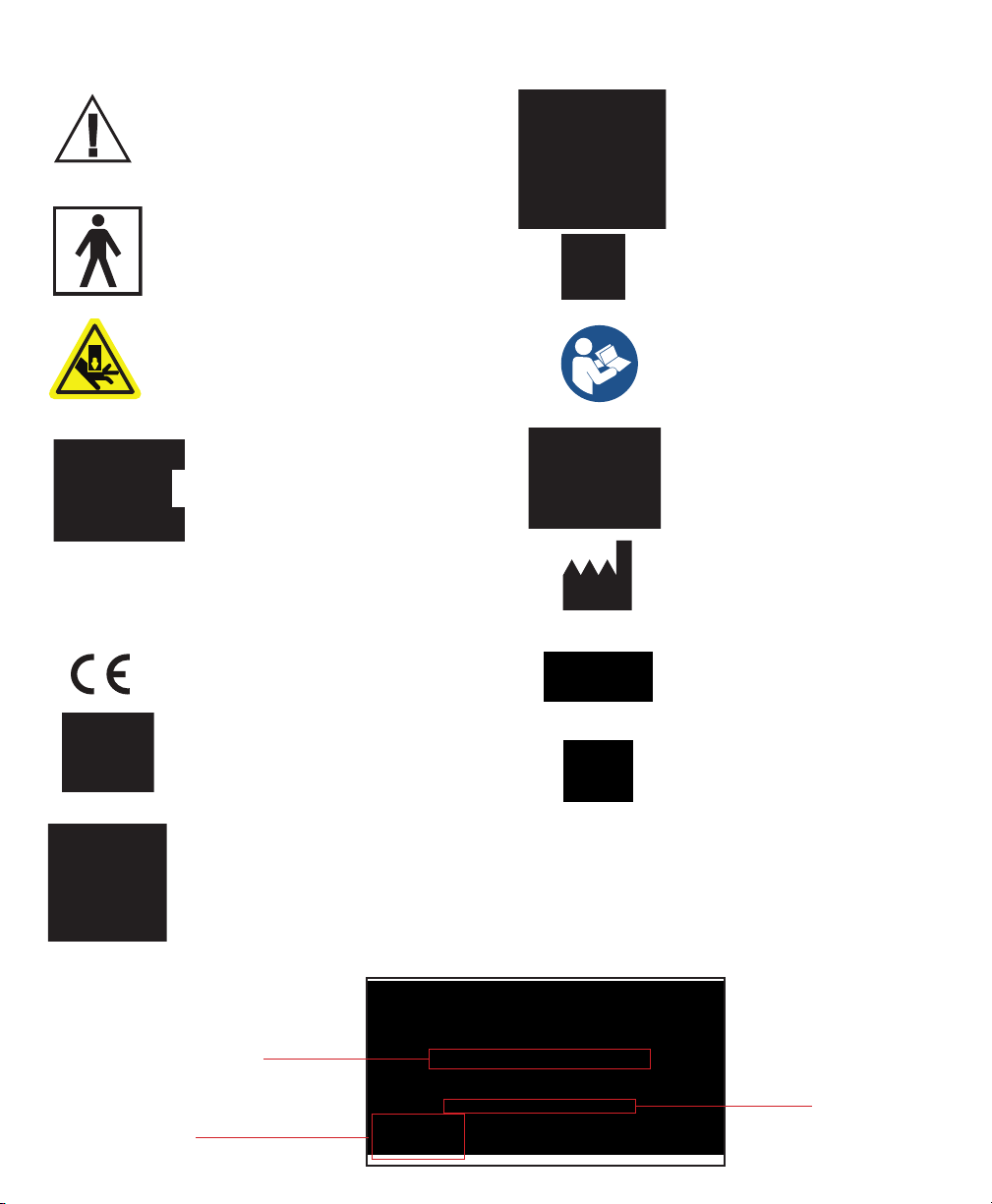
SYMBOL/LABEL LEGEND
CAUTION/WARNING/ATTENTION
PINCHPOINT
SERIAL NUMBER
SN
TEMPERATURE
DATE OF MANUFACTURE
Waste of electrical and electronic equipment must not be disposed as unsorted municipal waste. It must be
collected separately, and must be disposed as per local regulations. Contact your authorized representative
for information concerning the decommissioning of your equipment.
SEE INSTRUCTIONS FOR USE
TYPE BF APPLIED PART
MANUFACTURER
HUMIDITY ATMOSPHERIC PRESSURE
MEDICAL DEVICE
CONFORMITÈ EUROPËENNE PRESCRIPTION ONLY
POTENTIALLY HOT SURFACE
Accessible surfaces which may
exceed 105˚F/41˚C and could be a
hazard to persons with skin damage
or not having sensation.
CERTIFICATION LABEL/UNIQUE DEVICE IDENTIFICATION LABEL
Serial Number
Item Number
Item Description
Unique Identier

Table of Contents
Assembly . . . . . . . . . . . . . . . . . . . . . . . . . . . . . . . . . . . . . . 1
Parts Detail.................................... 20
Date Purchased Serial #
Serial number is located on the frame.
IMPORTANT
Zing Warranty Registration
FREE GIFT Upon Completion
(warranty & oer valid in the United States only)
To register online go to zingstanders.com/warranty
or Scan the
QR Code
IMPORTANT! Please complete and return within 30 days. To receive the free gift,
please ll out all information. Thank You.

Assembly
1. Remove everything from the box.
Remove all plastic wrap and parts from the
boxes.
2. Remove the bag of hardware from the
wheelbase. It contains the 4 bolts for the
mast assembly.
3. Position the mast as shown, place the
wheelbase as shown onto the mast.
Page 1
2
3

4B4A
5
6
Page 2
4A. Start all 4 bolts. Do not tighten at this
time.
4B. Once all 4 bolts have been started,
tighten them securely.
5. Remove the foot pedal and bolts from the
polly bag and place the foot pedal onto the
bottom of the gas spring as shown.
6. Line up holes and insert the 2 bolts, start
both bolts rst, then tighten securely.

9
7
8
7. Place unit onto its wheels as shown, and
lock casters.
8. If the Gas Spring Lockout was ordered,
unlock the gas spring by pulling the plunger.
(see page 33)
If the Gas Spring Lockout was not ordered,
remove the bolt from the lower part of the
cylinder on the mast as shown, discard bolt.
If the Pow’r Up Lift was ordered, plug the
battery and controller in.
9. Remove the nut, bolt and two washers
from the brace. These will be used in steps
10-15.
Page 3

10
Page 4
10. Flip up the brace as shown.
11. Depress the foot pedal to allow the mast
to expand about 2 inches.
For the Pow’r Up Lift, use the controller to
allow the unit to expand about 2 inches.
12. Insert brace into the bracket and line up
holes. Insert washer in between the
bracket and the brace. You may need a
rubber mallet to assist.
11
12
Brace
Bracket

13
14B14A
15
13. Insert bolt into the hole about halfway
through the brace.
14A. Insert washer on the other side of the
brace and line up holes. You may need to
use a at head screwdriver to assist with
the opening.
14B. Insert the bolt all the way through the
holes. You may need a rubber mallet to
assist.
15. Place nut onto bolt and tighten securely
with hex wrench and open ended wrench.
Page 5

17. Place leg assembly onto unit as shown
and line up holes. Making sure the ratchet
handle and knee clamp are facing towards
the rear of the unit. Insert both bolts and
tighten securely. Repeat steps 16 and 17 for
the other leg.
17
Knee Clamp
Ratchet Handle
Page 6
16. For the leg assembly, remove the two
bolts behind the support pad. Set aside.
18. Legs should be installed as shown.
16
18

19. Loosen the knob on the upper body
support.
20. Place upper body support onto post as
shown. Depress spring button and place
into position.
21. Tighten knob securely.
Page 7
20
21
19
If a Tilt Table (TT) model was ordered, skip to step 23.
If a Prone model was ordered, skip to step 29. MPS and Supine
MPS and Supine
MPS and Supine
This manual suits for next models
8
Popular Mobility Aid manuals by other brands


Rhythm Healthcare
Rhythm Healthcare B3800F manual

AMF-BRUNS
AMF-BRUNS PROTEKTOR installation manual

Drive DeVilbiss Healthcare
Drive DeVilbiss Healthcare OTTER Instructions for use

Rhythm Healthcare
Rhythm Healthcare C500U Assembly and Fitting Instructions

Lumex
Lumex RJ4200A manual

Rebotec
Rebotec Jumbo user manual