Ziton ZP755B-2 Assembly instructions

ZP755B-2 Addressable Sensor Base Sounder
Installation Sheet
Description
The ZP755B-2 is an addressable sounder designed for use on
Ziton analogue addressable fire detection and alarm systems.
The sounder includes a volume control, an address-setting
switch, programmable tone settings, and a pair of jumpers to
select the operating power — from the analogue addressable
loop or an external supply. The sounder plugs into a base that
is purchased separately. See Table 1 for a list of model
numbers.
Table 1: Models
Model number Description
Sounder:
ZP755B-2P
Addressable sensor base sounder, Polar white
Base:
SPB–2P
Plug-in base, Polar white
Installation
To install the device, follow these general steps.
1. Wire the base.
2. Set the operating power.
3. Set the address.
4. Set the mode of operation.
5. Set the tone.
6. Set the volume.
7. Mount the sounder onto the base.
The details of each step are given below.
Wiring the base
Connect the loop wiring for the plug-in base as shown in
Figure 1 below. There is no wiring between the sounder and
plug-in base.
Figure 1: Loop wiring for the plug-in base
1. Ext. 24 VDC+ IN/OUT
2. Ext. 24 VDC ground IN/OUT
5. Loop+ IN/OUT
6. Loop − IN/OUT
7. Shield
Setting the operating power
The sounder includes a pair of power selection jumpers, J1
and J2. To select the source of the sounder operating power,
position the jumpers as show in Figure 2.
Figure 2: Power-selection jumper configuration
1. Loop powered 2. External 24 VDC
Note: When using an external power supply, use only one that
is CE and EN 54-4 compliant to power all the sounders on the
same loop.
6
2
5
1
J1 J1J2 J2
21
www.acornfiresecurity.com
www.acornfiresecurity.com
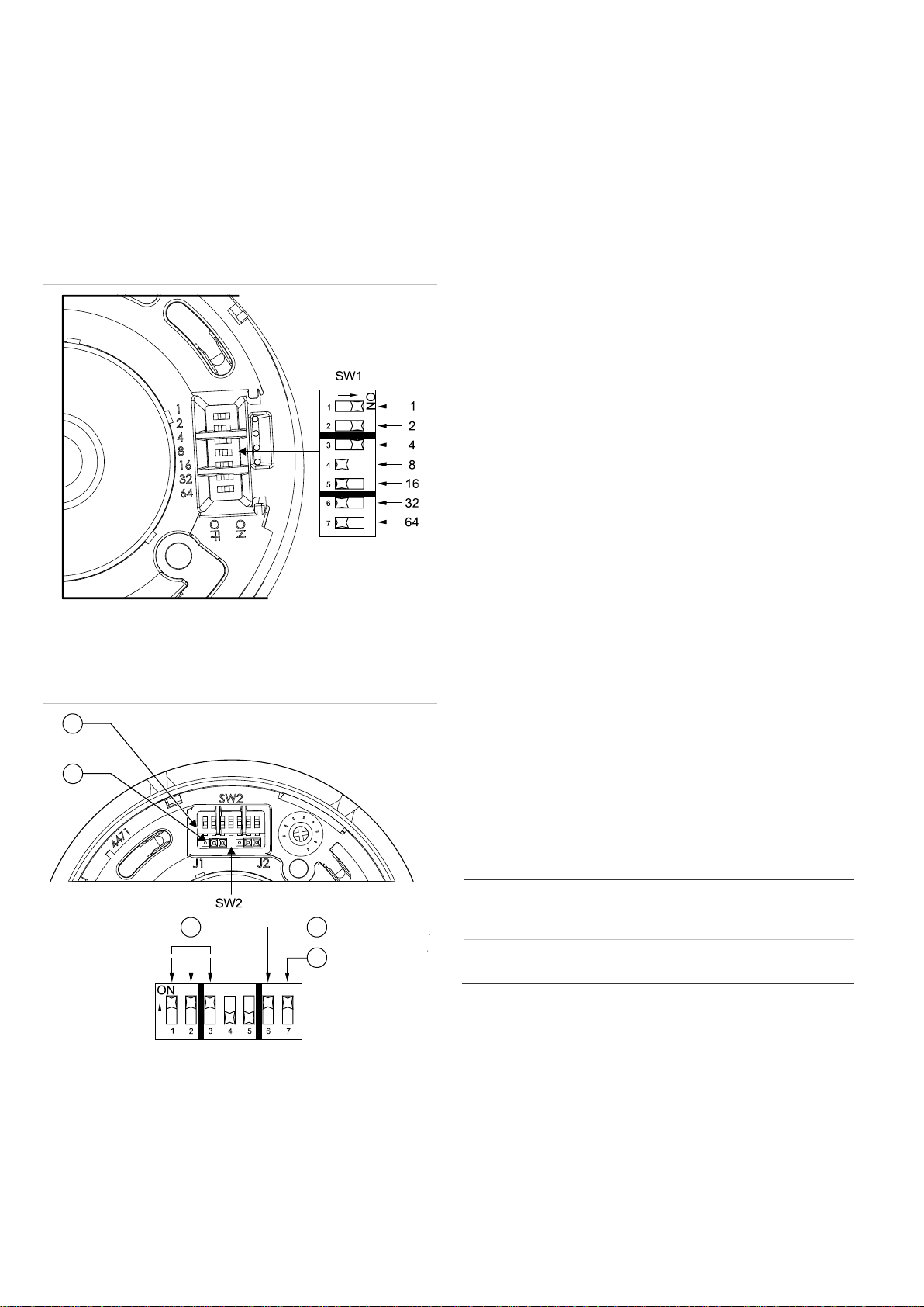
Setting the address
The sounder includes a seven-segment DIP switch (SW1) for
assigning device addresses. Each switch segment represents
the value shown in Figure 3. The address is the sum of all the
switch segments in the ON position. The switch is used to set
the device address in binary code. The switch may be set to
represent any address from 1 to 127.
For example, to select a device address of 007, set SW1-1,
SW1-2, and SW1-3 to the ON position and the remaining
switch segments to the OFF position.
Figure 3: Address switch setting
Mode and tone settings
The sounder includes a seven-segment DIP switch (SW2) to
select operating mode, device mode, and tone. See Figure 4.
Figure 4: Mode of operation switch settings
1. Power selection jumpers
2. SW2 configuration switch
3. Tone
4. Device mode
5. Operating mode
Setting the operating mode
The sounder has 2 modes of operation, which are selected
using SW2-7. It can operate as a stand-alone sounder with its
own unique loop address, or as a dedicated sounder with an
address matched to the detector address.
To configure operation as a stand-alone sounder:
1. Set SW2-7 to ON.
2. Navigate to the following menu to tag the sounders as
SAB:
ZP3 Panel Menu/Setup/Sounders/SAB/Add SAB
The Planner can also be used.
3. To map an alert-to-evac function, make the first input type
a fast flash input.
The sounder will sound the alert tone in response to a fast
flash input or an evac tone when the input configured as
steady is triggered, overriding the alert tone.
To configure operation as a dedicated sounder:
1. Set SW2-7 to OFF.
2. Navigate to the following menu to configure the sounder
for use with a detector:
ZP3 Panel Menu/Setup/Sounders/Add SAB
The Planner can also be used.
3. Only one sounder tone option is available: Secondary
sound types.
ZP3 firmware 71910 v 3.11 and earlier:
If a sounder is set to the same address as a detector, then
the sounder sounds automatically when that detector
operates. All other required operations need programming
at the panel.
Note: The secondary tone is selected whether triggered by a
fast flash or steady flash.
Setting the device mode
SW2-6 selects whether the loop sounder operates in ZP755
mode or in ZP754 emulation mode as described in Table 2.
Table 2: SW2-6 mode selection switch
Mode SW2-6 Output signal Requirement
ZP755 OFF User-selectable two-
tone operation and
full monitoring
ZP3 software v1.18 or
later
ZP754
emulation ON Two fixed tones
ZP5 panels or ZP3 panels
with legacy software
Setting the tone
Two different tones can be programmed to operate from the
panel. In ZP755B-2 mode these tones are selected using
SW2-1, SW2-2, and SW2-3. Refer to Table 3.
Note: In the ZP panel I/O mapping menu, outputs are
programmed as "steady" or "flashing." The link to the table
below is as follows:
• Tone A = Panel setting "fast flash/slow flash.”
• Tone B = Panel setting "steady.”
3
1
2
4
5
www.acornfiresecurity.com
www.acornfiresecurity.com
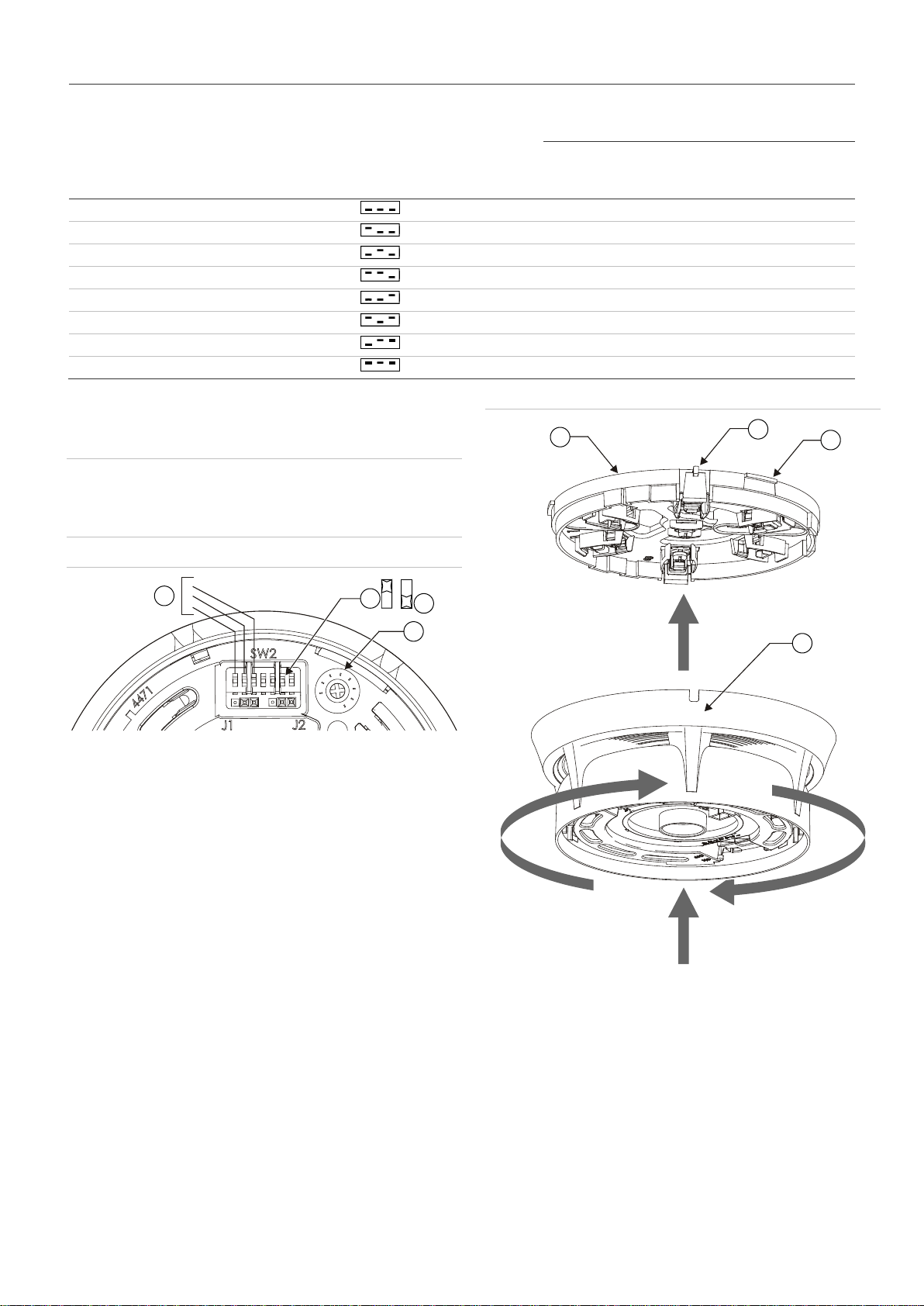
Table 3: Tone settings
SW2-6 device mode
switch setting Device mode SW2 switch setting
-1 -2 -3 Mapping input type
Fast flash Steady
Tone type
Tone A primary/alert Tone B secondary/evac.
OFF ZP755 0 Intermittent Continuous
OFF ZP755 1 Continuous Intermittent
OFF ZP755 2 Continuous Two-tone
OFF ZP755 3 Two-tone Continuous
OFF ZP755 4 Two-tone Intermittent
OFF ZP755 5 Intermittent Two-tone
OFF ZP755 6 Not used
ON ZP754 7 Intermittent Continuous
Setting the volume
The sounder has a volume control potentiometer to adjust the
volume. Refer to Figure 5.
WARNING: To conform to EN 54 Part 3 sound output levels,
the volume control must be set to the full clockwise position. If
the volume is adjusted for any reason, it must be returned to
the full clockwise position.
Figure 5: Volume control
1. Tone select
2. SW2-6 on
3. SW2-6 off
4. Volume control
Mounting the sounder onto the base
Refer to Figure 6. Align the addressable sounder to the plug-in
base. Push up (A), and then turn the sounder until it clicks into
place (B). Push the sounder up once more to engage (C).
Reverse the above procedure to remove the sounder from the
base.
Figure 6: Mounting
1. Addressable sounder
2. Release aid (3X)
3. Release/lock catch
4. Plug-in base
Sounders per loop
The sounder can be powered directly from the loop of a ZP5 or
ZP3 panel. Use Figure 7 in conjunction with Table 4, to
determine the quantity of detectors and sounders that can be
connected to a two-core shielded loop.
1
2
3
123
4
4
3
2
1
A
B
C
www.acornfiresecurity.com
www.acornfiresecurity.com
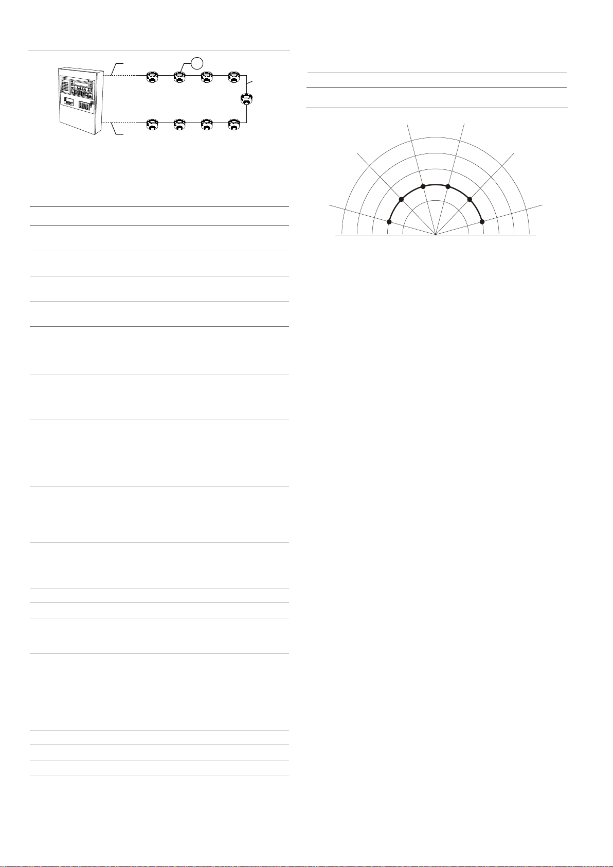
Figure 7: Detector/sounders per loop
A. Cable length panel to first sounder
B. Cable length first to last sounder
C. Cable length last sounder to panel
1. Detectors and Sounders
Table 4: Maximum detectors and sounders per loop
A B C Quantity allowed [1]
10 m 980 m 10 m 50 detectors and 50 sounders
63 detectors and 42 sounders
100 m 800 m 100 m 45 detectors and 45 sounders
63 detectors and 40 sounders
200 m 600 m 200 m 40 detectors and 40 sounders
63 detectors and 37 sounders
300 m 400 m 300 m 37 detectors and 37 sounders
63 detectors and 35 sounders
[1] Using a two-core shielded loop of 1000 meters cable size 1.5 mm²
Specifications
Operating voltage
External supply
Loop supply, ZP protocol
18 to 30 VDC
19.5 to 20.5 V pulsed, max. 4 V line
loss
Current (line powered)
Quiescent (RMS)
Alarm (RMS)
Alarm (excluding device
address)
Alarm (at device address)
820 µA
4.5 mA
7.5 mA max.
23 mA max.
Current (externally powered)
Quiescent (RMS)
Alarm (RMS)
Maximum number
470 µA
500 µA
60 per 1 km loop (subject to cable
size and sounder spacing)
Sound output
Tone 1
Tone 2
Tone 3
70 dBA.
Continuous 980 Hz
Intermittent 980 Hz (0.5 sec. on/off)
Two-tone warble 980 Hz/670 Hz
Sound distribution Wide
CNPP anechoic sound levels See Figure 8
Monitoring
ZP loop
Sound output level
Open and short circuit fault
Self test facility
Construction
Material
Weight
Dimensions (Ø × D)
ZP710/ZP730
ZP720
ZP732/ZX732
Moulded thermoplastic
150 g
127 × 69 mm
127 × 90 mm
127 × 90 mm
127 × 97 mm
Compatibility Ziton analogue addressable systems
Addressing method 7-segment DIP switch
Mounting Surface, with plug-in base
Wiring Two-core loop
Operating environment
Temperature
Relative humidity
−10 to +60°C
10 to 95% noncondensing
Storage temperature −20 to +70°C
Figure 8: CNPP anechoic sound levels
A
C
B
1
165
O
105
O
75
O
45
O
15
O
135
O
dBA 65 70 75 80 856570758085
www.acornfiresecurity.com
www.acornfiresecurity.com
Other Ziton Accessories manuals


