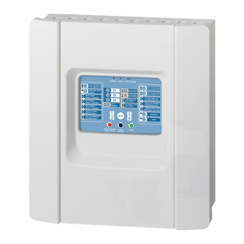
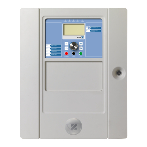
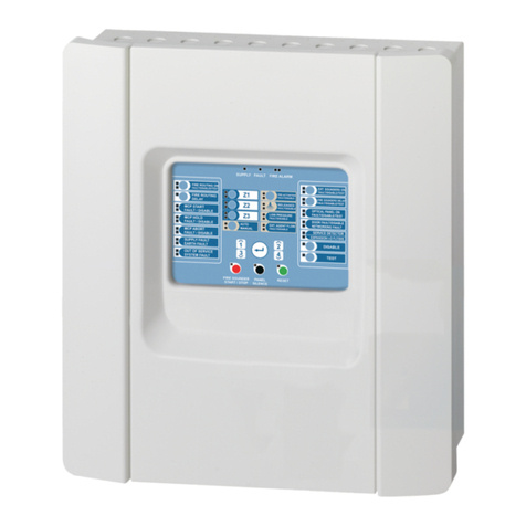
Ziton ZP3 Owner's manual

ZITON
ZP3
Fire Control Panel
Installation
Operation
Maintenance


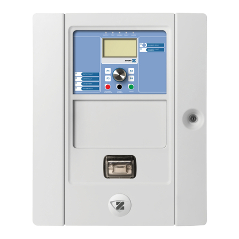
ZP3 Fire Control Panel
Installation
Operation
System Maintenance
Document no. 1160
Issue 06
Published 25 February 2005
ISSUE HISTORY
Issue Date Version Details
5 21/01/2005
6 25/02/2005

ZP3 Fire Control Panel
Installation
Operation
System Maintenance
Document no. 1160
Issue 06
Published 25 February 2005
This document is copyright by Ziton, and all rights are reserved. It may not be photocopied,
translated, or reduced to a machine readable form, in whole or in part, without the prior written consent
of Ziton Ltd. It may not be distributed with changes or omissions, which have not been authorized by
Ziton Ltd.
Although Ziton has reviewed and checked this documentation, and believes it to be accurate, Ziton
gives no warranty or representation, either expressed or implied, with respect to accuracy,
completeness, or errors.
For further information, please contact Customer Support at one of the following Ziton Centres.
Ziton Ltd
8 Newmarket Court
Chippenham Drive, Kingston
Milton Keynes MK10 0AQ
United Kingdom
Ziton (Pty) Ltd
555 Voortrekker Road
Maitland
7405
South Africa
Telephone: +44 (0)1908 281981
Fax: +44 (0)1908 282554
Email: zitonuk@ziton.spx.com
Telephone: +27 (0)21 506 6000
Fax: +27 (0)21 506 6050
Email: zitonsa@ziton.spx.com

ZP3 Fire Control Panel
Installation Manual
Table of Contents
System Overview
1.1 The ZP3 System ..............................................................................................................1-1
1.1.1 Introduction ...................................................................................................................... 1-1
1.1.2 Basic System Features .................................................................................................... 1-2
1.1.3 Standards......................................................................................................................... 1-5
1.1.4 Sensors and Devices .......................................................................................................1-6
1.1.5 Accessories and Peripherals ........................................................................................... 1-7
1.1.6 System Operation ............................................................................................................ 1-8
1.2 System Architecture .........................................................................................................1-9
1.2.1 Overview .......................................................................................................................... 1-9
1.2.2 The Z-Loop..................................................................................................................... 1-10
1.2.3 The ICB (Internal) Control Bus....................................................................................... 1-11
1.2.4 The SCB (External) Control Bus .................................................................................... 1-12
1.2.5 Communication Ports..................................................................................................... 1-13
1.2.6 Control Outputs .............................................................................................................. 1-14
1.2.7 Control Inputs................................................................................................................. 1-15
1.2.8 Peer-to-Peer Networking ............................................................................................... 1-16
ZP3 Panel
2.1 Introduction ...................................................................................................................... 2-1
2.2 Specification..................................................................................................................... 2-2
2.2 Specification..................................................................................................................... 2-3
2.2 Specification..................................................................................................................... 2-4
2.3 Display and Controls ........................................................................................................2-6
2.4 Panel Construction........................................................................................................... 2-7
2.4.1 Modular Format................................................................................................................ 2-7
2.4.2 Internal Features .............................................................................................................. 2-8
2.4.3 Main Chassis Assembly................................................................................................... 2-9
2.4.4 Door Assembly............................................................................................................... 2-11
2.4.5 Internal Wiring ................................................................................................................ 2-12
2.4.6 Earth Bonding ................................................................................................................ 2-13
2.5 Built-in Communication Port .......................................................................................... 2-14
2.5.1 RS232 Built-in Serial Port .............................................................................................. 2-14

2.6 Optional Modules ........................................................................................................... 2-16
2.6.1 Communication Boards.................................................................................................. 2-16
2.6.2 ZP3AB-RS232 Serial Communications Board (Z-Port 1a) ............................................ 2-17
2.6.4 ZP3AB-NET1 Network Board (Z-Port 2) ........................................................................ 2-23
2.6.5 Auxiliary Chassis............................................................................................................ 2-26
2.6.6 Mounting Auxiliary Boards ............................................................................................. 2-27
2.6.7 Auxiliary Boards and Modules ....................................................................................... 2-28
2.6.8 Printer............................................................................................................................. 2-28
2.7 Quick Start ..................................................................................................................... 2-29
2.8 Packing/Unpacking ........................................................................................................ 2-30
Power Supply
3.1 General Description .........................................................................................................3-1
3.2 Electrical Ratings ............................................................................................................. 3-2
3.3 Installation ........................................................................................................................ 3-5
3.4 Fuses and Indicators........................................................................................................3-7
3.5 Mains Connection ............................................................................................................3-9
3.6 Battery Connection ........................................................................................................ 3-11
3.7 Internal Power for Accessory Boards ............................................................................ 3-13
3.8 External Power for Accessory Boards ........................................................................... 3-14
3.9 Monitoring External Power............................................................................................. 3-15
3.10 Power Supply and Battery Calculations......................................................................... 3-15
Installation
4.1 Installation Overview ........................................................................................................ 4-1
4.2 Preparatory Work............................................................................................................. 4-2
4.3 Cable Entry ...................................................................................................................... 4-3
4.4 Wiring ............................................................................................................................... 4-4
4.5 Surface Mounting ............................................................................................................. 4-4
4.6 Flush Mounting................................................................................................................. 4-6
4.7 Top Wiring Tray................................................................................................................ 4-6
4.8 Good Practice .................................................................................................................. 4-8
Field Wiring
5.1 Terminal Layout ............................................................................................................... 5-1
5.2 Power Supply................................................................................................................... 5-2
5.2.1 Mains Supply.................................................................................................................... 5-2
5.2.2 Auxiliary 24 volt DC Supply.............................................................................................. 5-3
5.3 The Z-Loop....................................................................................................................... 5-4
5.3.1 Z-Loop Wiring................................................................................................................... 5-4
5.3.2 Loop Isolators................................................................................................................... 5-5
5.3.3 Z-Loop Parameters .......................................................................................................... 5-6
5.4 Common Outputs ............................................................................................................. 5-7
5.4.1 Common Sounder Outputs .............................................................................................. 5-7
5.4.2 Common Fire / Fault Outputs........................................................................................... 5-8
5.4.3 Remote Manned Centre Outputs ..................................................................................... 5-9
5.5 Auxiliary Boards ............................................................................................................. 5-10
5.5.1 ZP3AB-RL8 Relay Board ............................................................................................... 5-10
5.5.2 ZP3AB-MA8 Monitored Output Board............................................................................ 5-11
5.5.3 ZP3AB-OP24 Transistor Output Board.......................................................................... 5-12
5.5.4 ZP3AB-MIP8 Input Board .............................................................................................. 5-13
Software Programming
6.1 Introduction ...................................................................................................................... 6-1
6.2 Setup Menu...................................................................................................................... 6-2
6.2.1 Menu Operation ............................................................................................................... 6-2
6.2.2 Menu Structure................................................................................................................. 6-5
6.2.3 Menu Functions................................................................................................................ 6-7
System Configuration
7.1 System Configuration....................................................................................................... 7-1
7.1.1 System Specification........................................................................................................ 7-1
7.2 Sensor Selection and Configuration ................................................................................ 7-5
7.2.1 Engineering judgment ......................................................................................................7-5
7.3 Cause and effect functions .............................................................................................. 7-6
7.3.1 Input-Output Mapping ......................................................................................................7-6
7.3.2 Input-Output Mapping ......................................................................................................7-7
7.3.3 Point Address Structure ...................................................................................................7-7
7.4 System Address List ........................................................................................................ 7-9
7.4.1 SystemBus Addresses ..................................................................................................... 7-9
7.4.2 UserBus Addresses ....................................................................................................... 7-12
System Commissioning
8.1 Introduction ...................................................................................................................... 8-1
8.2 Verification ....................................................................................................................... 8-1
8.3 System Tests ................................................................................................................... 8-3
Peer-to-peer 3 Protocol
9.1. Introduction ...................................................................................................................... 9-1
9.2. New data structure ........................................................................................................... 9-1
9.3. Compatibility with Maestro and Planner .......................................................................... 9-1
9.4. Peer-to-Peer 3 (P2P3) Protocol ....................................................................................... 9-1
9.4.1 Overview .......................................................................................................................... 9-1
9.4.2 Compatibility with older versions of Panel software......................................................... 9-2

9.4.3 PP3 new features............................................................................................................. 9-2
9.5. Panel Filters Set, Store and Send Capability................................................................... 9-3
9.6. New Network Filters ......................................................................................................... 9-4
9.6.1 Filter description............................................................................................................... 9-4
9.6.2 Use of network communications filters ............................................................................ 9-5
9.7. Language Loading ...........................................................................................................9-6
9.8. Debug Comms Message ................................................................................................. 9-7
Appendices
O Operator Instructions ..........................................................................................Appendix O
M Maintenance Instructions ................................................................................... Appendix M
E EN54 Setup Requirements ................................................................................. Appendix E
W ZP Wiring Guide Document GA322................................................................... Appendix W

Procedures in this manual should only be carried out by Trained Service Personnel.
The ZP3 panel is powered from a 230 volt AC primary supply and from a 24 volt DC battery backup
supply.
Primary Supply
Connection to the 230 volt AC primary supply (+10%: -15%), must comply with National wiring
regulations. The wiring shall be permanently connected to the building wiring through a 10 amp 3 core
cable, and a double pole 10 amp isolation switch.
Care must be taken to wire the primary supply to the correct terminals:
Live = Brown
Neutral = Blue
Earth = Green/Yellow
The earth wire must NOT be omitted.
The incoming mains fuse only breaks the live connection. Be aware that even when the fuse is
withdrawn, there remains dangerous potential on the incoming terminals. It should also be noted that
dangerous potentials can exist at other locations on the PC board even with mains and battery
disconnected.
Back-up Battery Supply
The back-up batteries, although at only 24 volts DC, carry enough charge to be dangerous.
Care must be taken when connecting batteries, or when working in the vicinity of the battery terminals,
to not accidentally cause a short circuit. In particular metallic tools or metallic watch straps, is causing
an accidental short circuit, can cause burns to the user.
SAFETY


ZP3
Fire Control Panel
Installation Manual
Section 1
System Overview
UD1160.1
Issue 6
25/02/2005


ZP3 Fire Control Panel
System Overview
ZP3 Fire Control Panel Manual
UD1160.1 Iss 6 (25/02/2005) Page 1 - 1 I1
1.1 The ZP3 System
1.1.1 Introduction
The ZP3 is a sophisticated intelligent fire detection system, designed for the protection of
both small and large buildings, as well as very large multi-building sites. It uses a modular
design, which allows scalability from single panel systems, through to large multi-panel
networked systems. A range of hardware and software is available which allows purpose-
made applications for all commercial and industrial sites.
ZP3 is an analogue addressable system based upon the Ziton ZP operating system.
It utilizes advanced fire and smoke sensing techniques, with intelligent software, which
accurately recognizes real fires, and provides early warning. Precision algorithms identify
and, in most cases, eliminate false alarms. The location of a fire is accurately identified.
The ZP3 system supports both wired and wireless (radio) sensors, callpoints, and other
devices, providing a high degree of flexibility. A system comprises one or more ZP3 control
panels, connected to fire and smoke sensors, and other equipment to provide all the
necessary functions. Modular hardware includes remote indicator panels, mimic panels,
local and remote inputs and outputs for interfacing to third-party equipment, and interfaces to
computer-based monitoring and building management systems. Highly configurable
software allows virtually any system requirement to be simply programmed as required. The
ZP3 system is suitable for both new buildings and existing installations.
The complete system is actively monitored on a continuous basis, and provides complete
reliability at all times. Self-maintenance and diagnostics are built-in.
ZP3 fire alarm panels are available in 1, 2 and 4 loop versions, supporting up to 508 sensors
per panel. Built-in peer-to-peer networking capability allows up to 100 panels and over
50,800 sensors to be connected together, providing scalability from small to very large
systems.
The complete ZP3 system is designed to comply with those parts of European Standard
EN54, which have been published. When setup in accordance with the appendix E to this
manual ZP3 panels comply with EN54 (parts 2 and 4), and sensors comply with EN54 (parts
5, 7, and 8). Other parts of the system comply with the appropriate parts of relevant National
Standards, such as BS5839.

ZP3 Fire Control Panel
System Overview
ZP3 Fire Control Panel Manual
Page 1 - 2 UD1160.1 Iss 6 (25/02/2005)
I1
1.1.2 Basic System Features
The ZP3 system incorporates a wide range of features and capabilities. These are
described in detail later in this manual. The following is a list of the basic features available.
• The ZP3 incorporates the proven ZP system of automatic contamination adjustment
for each sensor. This recalibrates each sensor as it becomes contaminated, and
provides a constant sensitivity even when sensors are dirty.
• Each sensor is individually adjustable for sensitivity, including different sensitivities for
day and night operation.
• Selectable alarm verification allows the time integration of each sensor to be set.
Analogue sensors provide pre-alarm, alarm, service, and diagnostic alarms.
• Every sensor is continuously checked by the panel for contamination, with automatic
alarm.
• The system supports both fire and non-fire monitoring functions.
• The ZP-loop provides for addressable loop-powered sounders, reducing wiring.
• Each panel supports up to 50 zones, optionally 128. Built-in zone LED's display up to
50 zones, and extender panels provide LED display up to 128 zones.
• Each panel has the capability for 896 programmable inputs and outputs, which can be
located with the panel, or remotely via serial connection.
• Flash memory retains all programming and data, even if the panel is powered-down.
Operation
The panel incorporates a simple and effective operator interface with 160-character LCD
display. Together with zone LED's and function LED's, these indications give a clear and
unambiguous indication of all alarms and reports. All control functions are menu driven, and
three access levels are protected by codes. A "help" button provides quick access to
operating instructions.

ZP3 Fire Control Panel
System Overview
ZP3 Fire Control Panel Manual
UD1160.1 Iss 6 (25/02/2005) Page 1 - 3 I1
Sensors and devices
A full range of single and combination analogue addressable sensors, including wired and
radio sensors, is supported. Manual call-points meet UK preferences, and respond in less
than 3 seconds. A range of input and output interface units allows the connection of third-
party equipment to the addressable ZP-loop.
The following features are contained in panel software SW71910 version 2.12 and 3.07.
1. Less than 3 second sounder response from a mapped call point: The panel now has a
less than three second response time in response to a call point operation. This is in
compliance with BS5839-1:2002 specification.
For guaranteed under three second sounder response from a mapped call point input
the user must adhere to the following when using panel software SW71910 version 2.12
and 3.07.
The panel must be fitted with line driver software SW72001 version three. The call
point must be a version three type (ZP785-3).
The sounder and the call point must be on the same panel. The detection zone and
alarm zone thus needs to be serviced by the same panel.
For the output mapping the sounder output device must be defined as a sounder
type with the call point being the input trigger.
For a ZP755 line sounder used as a behind detector sounder the output address
must be tagged as a SAB (sounder alarm base).
2. Type 54 emulated devices improved functionality: A type 54 emulated device can be
mapped to disable any other line device. This will be reported on the panel as an event
and be updated in the Event archive.
Maintenance features
A range of maintenance features simplifies and improves system maintenance. These
include status reports, contamination and near-service reports, operational statistics, and a
"zone walk-test" and "sounder-test". The system has the ability to manually, or automatically
by time, disable zones or individual points for maintenance purposes.
Remote Diagnostics
Remote diagnostics is available as an optional, enabling some or all maintenance functions
to be carried out from a remote location.
Automatic Diagnostics
Automatic diagnostics continuously monitor the system for correct operation. Features
include automatic checking of wiring and points; corrupt data detection, disconnection of
faulty or corrupt zones, automatic testing of sensor operation, and verification of sensor/zone
location. Sensors are automatically subjected to a self-test at regular intervals, and vital
elements of the system, such as the software configuration data and running data are
verified every hour.

ZP3 Fire Control Panel
System Overview
ZP3 Fire Control Panel Manual
Page 1 - 4 UD1160.1 Iss 6 (25/02/2005)
I1
Accessories and peripherals
In addition to the ZP-loop devices, a range of accessories and peripheral devices is available
to provide all the elements of a complete system. These include remote display panels,
mimic panel drivers, addressable relay output boards, addressable monitored output boards,
addressable input boards, communication ports RS232 and RS485, remote I/O cabinets,
and other equipment.
Day/Night Capability
Day/Night control provides separate programmes for day and night modes. Different sensor
sensitivity, alarm selection, alarm evaluation delays, and fire brigade response can be
configured.
Configuration
An input/output programming facility allows any "cause-and-effect" requirement to be
configured. Each panel can have up to 896 outputs software linked to 2000 inputs in any
arrangement. All functions are 100% field programmable. This programming can be done
directly at the panel, or off-line at a computer. Flash memory retains all programming and
data, even if the panel is powered-down.
Communication and Integration
Multiple communication capability allows the panel to connect to printers, colour graphic
computers, building management systems, remote mimics and text displays, radio pagers,
and other systems. Simple integration into third-party systems is possible.
Peer-to-Peer Networking
The ZP3 peer-to-peer network enables up to 255 standalone systems (verified up to 100
systems) to be integrated to provide system-wide alarm reporting, co-ordinated evacuation,
cause-and-effect functionality, and control, for large systems and multi-building sites. The
maximum number of panels supported by each software version is listed in the table below.
Panel Software Max panels
Version 1 32
Version 2 64
Version 3 255

ZP3 Fire Control Panel
System Overview
ZP3 Fire Control Panel Manual
UD1160.1 Iss 6 (25/02/2005) Page 1 - 5 I1
1.1.3 Standards
The ZP3 panel when setup according to the appendix E to this manual complies with
European Standard EN54 parts 2 and 4, and meets all functional requirements of this
standard. In addition, the ZP3 panel also incorporates many features, which are specified by
EN54-2 as "options with requirements". These are described below.
Common sounders
EN54-2, paragraph 7.8
Two or four fully monitored common sounder circuits for operating sounders on any fire
alarm.
Co-incidence operation
EN54-2, paragraph 7.12
Optional operation whereby an alarm is only registered after response from two sensors in
the same zone. Initiation of a callpoint overrides the coincidence and raises an alarm.
Remote Manned Centre (Fire Alarm)
EN54-2, paragraph 8.9
Monitored fire alarm signal transmitted to a fire brigade, or other manned centre.
Remote Manned Centre (Fault Alarm)
EN54-2, paragraph 7.9
Monitored system fault signal transmitted to a fire brigade, or other manned centre.
Zone Walk Test
EN54-2, paragraph 10.0
One-man test of a zone of sensors/callpoints, or sounders, with full logging and reporting.
Control System Capability
EN54-2, paragraph 7.10
Optional outputs for controlling fire extinguishing systems, or other control functions, such as
shutdown of ventilation systems, closing of fire or smoke-control doors, etc.
Output Delays
EN54-2, paragraph 7.11
Manually selectable delays, available at level 2 access, to provide delays to certain outputs,
such as specific sounders or remote manned centre alarm. This operates in day/night mode.

ZP3 Fire Control Panel
System Overview
ZP3 Fire Control Panel Manual
Page 1 - 6 UD1160.1 Iss 6 (25/02/2005)
I1
Alarm Counter
EN54-2, paragraph 7.13
Menu based counter in maintenance mode, which provides a record of the number of alarms
from a specific date. Can only be reset by authorized personnel.
Delay on Sounder Silence
Not an EN54 requirement
The ability to programme a delay into the operation of the "Silence Sounders" key, to prevent
the accidental silencing of sounders before occupants have heard them.
Total Loss of Power
EN54-2, paragraph 8.4
Audible indication of the total loss of power of the standby power source when it can no
longer support mandatory functions. This alarm is audible for at least one hour.
1.1.4 Sensors and Devices
The following sensors and devices are supported by the ZP3 panel, when fitted with the
software specified in the specification. Later software may support additional or different
devices. If in doubt, check with Ziton.
ZP710 Ionization smoke sensor
ZP732 Combination smoke/thermal sensor
ZP730 Optical smoke sensor
ZP720-2 Thermal sensor (Grade 2)
ZP720-3 Thermal sensor (Class A1)
ZP785-2 Manual "breakglass" callpoint (indoor)
ZP785-3 Manual "breakglass" callpoint (indoor – 3 second response)
ZP787 Manual "breakglass" callpoint (outdoor)
ZP740 Interface unit, multifunction (fire/non-fire/security)
ZP745 Interface unit
ZP750 Loop relay
ZP755 Loop sounder
ZP756 Loop sounder with base
ZP753 Loop remote LED
ZP470 Loop radio communication module
ZP430 Wireless (radio) optical smoke sensor
ZP420 Wireless (radio) thermal smoke sensor

ZP3 Fire Control Panel
System Overview
ZP3 Fire Control Panel Manual
UD1160.1 Iss 6 (25/02/2005) Page 1 - 7 I1
ZP432 Wireless (radio) combination sensor
ZP485 Wireless (radio) callpoint
ZP440 Wireless (radio) interface I/O unit
ZP710ex Intrinsically-safe smoke sensor
ZP720ex Intrinsically-safe thermal sensor
ZP786ex Intrinsically-safe callpoint
ZP740ex Intrinsically-safe interface unit
ZP5-GCU Gas Control units
ZS200 High Sensitivity Aspirating Smoke Detectors
ZX832 Multisensor fire detector (optional)
1.1.5 Accessories and Peripherals
The following accessories and peripherals are supported by the ZP3 panel, when fitted with
the software specified in the specification. Later software may support additional or different
devices. If in doubt, check with Ziton.
ZP3-RDU Remote Display Unit (mini)
ZP3-RDU Remote Display Unit (full-function)
ZP3-RAC Remote I/O accessory cabinet
ZP3-RM Mimic panel
ZP3-RL8 Addressable relay board, 8-way
ZP3-MA8 Addressable sounder driver board (monitored), 8-way
ZP3-MIP8 Addressable input board, 8-way
ZP3-OP24 Addressable transistor output board, 24-way
ZP3-SCB-D Control bus driver board
ZP3-SCB-R Control bus receiver board
ZP3-NET1 Network driver board, single
ZP3-SB232 Serial communications board, RS232
ZP3-FX Fibre-optic interface unit
ZP3-FK1 Flush-mounting kit
ZP3-FC1 Flush collar

ZP3 Fire Control Panel
System Overview
ZP3 Fire Control Panel Manual
Page 1 - 8 UD1160.1 Iss 6 (25/02/2005)
I1
1.1.6 System Operation
The ZP3 is a complete intelligent fire detection system designed to protect life and property.
It will detect the presence of a fire or smoke, raise local and remote alarms, indicate
accurately the location of the fire, call the fire brigade, and activate building systems to
prevent the spread of smoke, gases, and fire. It can also activate automatic fire
extinguishing systems.
The ZP3 system consists of a central panel, which is connected to various devices, located
throughout the protected building. These devices include fire and smoke sensors, manual
callpoints, alarm sounders, local and remote indicating panels; graphics display computers,
led mimic panels, and other devices. Also connected are interface connections to other
building systems, and connections to a fire brigade, or other remote manned centre.
Sensing devices are grouped into zones, and programmed with text-labels to indicate their
location.
The control panel continually checks every fire and smoke sensor, callpoint, and other
devices, attached to the ZP-loop, every 2 seconds. The precision data collected is analysed
to indicate the amount of smoke, heat and combustion products in the proximity of devices.
This information is constantly updated because of the active scanning process by the ZP3
panel. This provides an accurate picture of the area being monitored by the sensors,
enabling intelligent decisions to be made on the presence or not of fire, smoke, or invisible
products-of-combustion.
After making a decision that a fire exists, the ZP3 system initiates an alarm at the control
panel, displays the exact location by means of illuminated LED's and LCD text-display, and
illuminates the led on the initiating sensors or callpoints. It also issues pre-programmed
commands to operate area sounders, call the fire brigade, activate building controls such as
air-conditioning shutdown, and other actions. In addition it commands remote devices to
display the location and status of alarms, and to carry out programmed control functions.
Very high power processing capability allows any configuration to be programmed. In large
multi-panel systems, panels communicate with each other, display alarms from other areas,
and carry out commands issued by other panels.
Other manuals for ZP3
2
Table of contents
Other Ziton Control Panel manuals

Ziton
Ziton ZP1-X3 User manual

Ziton
Ziton ZP3 Manual

Ziton
Ziton ZP3 User manual

Ziton
Ziton ZP2-F Series User manual

Ziton
Ziton ZP1-X3 User manual

Ziton
Ziton ZP1-X3E Series User manual

Ziton
Ziton ZP2 Series User manual

Ziton
Ziton zp1-f Series User manual

Ziton
Ziton zp1-f Series User manual

Ziton
Ziton ZP1-X3E Series User manual
Popular Control Panel manuals by other brands

Adaptec
Adaptec DuraStor 6200SR user guide

NAPCO
NAPCO Magnum Alert 1016LKDL installation instructions

auto maskin
auto maskin Marine Pro 200E Series Configuration manual

Distech Controls
Distech Controls LC-3 user guide

Haes
Haes ESG-2001 Installation, commissioning & operating manual

alre
alre b@home FTRCUd-210.021 operating instructions