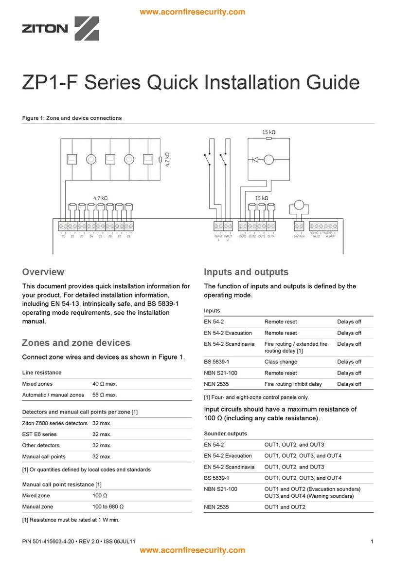
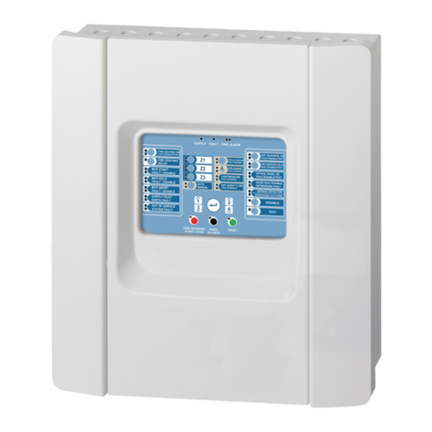
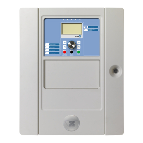
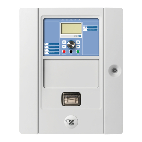
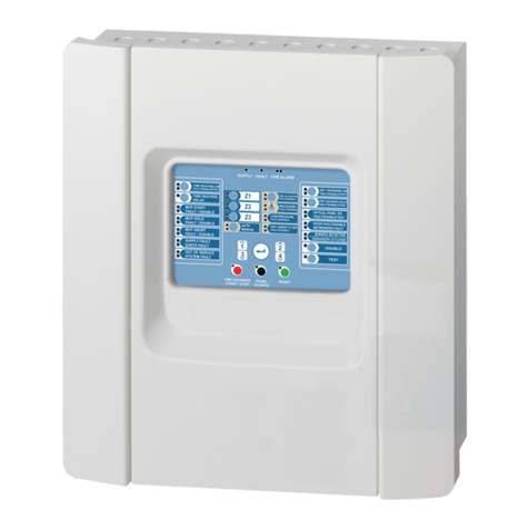
Ziton ZP3 User manual

ZP3 Fire Alarm Control
Panel Installatio
n Manual
P/N 10-3305-501-2003-01 • ISS 09MAR22

Copyright
©
2022 Carrier. All rights reserved.
Trademarks and
patents
The
ZP3 name and logo are trademarks of Carrier.
Other trade names used in this document may be trademarks or
registered trademarks of the manufacturers or vendors of the
respective products.
Manufacturer
Carrier Manufacturing Poland
Spółka Z o.o.,
Ul. Kolejowa 24, 39
-100 Ropczyce, Poland.
Authorized EU manufacturing representative:
Carrier Fire & Security B.V., Kelvinstraat 7, 6003 DH Weert,
Netherlands.
Revision
01
Firmware
compatibility
For control panels with firmware version
4.0 or later.
Compliance
European Union
directives
2014/30/EU (EMC
Directive). Hereby, Carrier declares that this
device is in compliance with the essential requirements and other
relevant provisions of Directive 2014/30/EU.
2012/19/EU (WEEE Directive): Products marked with this symbol
cannot be disposed of as unsorted municipal waste in the European
Union. For proper recycling, return this product to your local supplier
upon the purchase of equivalent new equipment, or dispos
e of it at
designated collection points. For more information see:
recyclethis.info
.
2006/66/EC (Battery Directive): This product contains a battery that
cannot be disposed of as unsorted municipal waste in
the European
Union. See the product documentation for specific battery
information. The battery is marked with this symbol, which may
include lettering to indicate cadmium (Cd), lead (Pb), or mercury
(Hg). For proper recycling, return the battery to your s
upplier or to a
designated collection point. For more information see:
recyclethis.info
.
Contact information
and product
documentation
For contact information or to download the latest product
documentation, visit
firesecurityproducts.com.

ZP3 Fire Alarm Control Panel Installation Manual i
Content
Important information iii
Chapter 1 Overview 1
Introduction 2
Panel overview 2
Optional modules 12
Quick start 24
Chapter 2 Installing the fire control panel 25
Unpacking or packing 26
Overview of installation 29
Preparatory work 31
Installation information 32
Chapter 3 Field wiring 39
Terminal layout 40
Power supply 41
Battery connection 45
Power supply and battery calculations 47
Z-Loop 50
Common outputs 53
Auxiliary boards 56
Chapter 4 LCD menus 61
Introduction 62
Setup menu 63
Chapter 5 System configuration 85
System specification 86
Cause and effect functions 90
System address list 94
EN 54 Setup requirements 99
Chapter 6 System commissioning 103
Introduction 104
Verification 104
System tests 107
Chapter 7 Peer-to-peer 3 protocol 111
Introduction 112
Peer-to-peer 3 (P2P3) protocol 112
Panel filters set, store and send capability 114
Network filters 114
Language loading 116

ii ZP3 Fire Alarm Control Panel Installation Manual
Chapter 8 ZP wiring guide 117
Introduction 118
System cabling 121
Z-Address lines 123
Serial communication lines 131
DC control lines 133
Chapter 9 Maintenance 135
Overview 136
Routine maintenance 137
Maintenance menu 140
Interpretation of analogue readings 148
Corrective maintenance 156
Chapter 10 Technical specifications 161
Appendix A Regulatory information 169

ZP3 Fire Alarm Control Panel Installation Manual iii
Important information
This is the installation manual for the ZP3 Fire Alarm Control Panel. Read these
instructions and all related documentation entirely before installing or operating
this product.
Firmware compatibility
Information in this publication covers ZP3 control panels with firmware version
4.0 or later.
This publication must not be used as a guide for installation, configuration, or
operation of control panels with an earlier firmware version.
Note: Control panels with firmware version 4.0 or later are compatible for use in
fire networks with control panels with firmware 3.12. However, control panels with
earlier versions of firmware cannot be upgraded to firmware version 4.0.
Product warnings and disclaimers
THESE PRODUCTS ARE INTENDED FOR SALE TO AND INSTALLATION BY
QUALIFIED PROFESSIONALS. CARRIER FIRE & SECURITY B.V. CANNOT
PROVIDE ANY ASSURANCE THAT ANY PERSON OR ENTITY BUYING ITS
PRODUCTS, INCLUDING ANY “AUTHORIZED DEALER” OR “AUTHORIZED
RESELLER”, IS PROPERLY TRAINED OR EXPERIENCED TO CORRECTLY
INSTALL FIRE AND SECURITY RELATED PRODUCTS.
For more information on warranty disclaimers and product safety information,
please check https://firesecurityproducts.com/policy/product-warning/ or scan the
QR code:

iv ZP3 Fire Alarm Control Panel Installation Manual
Advisory messages
Advisory messages alert you to conditions or practices that can cause unwanted
results. The advisory messages used in this document are shown and described
below.
WARNING: Warning messages advise you of hazards that could result in injury
or loss of life. They tell you which actions to take or to avoid in order to prevent
the injury or loss of life.
Caution: Caution messages advise you of possible equipment damage. They tell
you which actions to take or to avoid in order to prevent the damage.
Note: Note messages advise you of the possible loss of time or effort. They
describe how to avoid the loss. Notes are also used to point out important
information that you should read.
Product symbols
The following symbols are used on the product.
This symbol indicates that caution is necessary when operating or
maintaining the device or control close to where the symbol is placed.
This symbol indicates that the installation manual should be consulted
when operating or maintaining the device or control close to where the
symbol is placed.

ZP3 Fire Alarm Control Panel Installation Manual v
General warnings and precautions
Trained service personnel must carry out procedures in this manual.
The control panel is powered from a 230 VAC primary supply and from a 24 VDC
battery backup supply.
WARNING: Electrocution hazard. To avoid personal injury or death from
electrocution, remove all sources of power and allow stored energy to discharge
before installing or removing equipment.
Primary supply
WARNING: The power supply forms part of the main board assembly. This
assembly consists of a circuit board (incorporating the power supply), mounted
on a metal chassis, with the power supply covered by a metal enclosure. The
enclosure must not be opened, and non-authorized persons must never remove
the circuit board from the chassis. Very high voltage potentials exist on the circuit
board, and disassembling any part of the power supply could be dangerous to
field personnel.
Connection to the 230 VAC primary supply (+10%, −15%), must comply with
National wiring regulations. The wiring must be permanently connected to the
building wiring through a 10 A, 3-core cable, and a double pole 10 A isolation
switch.
The primary supply must be wired to the correct terminals as follows:
• Live = Brown
• Neutral = Blue
• Earth = Green/Yellow
Note: The earth wire MUST be connected for each installation.
Cautions
• The incoming mains fuse only breaks the live connection.
• Dangerous potential remains on the incoming terminals even when the fuse is
removed.
• Dangerous potentials can also exist at other locations on the PCB even with
mains and battery disconnected.

vi ZP3 Fire Alarm Control Panel Installation Manual
Backup battery supply
Caution: Risk of explosion if the battery is replaced by an incorrect type.
For recommended batteries, see Chapter 10 “Technical specifications”
on page 161.
WARNINGS
• The backup batteries, although at only 24 VDC, carry enough charge to be
dangerous.
• When connecting batteries, or when working in the vicinity of the battery
terminals, take care not to accidentally cause a short circuit. In particular
metallic tools or metallic watchstraps can also inflict severe burns to the user
as well as cause a short circuit.
Caution: The backup batteries contain substances that are potentially hazardous
to your health and to the environment.
List of abbreviations and acronyms
Table 1 below lists and defines the abbreviations and acronyms used in this
manual.
Table 1: Abbreviations and acronyms
Abbreviation
Definition
DC
Direct current
GND
Ground
LCD
Liquid crystal display
LED
Light emitting diode
mA
Milliampere
µ
F Microfarads
MICC
Mineral-insulated copper-clad
PC
Personal computer
RX
Receive
SAB
Sounder alarm base
SW
Switch
TX
Transmit
V
Volts

ZP3 Fire Alarm Control Panel Installation Manual 1
Chapter 1
Overview
Summary
This chapter provides a general overview of the control panel and optional
modules.
Content
Introduction 2
Panel overview 2
Product range 2
Display and controls 3
Panel construction 4
Built-in communication port 10
Optional modules 12
Communication boards 12
Remote display unit 18
Accessory plate 19
Printer 21
Quick start 24

Chapter 1: Overview
2 ZP3 Fire Alarm Control Panel Installation Manual
Introduction
The ZP3 Fire Alarm Control Panel is an addressable panel that complies with
EN 54 parts 2 and 4.
The control panel uses nonvolatile flash memory, and can be configured on site,
using the keypad or from a PC.
Figure 1: ZP3 Fire Alarm Control Panel
Panel overview
Product range
The ZP3 Fire Alarm Control Panel range includes the models shown in the table
below.
Table 2: ZP3 product range
Model
Description
71305N
ZP3-1L Fire Alarm Control Panel (Red)
71401N
ZP3-2L Fire Alarm Control Panel (English)
71403N
ZP3-2L Fire Alarm Control Panel (Spanish)
71405N
ZP3-2L Fire Alarm Control Panel (Red)
71501N
ZP3-4L Fire Alarm Control Panel (English)
71503N
ZP3-4L Fire Alarm Control Panel (Spanish)
71505N
ZP3-4L Fire Alarm Control Panel (Red)

Chapter 1: Overview
ZP3 Fire Alarm Control Panel Installation Manual 3
Display and controls
The fascia of the control panel has the necessary indicator lamps, text display
screen, controls, menu keyboard, and printer to provide the operator with the
status of the system at all times. It also has a reporting system for alarms, faults,
and other events. Figure 2 shows the main features of the front panel.
Figure 2: Main features of the panel
1. Zone fire indicators
2.
Help button
3.
Views points button
4. LCD text display
5. Scroll buttons
6.
Sounder control keys
7.
Alarm view buttons
8. Access control
9. Status indicators
10.
Keypad
11.
Printer
12. Day/night module
The display of information is designed to comply with the requirements of
EN 54-2. In addition to alarms and events being reported on the text screen, they
are also indicated on zone lamps where applicable. Operation of controls is
structured by access level, with four levels being provided. The printer is an
optional item.
LOCAL ZONES
1
9
17
25
33
41
49
2
10
18
26
34
42
50
3
11
19
27
35
43
4
12
20
28
36
44
5
13
21
29
37
45
6
14
22
30
38
46
7
15
23
31
39
47
8
16
24
32
40
48
ZP3 FIRE ALARM SYSTEM
HELP
ACCEPT
MUTE
BUZZER
RESET FIRE FAULT DISABLED OTHER SILENCE
ALARMS SOUND
ALARMS
MORE
VIEW
POINTS
DISABLED DELAYED PRE-ALM TEST ENABLE CONTROL
ON
OFF
FAULTACTIVEPOWER ON
SYSTEMNIGHT
ZONEDAY
POINTMORE TIME
SOUNDERS
REMOTE ALARM
CONTROL OUTPUTS
RESTORE
DISABLED
ALARMS
1
ABC 2
DEF 3
GHI F1
F2
4
JKL
7
STU 8
VWX
0
[ ]
9
YZ
5
MNO 6
PQR
ESC
1
2 3 4
6
7
8
5
12 9
11 10

Chapter 1: Overview
4 ZP3 Fire Alarm Control Panel Installation Manual
Panel construction
Modular format
The control panel is of modular design so that it can be configured for any
required application. The basic panel operates as a complete system without any
extras. See Table 2 on page 2 for a complete list of the available panels.
Figure 3: Modular construction of the panel
Figure 3 shows the basic fire panel. The elements shown provide all required
functions, and form the core of the panel. No optional I/O modules or printer are
shown in this illustration. Up to three communication boards may be fitted.

Chapter 1: Overview
ZP3 Fire Alarm Control Panel Installation Manual 5
Internal features
Figure 4 shows the internal features of the basic panel with additional detail. All
components are carried on two main modules; the internal chassis holds the
main board and processor board, and the door assembly holds the display board,
the zone board, the keyboard, and the Zport 1 connection.
Figure 4: Internal features
1. Door assembly
2.
Main chassis
3.
Batteries
4. Field wiring entry
5. Main terminals
6.
Mains 230 VAC connections
7.
Mains fuse
8. Mains filter
The panel is divided into three main modules, namely the chassis, the door
assembly, and the cabinet. The basic electrical installation can be carried out
using the cabinet only, which has the required conduit entry points at the top and
back. Optional hardware is available for different installation requirements.

Chapter 1: Overview
6 ZP3 Fire Alarm Control Panel Installation Manual
Main chassis assembly
Figure 5 shows all the main features of the panel main chassis assembly. This
unit comprises the line drivers, the I/O circuitry, the control circuits, the power
supply, and the plug-in central processing unit (CPU).
Figure 5: Main chassis assembly
1
. Earth monitoring enabled
2
. Battery for time/date
3
. Chassis
4
. Field terminals
5
. LED 6 RMC alarm activated
6
. LED 10 RMC fault activated
7
. LED 12 common fire
8
. LED 11 common fault
9
. LED 13 sounder 3+4 activated
10
. LED 36 sounder 1+2 activated
11
. LED 1 battery charging
12
. LED 5 RMC alarm overload
13
. LED 9 RMC fault overload
14
. Monitored sounders 4 fuse (F3)
15
. Monitored sounders 3 fuse (F2)
16
. Aux/supply out fuse (F6)
17
. RMC fault alarm fuse (F5)
18
. Battery/external 24V fuse (F1)
19
. Monitored sounders 1 fuse (F8)
20. Monitored sounders 2 fuse (F7)
21
. Main 24 VDC power fuse (F9)
22
. 5 VDC power 0.5 A fuse (F10)
23
. Charge rate selector
24
. Power supply unit
25
. CPU board
26
. USB type A port
27
. USB type B port
28
. LED 4 mains on
29
. LED 2 RDU +ve
30
. LED 7 RS-232 +ve
31
. LED 8 RS-232 −ve
32
. LED 14 +5V_S
33
. LED 15 +5V
34
. LED 37 24V
35
. LED 20 sounder fault
36
. LED 19 loop fault
37
. LED 18 earth fault
38
. LED 21 ADC failure
39
. To auxiliary boards
40. To display PCB

Chapter 1: Overview
ZP3 Fire Alarm Control Panel Installation Manual 7
The main chassis is removed from the panel by removing the four securing
screws.
WARNING: Once removed, the main chassis should not be dismantled, as very
high voltage exists below the circuit board, and can be present even when mains
is off, or the unit is removed from power. There are no field-serviceable parts in
the assembly.
Door assembly
Figure 6 shows all the main features of the Door Assembly. This unit comprises
the panel display and control electronics as well as the keyboard, a serial
connection for data loading, and the printer (if fitted).
Figure 6: Door assembly
1. Display board
2.
Zone board
3. Optional printer
4 Earth straps
5.
Commissioning board
To remove the complete door assembly:
1. Remove the two screws securing the hinges.
2. Remove the four nuts securing the earth straps, which connect from door to
box.
3. Carefully unplug cables connecting the door boards to the main chassis.
Note: Do not dismantle the door boards. There are no field-serviceable parts in
the assembly.
1
5
2
3
4

Chapter 1: Overview
8 ZP3 Fire Alarm Control Panel Installation Manual
Internal wiring
Figure 7: Internal wiring

Chapter 1: Overview
ZP3 Fire Alarm Control Panel Installation Manual 9
Earth bonding
Figure 8: Earth bonding
1. Earth straps
2.
Chassis earthing nuts
3.
Earth connection to detector loop screens
4.
Building earth
5.
Filter earth
6.
Panel enclosure earthing stud
7. Earth path to chassis
8. Earth in cable to PSU
9.
Earth path to power supply cover
10.
Accessory plate earthing screw to chassis
11.
Earth path to accessory plate
12.
Contact clips
13.
Commissioning board

Chapter 1: Overview
10 ZP3 Fire Alarm Control Panel Installation Manual
Built-in communication port
RS-232 built-in serial port
The built-in RS-232 port is used to connect the panel to an external computer for
the purpose of uploading or downloading the panel’s configuration program.
Configuration programming is normally done on a PC using Planner (the Planner
for Windows programme) and then loaded into the panel at the site via a portable
PC.
Note: The preferred baud rate settings when using Planner to configure the
control panel are shown in Table 3 below.
Table 3: Baud rate settings
Baud rate Data bits Parity Stop bits
Receive
38400 8 Even 1
Send
9600 8 Even 1
Alternatively you can set Z-Port 1 to ZCP3 to allow control directly from Planner.
The protocol is RS-232, with a three-wire connection as shown in Figure 9. This
port shares internal lines with Z-Port 1a, and consequently the D-plug connection
to the ZP3AB-RS232 board must be physically disconnected before using the
built-in port.
Figure 9: RS-232 built-in serial port
1
14 25
13
15
6 9
15
6 9
9-pin D
connector 9-pin D
connector
25-pin D
connector
Cable connections
(Ziton RS-232 Type A Cable)
ZP3 Panel
(9-pin) Computer
(9-pin) (25-pin)
2
3
5
3
2
5
2
3
7
RX
TX
GND
TX
RX
GND

Chapter 1: Overview
ZP3 Fire Alarm Control Panel Installation Manual 11
RS-232 is officially specified as having a maximum cable length of 10 metres.
The connecting cable must be screened, and must be made-up as per Figure 9.
Alternatively, a standard null modem cable can be used.
Setup
The RS-232 built-in serial port (Z-port 1) must be configured and must be set to
match the communications parameters of the PC and program being used.
Access the communications parameters menu using the following menu path:
Setup > System Configuration > Peripheral Comms > Comms Parameters
The following screen is displayed.
Figure 10: Communications Parameters screen
To change a setting, move the bracket to the selected item, and press Enter.
The parameters are dependent on the program used. For Planner, set the
parameters as follows.
Note: The Z-port 1 settings must match the Planner COM settings.
Table 4: Z-port 1 configuration settings
Parameter
Remarks
Z
-PORT Enter Z-port number 1
Protocol
Enter the required protocol as follows:
0 = disable the port
11 = for use with Ziton Planner
18 = ZCP2-3 protocol
Setup
Enter the following setup data:
Baud rate = 38400
Data bits = 8
Parity = None
Stop bits = 1

Chapter 1: Overview
12 ZP3 Fire Alarm Control Panel Installation Manual
Optional modules
Communication boards
The standard fire panel has one built-in communication port, Z-Port 1, used for
programming. Additional ports are available as options for other functions, such
as connecting into a Ziton ZP-NET network, connecting to graphics display
computers, as well as to remote display units and remote control units. These
ports are installed as shown in Figure 11 below. Modules are connected to plug-
in sockets, and secured to posts with three M4 screws.
Figure 11: Communication boards
Item
Description Standard / optional Remarks
1.
Z-Port 1 Standard Connects to notebook computer for programming
of the panel using the Planner configuration
program.
2.
Z-Port 1a Optional Serial communication board ZP3AB-RS232 for
connecting to third party systems, such as building
management systems, graphics systems, and
automatic pager systems.
1
2
3
4
Other manuals for ZP3
2
This manual suits for next models
2
Table of contents
Other Ziton Control Panel manuals

Ziton
Ziton ZP1-X3 User manual

Ziton
Ziton ZP2 Series User manual

Ziton
Ziton ZP3 Manual

Ziton
Ziton ZP3 Owner's manual

Ziton
Ziton ZP1-X3 User manual

Ziton
Ziton ZP2-F Series User manual

Ziton
Ziton zp1-f Series User manual

Ziton
Ziton ZP1-X3E Series User manual

Ziton
Ziton ZP1-X3E Series User manual

Ziton
Ziton zp1-f Series User manual