Ziton ZP7BMR-50 User manual

FEATURES
• Microprocessor
controlled
• Range 5 – 50 Metres
• Range 50 – 100 Metres
• Unique simple alignment
• Loop powered
• Selectable alarm
thresholds
• Low current
consumption
• Automatic contamination
compensation
ZITON
ZP7BMR-50/100
Loop Powered
Analogue Addressable
www.acornfiresecurity.com

Installation Guide Index
Section
1. System Description (page 2)
2. System Operation (page 2)
3. Detector Positioning (page 2 to 4)
4. Installation (page 4 & 5)
5. Prism Targeting (page 5)
6. Alignment (page 5 to 7)
7. System Testing (page 7)
8. Connection and configuration Settings (page 8)
9. Detector Back View (page 9)
10.Address settings (page 10)
11.Clearances (page 11)
12.Technical Data (page 11)
13.Service/Application Notes (page 12)
14.Parts List (page 12)
15.Remarks (page 12)
www.acornfiresecurity.com

1. System Description.
The ZP7BMR-50/100 Detector comprises a Transmitter and Receiver contained within one enclosure.
The Detector installs to the building fabric between 0.5 and 0.6 metres from the ceiling.
The Transmitter emits an invisible infrared light beam that is reflected via a prism(s) mounted directly opposite
and with a clear line of sight. The reflected infrared light is detected by the Receiver and analysed.
The Detector has maximum lateral detection of 7.5 metres either side of the beam.
2. System Operation.
Smoke in the beam path will reduce the received infrared light proportionally to the density of the smoke. The
Detector analyses this attenuation or obscuration of light and acts accordingly.
Alarm thresholds of 25%, 35%, and 50% can be selected to suit the environment, where 25% is the most
sensitive. If the received infrared signal reduces to below the selected threshold, and is present for
approximately 10 seconds, a Fire condition is activated.
If the infrared beam is obscured rapidly to a level of 90% or greater for approximately 10 seconds a Fault
condition is activated.
This condition can be entered in a number of ways, for example, an object being placed in the beam path,
transmitter failure, loss of the prism(s), or sudden misalignment of the Detector. The fault condition will reset
within 10 seconds of the condition being rectified.
The Detector monitors long term degradation of signal strength caused by component ageing or build up of dirt
on optical surfaces. This operates by comparing the received infrared signal against a standard every 15
minutes. When the detector is showing AGC fault, the detector will still operate correctly indicating Alarm and
Fault as normal.
3. Detector Positioning.
It is important that the ZP7BMR-50/100 Detector is positioned correctly to minimise the detection time.
Experiments have shown that smoke from a fire does not rise directly upwards, but fans out or mushrooms due
to air currents and heat layering effects. The time to signal a fire condition depends on the location of the
Detector within the premises, the volume of smoke produced, construction of the roof, and ventilation
arrangements.
The maximum distance either side of the beam axis is found to be typically 7.5 metres for satisfactory detection
under flat ceilings.
Smoke layering, where smoke does not reach the ceiling level due to layers of static hot air is overcome by
mounting the Detector at the recommended height below the ceiling of between 0.5 and 0.6 metres, bringing
the infrared beam below the heat layer and into the smoke layer.
However, in all installations the latest national fire standards must be consulted. If there is any doubt on the
correct mounting height, positioning may be determined by smoke tests.
Single Beam
15 m 15 m
0.5
↔
7.5 m
Multiple Beams
0.3
↔
0.6 m
0.5 ↔7.5 m
www.acornfiresecurity.com

3.1. Detector Positioning In Apex Of Sloping Ceiling.
A ceiling is defined as sloping if the distance from the top of the apex to the intersection of the ceiling and
adjacent wall is greater than 0.6 metres. See Fig. 1.
When a Detector is positioned in the apex of a ceiling (See Fig. 2), the lateral beam distance covered (Υ) can
be increased in relation to the angle of pitch (Φ).
For Example:
If the pitch angle is 20 degrees, the lateral coverage can be increased from 7.5 metres either side of the beam
(Υ) to:
Υ= 7.5 + (7.5 x 20/100) metres
Υ= 9 metres
Therefore, with a roof pitch of 20 degrees the lateral coverage can be increased from 7.5 metres either side of
the beam to 9 metres either side of the beam, but only for the beam positioned in the apex. All other
calculations remain the same.
Limit to when a Detector must be positioned in roof apex
0
5
10
15
20
25
30
35
0 5 10 15 20 25
Width of Room in metres
Angle of Pitch
in degrees Limit
Detector must be positioned in apex
Roof can be defined as flat
Χ
Slope if Χ≥0.6 Metres
Υ
Υ
Υ
(max)
=
7.5
+
(7.5 x
Φ
/100)
Fig. 1. Fig. 2. Φ
www.acornfiresecurity.com

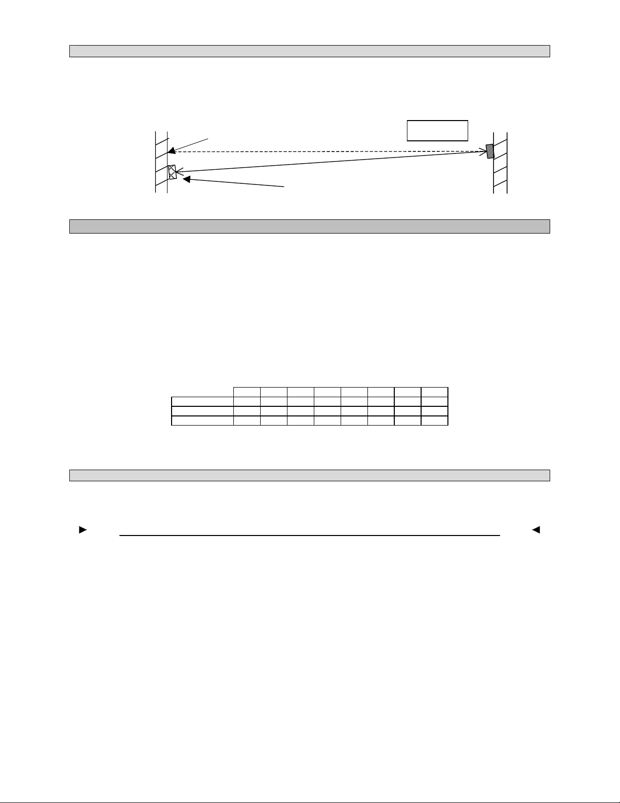
3.2. Detector Positioning In Atrium.
If the detector is to be placed in an atrium, or near glass/polished surfaces, the prism(s) should be offset from
the central line of sight (approximately 300mm), and angled back to the beam detector. This can be either on
the vertical or horizontal axis. This will reduce the amount of spurious returned signal from the glass/polished
surfaces. The reflected signal from the prism(s) will be returned to the detector in the normal way.
4. Installation.
Pre-installation at Ground Level.
Confirm that all parts have been supplied as listed in the parts list. See page 10.
Select the required alarm threshold using configuration switches 3 and 4 (See page 8, fig. 4. for switch
configuration settings). The factory default setting is 35% this should be adequate for most environments, if the
Detector is to be installed into an exceptionally dirty environment change the threshold to 50%.
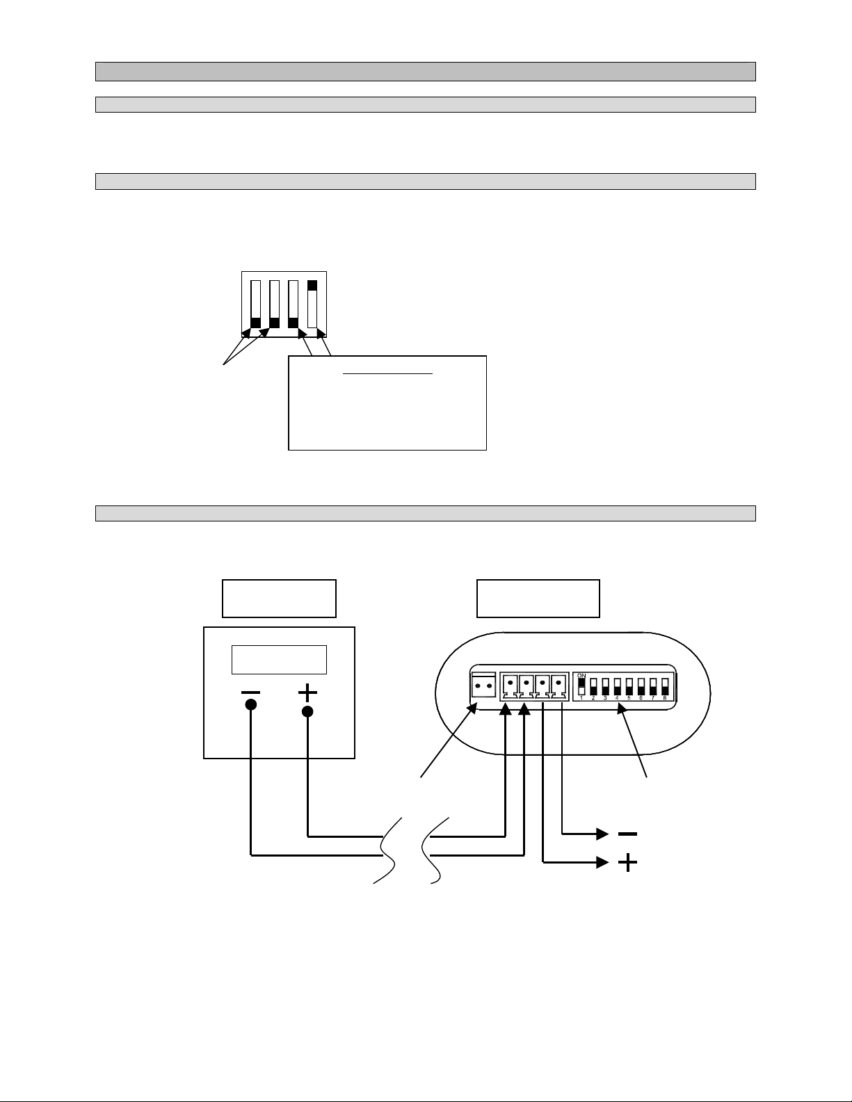
Select the required address using address switches 1 to 7 (See page 9, Table 1. for address switch settings)
where 1 is ‘ON’ and 0 is ‘OFF’. The factory default setting is address 1.
Shown below is an example of address 85 (1+4+16+64 = 85).
SW1 SW2 SW3 SW4 SW5 SW6 SW7 SW8
Switch Value 1 2 4 8 16 32 64 X
Switch Position ON OFF ON OFF ON OFF ON X
Logic 1 0 1 0 1 0 1 X
The Detector Head Assembly is now ready for installation. If configuration switches 3 and 4 require resetting
after installation, a power down reset is required (entering into Alignment Mode can also be used as a reset).
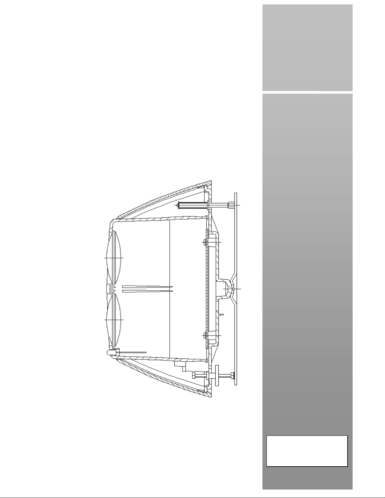
4.1. Detector Head Assembly Installation.
Remove the outer cover before installation; this is only to prevent the cover becoming dislodged during
handling.
Do not mount on plasterboard or cladded walls as these surfaces do, and will move.
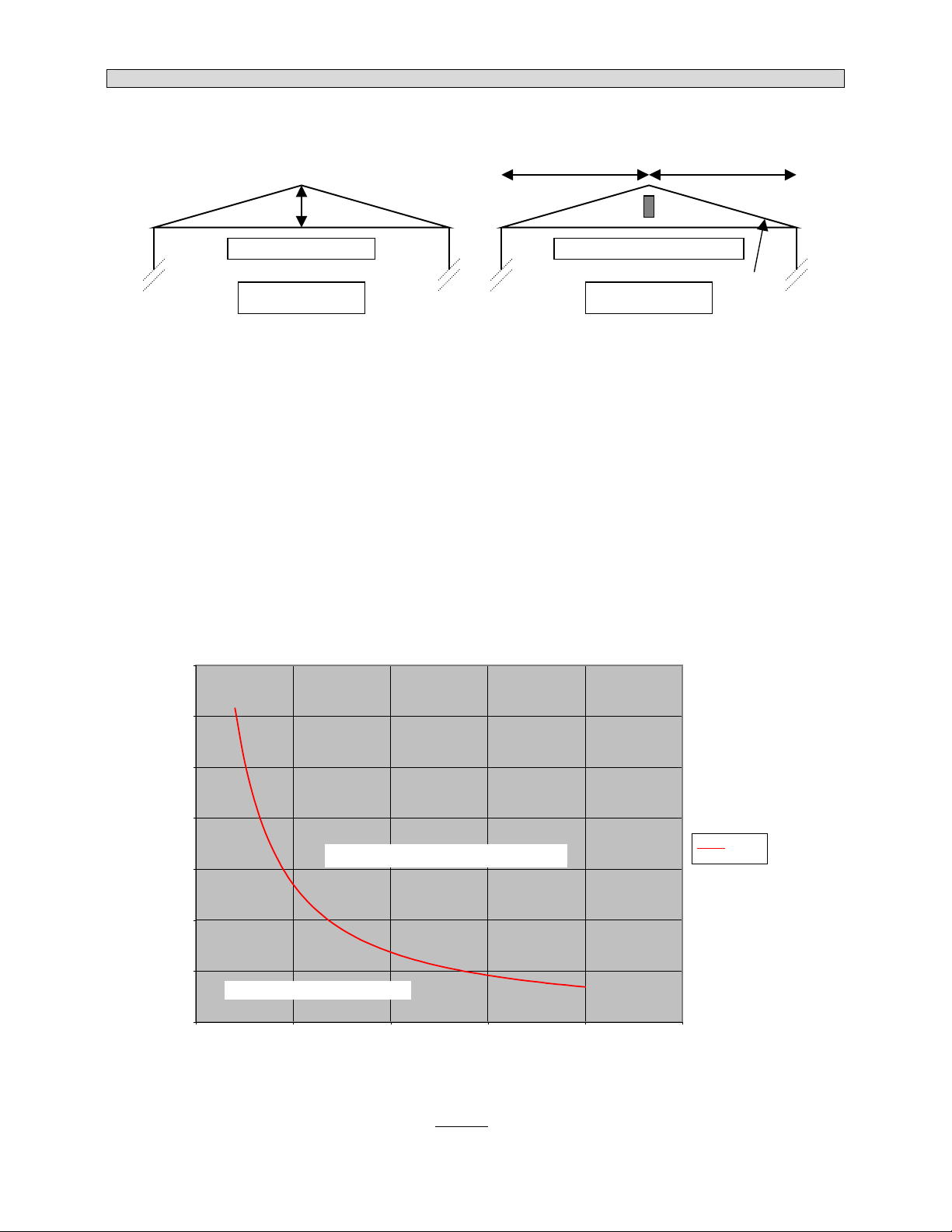
Determine the position of the Head Assembly, which must be mounted on a solid structure between 0.5 and
0.6 metres below the ceiling, and no closer than 0.5 metres to an adjacent wall or structure. Ensure that there is
a clear line of sight to the proposed position of the prism(s), which is to be mounted on a solid structure
between 5 and 100 metres directly opposite the Detector (range dependent on model).
Using the template provided mark and install all 4 fixing points to the structure. The rear mounting plate of the
Detector Head Assembly is provided with 4 keyhole slotted apertures to allow for easy installation onto the 4
fixing points. Install the detector on the four mounting points.
Replace the outer cover.
Terminate the field wiring. See section 8.
Offset Prism(s) position and beam path
Normal Prism(s) position and
central line of sight Detector
head
Plan View
www.acornfiresecurity.com

4.2. Prism(s) Installation.
Due to the principle of the detector i.e. reflective, the prism(s) must NOT be mounted on glass or a
polished reflective surface.
Mount the Prism(s) on a solid structure, 90º to the beam path, between 5 to 50 metres (ZP7BMR-50), and 50
to100 metres (ZP7BMR-100) directly opposite the Detector.
50R = 100R =
1 Prism 4 Prisms
Ensure that there is a clear line of sight to the Detector, taking care that no moving objects i.e. doors,
mechanical lifting equipment etc, will interfere with the beam path between the Detector and Prism(s).
Note: On ranges of ≥5 metres and ≤50 metres use a ZP7BMR-50.
On ranges of ≥50 meters and ≤100 meters use a ZP7BMR-100.
5. Prism Targeting Mode.
If the beam is less than 15 metres from the reflector ignore Prism Targeting mode and go to Alignment mode.
Apply power to the Detector. There is a pre-charge delay after power is applied to allow the internal circuits to
stabilise correctly.
Do not remove the detector from the wall during this action.
Using the mode switch (See fig. 4) select ‘Prism Targeting Mode’ (Switch will be in the up position). At this time
there will be a fault condition showing on the panel.
Find the prism(s) by adjusting the horizontal and vertical thumbwheels until the Amber LED is flashing. Both the
Red and Amber LED will be OFF when no signal is being received. The Red LED will start to flash when a weak
signal is received (the stronger the signal, the faster the flash rate). When the received signal is high enough
the Red LED will extinguish and the Amber LED will start to flash.
• At this point it is essential to test that the prism(s) and not another surface is
reflecting the beam.
This can easily be confirmed by covering the prism(s) with a non-reflecting surface and confirm that the AMBER
and RED indicators are OFF.
6. Alignment Mode.
Mechanical alignment is provided by two adjustment thumb wheels on two sides of the Detector, positioned just
behind the Detector Head cover. Adjustment is achievable in both axes.
6.1. Enabling Alignment Mode.
Do not remove the detector from the wall during this action.
Using the mode switch (See fig. 4) select ‘Alignment Mode’ (Move switch to the middle position). At this time
there will be a fault condition showing on the panel.
6.2. Adjustment in Alignment Mode.
The Detector will automatically adjust its infrared beam power and receiver sensitivity to give an optimum
receiver signal strength.
The alignment progress is indicated by the colour and state of the indicator lamp on the front of the Detector.
www.acornfiresecurity.com

A
mbe
r
Red
Red
Neither
A
mber
• FLASHING RED
The Detector is receiving too much signal and is attempting to reduce the infrared power output to compensate.
Wait at this point until the indicator lamp is OFF, this may take up to 20 seconds depending on the distance
between Detector and Prism(s), the shorter the distance the longer the time.
• FLASHING AMBER
The Detector is receiving a weak signal and is attempting to increase the infrared power output.
• OFF
The Detector has optimised the infrared power and receiver gain for the current orientation of the Detector
and Prism(s). This does not mean that the Detector to Prism(s) alignment is at its optimum, i.e. if the
power is too high, a misaligned Detector may be receiving a fringe reflection from another object.
• FLICKERING RED/AMBER
This state can occur sometimes. It means that the infrared power is stepping through the optimum setting
for the current orientation of the Detector and Prism(s).
6.3. Alignment Process Flow Diagram.
After selecting alignment mode
wait until both LED’s stop
flashing
Slowly turn the
thumbwheel in the
same direction
Reverse the
direction of the
thumbwheel
Exit Alignment
Mode and enter the
Operating Mode
LED
flashing?
Slowly adjust a thumbwheel in
one direction and observe the
LED’s
LED
flashing?
For optimum alignment,
deflection of the beam in all four
planes should cause the Amber
LED to flash first
Stop turning the
thumbwheel and
wait for the Red
LED to stop
flashing.
Stop turning the
thumbwheel.
Both
thumbwheels
adjusted?
Repeat the
process for the
other thumbwheel
No
Yes
www.acornfiresecurity.com

6.4. Exiting Alignment Mode.
Do not remove the detector from the wall during this action.
Using the mode switch (See fig. 4) select ‘Operating Mode’ (Switch will be in the down position).
On exiting ‘Alignment mode’ the Detector will perform an internal calibration check. If this fails, which would be
due to bad alignment or either electrical or optical noise, the power level will try to compensate. If, after 60
seconds, the power level is still not correct, the Fault LED will flash every 2 seconds and the panel will show a
Fault. In this case the alignment procedure must be repeated.
7. System Testing.
After successful installation and alignment the System will require testing for both alarm and fault conditions.
7.1. Alarm (smoke) Test.
Taking note of the threshold selected during installation (default 35%).
Select obscuration mark on filter to correspond with the Detector alarm threshold (see fig. 3).
Place the filter over the receiver optics (Top of Detector Head −opposite end to the status indication LED’s) at
the correct obscuration value determined by the threshold selected, i.e. if a threshold of 35% has been selected
position the filter just past the 35% obscuration value on the filter (see fig 3.).
Take care not to cover the transmitter optics.
The Detector will indicate a fire within 10 seconds.
7.2. Fault Test.
Cover the Prism(s) totally with a non-reflective material and confirm that the Detector indicates a fault condition
after approximately 10 seconds. The Amber LED on the Detector will flash, and the panel will show a Fault
condition. The fault condition will automatically reset after a period of 10 seconds when the obstruction is
removed.
Fig. 3.
Íobscuration value
A
lign filter for correct obscuration/threshold setting
Transmitter Optics
Receiver Optics
Status Indication LED’s
RED
AMBER
www.acornfiresecurity.com

8. Connection and Configuration Settings.
8.1. Field Wiring.
The loop wiring is accessed through the back plate of the Detector Head (See Fig 4). The small 2-pin connector
on the left is for future use.
8.2. DIP Switch Settings.
There are two sets of DIPswitches.
The top of the beam has a 4-way switch with the following features.
The address settings is set up via the 8 way DIP switch on the lower part of the beam (See Fig 4).
8.3. Typical Loop Wiring.
Fire Panel
Connections
Loop Output
Input to
N
ext Device
In Line
ZP7BMR-50/100
Connections
Address switches
and type setting.
Diagnostics
Sensitivity setting
SW3 SW4
‘off’ ‘off’ 50% sensitivity
‘off’ ‘on’ 35% sensitivity
‘on’ ‘off’ 25% sensitivity
‘off’ ‘off’ 12% sensitivity
SW1 and SW2 have
no function
www.acornfiresecurity.com

10. Address Settings.
Table 1 - Address settings:
Address
# Switch
Configuration Address
# Switch
Configuration Address
# Switch
Configuration
SW1 SW8 SW1 SW8 SW1 SW8
0 Not allowed
1 1000000X 44 0011010X 87 1110101X
2 0100000X 45 1011010X 88 0001101X
3 1100000X 46 0111010X 89 1001101X
4 0010000X 47 1111010X 90 0101101X
5 1010000X 48 0000110X 91 1101101X
6 0110000X 49 1000110X 92 0011101X
7 1110000X 50 0100110X 93 1011101X
8 0001000X 51 1100110X 94 0111101X
9 1001000X 52 0010110X 95 1111101X
10 0101000X 53 1010110X 96 0000011X
11 1101000X 54 0110110X 97 1000011X
12 0011000X 55 1110110X 98 0100011X
13 1011000X 56 0001110X 99 1100011X
14 0111000X 57 1001110X 100 0010011X
15 1111000X 58 0101110X 101 1010011X
16 0000100X 59 1101110X 102 0110011X
17 1000100X 60 0011110X 103 1110011X
18 0100100X 61 1011110X 104 0001011X
19 1100100X 62 0111110X 105 1001011X
20 0010100X 63 1111110X 106 0101011X
21 1010100X 64 0000001X 107 1101011X
22 0110100X 65 1000001X 108 0011011X
23 1110100X 66 0100001X 109 1011011X
24 0001100X 67 1100001X 110 0111011X
25 1001100X 68 0010001X 111 1111011X
26 0101100X 69 1010001X 112 0000111X
27 1101100X 70 0110001X 113 1000111X
28 0011100X 71 1110001X 114 0100111X
29 1011100X 72 0001001X 115 1100111X
30 0111100X 73 1001001X 116 0010111X
31 1111100X 74 0101001X 117 1010111X
32 0000010X 75 1101001X 118 0110111X
33 1000010X 76 0011001X 119 1110111X
34 0100010X 77 1011001X 120 0001111X
35 1100010X 78 0111001X 121 Not allowed
36 0010010X 79 1111001X 122 Not allowed
37 1010010X 80 0000101X 123 Not allowed
38 0110010X 81 1000101X 124 Not allowed
39 1110010X 82 0100101X 125 Not allowed
40 0001010X 83 1100101X 126 Not allowed
41 1001010X 84 0010101X 127 Not allowed
42 0101010X 85 1010101X X ‘ON’ Type 1
43 1100010X 86 0110101X X ‘OFF’ Type 0
www.acornfiresecurity.com

11. Clearances
Most reflective beams produce a focused beam to a reflector on the opposite side of the protected area. The
returned signal is then sampled and any obscuration calculated. If there are highly reflective surfaces, or
objects near the beam path, there may be a possibility that some of the beam energy is inadvertently reflected
into the receiver, rather than via the reflector. This may increase the possibility of faults or false alarms. Hence
the importance of following the recommendations in Section 5 of this installation guide.
It is, for this reason, recommended that the beam path should be surveyed to confirm that a reflective beam can
be used. As a general rule of thumb there should be at least 0.5m diameter clearance down the entire beam
path. If there are highly reflective objects within 1 metre diameter of the beam path for the first 20 metres of the
beam path (for the ZP7BMR-100R), then tests should be carried our to see if the beam is suitable.
12. Technical Data.
• Operating Range ZP7BMR-50 5 to 50 metres
• Operating Range ZP7BMR-100 50 to 100 metres
• Supply Voltage 10.2Vdc to 30Vdc (Loop powered)
• Quiescent Current (no lamp illuminated) <5mA
• Alignment current <25mA
• Fault Current <15mA
• Power Down Reset Time >5 seconds
• Operating Temperature -30°C to 55°C
• Tolerance to Beam Misalignment at 35% Detector ±0.8°, Prism ±5.0°
• Fire Alarm Thresholds 2.50dB (25%), 3.74dB (35%), 6.02dB (50%)
• Optical Wavelength 880nm
• Head Maximum Size Width 130mm, Height 210mm, Depth 120mm
• Weight 740 gm
1 metre
diameter
clearance 0.5 metre diameter clearance down rest of beam path
Beam Reflector(s)
First 20 metres
www.acornfiresecurity.com

• Type code 1
Min Typical Max
Slot 1 209 212 215
Slot 2 209 212 215
Slot 3 149 152 155
Slot 5 Normal 72 75 78
Alarm 155 160 165
Fault 200 205 210
• Type code 0
Min Typical Max
Slot 1 209 212 215
Slot 2 209 212 215
Slot 3 51 54 57
Slot 5 Normal 84 86 88
Alarm 209 212 215
Pre-alarm 177 181 185
Fault 147 149 151
AGC exceeded 51 54 57
12. Service / Application Notes.
• For full compliance with BS5839 part 5, use 25% and 35%(default) thresholds. The threshold of 50% is
recommended for hostile and extreme environments.
• When in normal run mode the fire panel controls the Red LED flashing.
• Amber LED flashing once every 2 seconds indicates FAULT.
•
13. Parts List.
• 1 off: Detector Head Assembly
• 1 off prism for the 50R or 4 off prisms for the 100R
• 1 off: Dual Test Filter
• Installation guide
•
14. Remarks.
• If beam is in fault mode then amber led flashes every 2 seconds.
• Other than Targeting Mode or Alignment Mode the red LED will be controlled via the fire panel.
www.acornfiresecurity.com
This manual suits for next models
1
Table of contents
Other Ziton Security Sensor manuals