ZKTeco InBio Pro Series User manual

INSTALLATION GUIDE
InBio Pro Series Access Control Panels
Date: April, 2021
Version: 1.4

2
InBio Pro Series Access Control Panels INSTALLATION GUIDE
What’s in the Box
4 Diode2 Screws & Anchors 2 Screwdriver

3
InBio Pro Series Access Control Panels INSTALLATION GUIDE
CONTENT
ContentsWhat’s in the Box......................................................................2
Optional accessories..............................................................4
Safety Precautions....................................................................5
Product PIN Diagram.............................................................6
LED Indicators.............................................................................7
Product Dimension.................................................................8
Installation of Panel & Cabinet........................................9
Wiring Legend.........................................................................10
Power Wiring Diagram .....................................................11
Without Backup Battery ........................................................ 11
With Backup Battery ............................................................... 11
RS485 Fingerprint Reader Connection..................12
DIP Switch Setting for RS485 Reader......................13
Wiegand Connection.........................................................14
REX Connections...................................................................15
Lock Connection ...................................................................16
Connecting a Lock with External to Power Supply....... 16
Switching Dry Contact to Wet Contact ............................ 17
Lock Connection ...................................................................18
Normally Open Lock Powered From Lock Terminal...... 18
Normally Closed Lock Powered From Lock Terminal.... 18
Aux. I/O Connection ..........................................................19
Aux. Input Connection .......................................................... 19
Aux. Output Connection....................................................... 19
Ethernet Connection .........................................................20
LAN Connection...................................................................... 20
Direct connection ................................................................... 20
PC485 Extension Connection......................................21
Connecting EX0808 through PC485 ................................. 21
DIP Switch Setting for RS485/OSDP Communication.. 22
Restore Factory Setting ....................................................23
Installation Diagram............................................................24
ZKpanelWeb.............................................................................25
Troubleshooting ....................................................................31
Electrical Specifications ...................................................32
Specifications ..........................................................................33
ZKBioSecurity
Software

4
InBio Pro Series Access Control Panels INSTALLATION GUIDE
Optional accessories
Wiegand Card Reader
ZK4500 Enrollment reader
RS485 Fingerprint Reader
Prox Card
CR20E Card Enroller
K2 Exit Button
InBio Pro Cabinet

5
InBio Pro Series Access Control Panels INSTALLATION GUIDE
Safety Precautions
The following precautions are to keep user’s safe and prevent any damage.
Please read carefully before installation.
Do not install the device in a place subject to direct sun
light, humidity, dust or soot.
Do not place a magnet near the product. Magnetic objects
such as magnet, CRT, TV, monitor or speaker may damage
the device.
Do not place the device next to heating equipment.
Be careful not to let liquid like water, drinks or chemicals
leak inside the device.
Do not let children touch the device without supervision.
Do not drop or damage the device.
Do not disassemble, repair or alter the device.
Do not use the device for any other purpose than specied.
Clean the device often to remove dust on it. In cleaning, do
not splash water on the device but wipe it out with smooth
cloth or towel.
Contact your supplier in case of a problem.

6
InBio Pro Series Access Control Panels INSTALLATION GUIDE
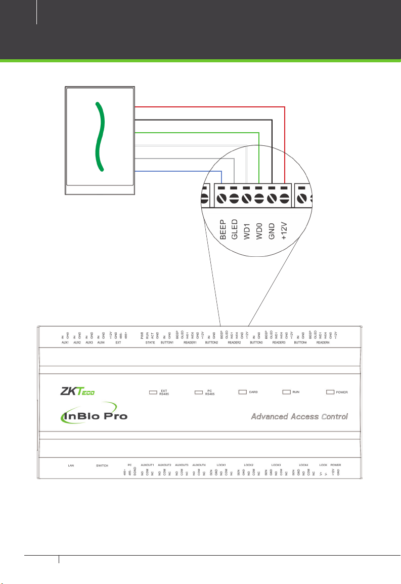
Product PIN Diagram
4 Aux Inputs
State Indicator
#1 Door Card Reader
#1 Door Exit Button
RS485
Fingerprint Reader
#2 Door Card Reader
#2 Door Exit Button
#3 Door Card Reader
#3 Door Exit Button
#4 Door Card Reader
#4 Door Exit Button
4 Lock & Door Sensor
4 Aux Output
DIP Switches
Ethernet Port
Lock Power
InBio Pro Power
LINK LED
ACT LED
SD Card Slot
Figure 1

7
InBio Pro Series Access Control Panels INSTALLATION GUIDE
LED Indicators
LINK Solid Green LED indicates TCP/IP
communication is normal.
Flashing (ACT )Yellow LED indicates
data communication is in progress.
EXT RS485 (TX/RX) Flashing Yellow
& Green LED indicates communication is
in progress.
Flashing (POWER) Red LED indicates
the panel is powered on.
Flashing (RUN) Green LED indicates
that panel is in normal working state.
Flashing (CARD) Yellow LED indicates
that the card is read by the panel.
Figure 2
Figure 3
Figure 4
Figure 5
Figure 7
Figure 6
8
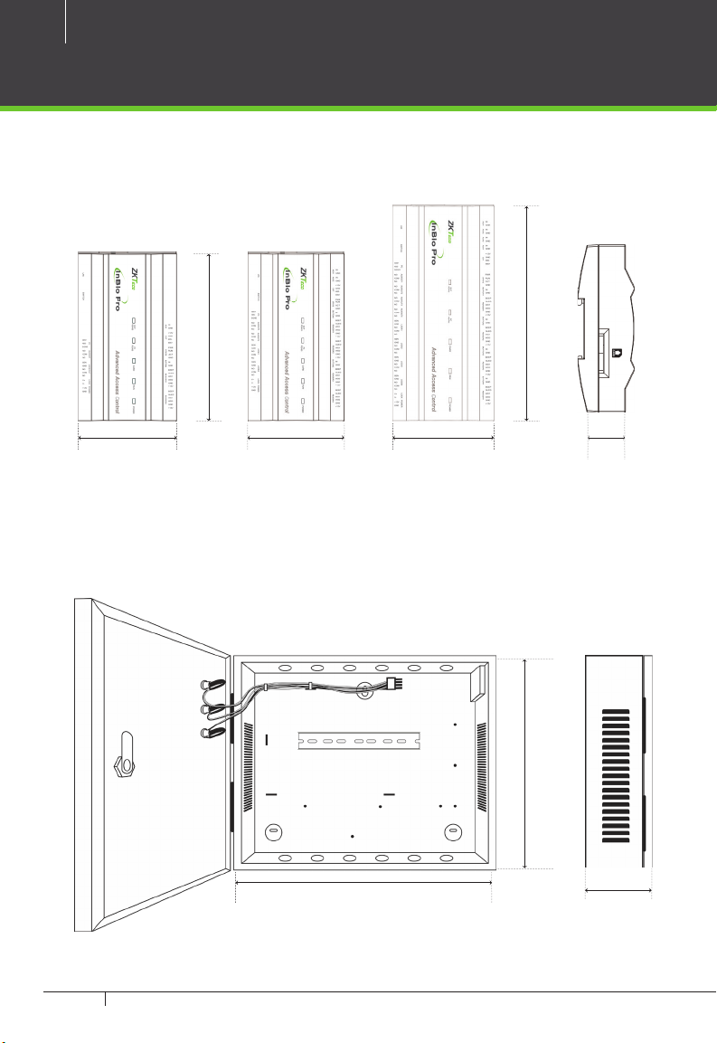
InBio Pro Series Access Control Panels INSTALLATION GUIDE
Product Dimension
Figure 9
InBio160Pro InBio260Pro InBio460Pro
InBio Pro- Metal Cabinet
Figure 8
8.89 in8.89 in
(226 mm)(226 mm)
7.125 in7.125 in
(181 mm)(181 mm)
1.42 in (36 mm)1.42 in (36 mm)
4.17 in (106 mm)4.17 in (106 mm)
4.17 in (106 mm)4.17 in (106 mm)
4.17 in (106 mm)4.17 in (106 mm)
15.7 in (400 mm)15.7 in (400 mm)
13 in13 in
(330 mm)(330 mm)
3.56 in3.56 in
(90.5 mm)(90.5 mm)

9
InBio Pro Series Access Control Panels INSTALLATION GUIDE
Installation of Panel & Cabinet
Cable ConduitCable Conduit
(Punch Hole for cables)(Punch Hole for cables)
Temper SwitchTemper Switch
InBio Pro PanelInBio Pro Panel
Heat Dissipation GrillHeat Dissipation Grill
Power SupplyPower Supply
Backup BatteryBackup Battery
Mounting HolesMounting HolesState IndicatorsState Indicators Inserting Panel to RailInserting Panel to Rail
Mounting RailMounting Rail
We recommend drilling the mounting plate screws into solid wood (i.e. stud/beam). If a stud/beam cannot be
found, then use the supplied drywall plastic mollies (anchors).
Step 1
Pass the cable through holes
Step 2
Mount the Metal Cabinet
Step 3
Insert the InBio Pro Panel as it
shown
Figure 10
Figure 11
1
2

10
InBio Pro Series Access Control Panels INSTALLATION GUIDE
Wiring Legend
Detector Ethernet Cable
IR Sensor
Exit Button Floodlight
Wiegand
Card Reader
Exit Button
Normally Open Lock
Normally Close Lock
Wiegand
Card Reader
12V DC Power Supply
12V DC Power
Figure 12

11
InBio Pro Series Access Control Panels INSTALLATION GUIDE
Power Wiring Diagram
Without Backup Battery
With Backup Battery
Switching Power Supply
Ground
Ground
Switching Power Supply
Figure 14
Figure 13

12
InBio Pro Series Access Control Panels INSTALLATION GUIDE
RS485 Fingerprint Reader Connection
12V DC12V DC12V DC12V DC
ETHERNETETHERNET
1238RS485 Fingerprint Reader
Figure 15
13
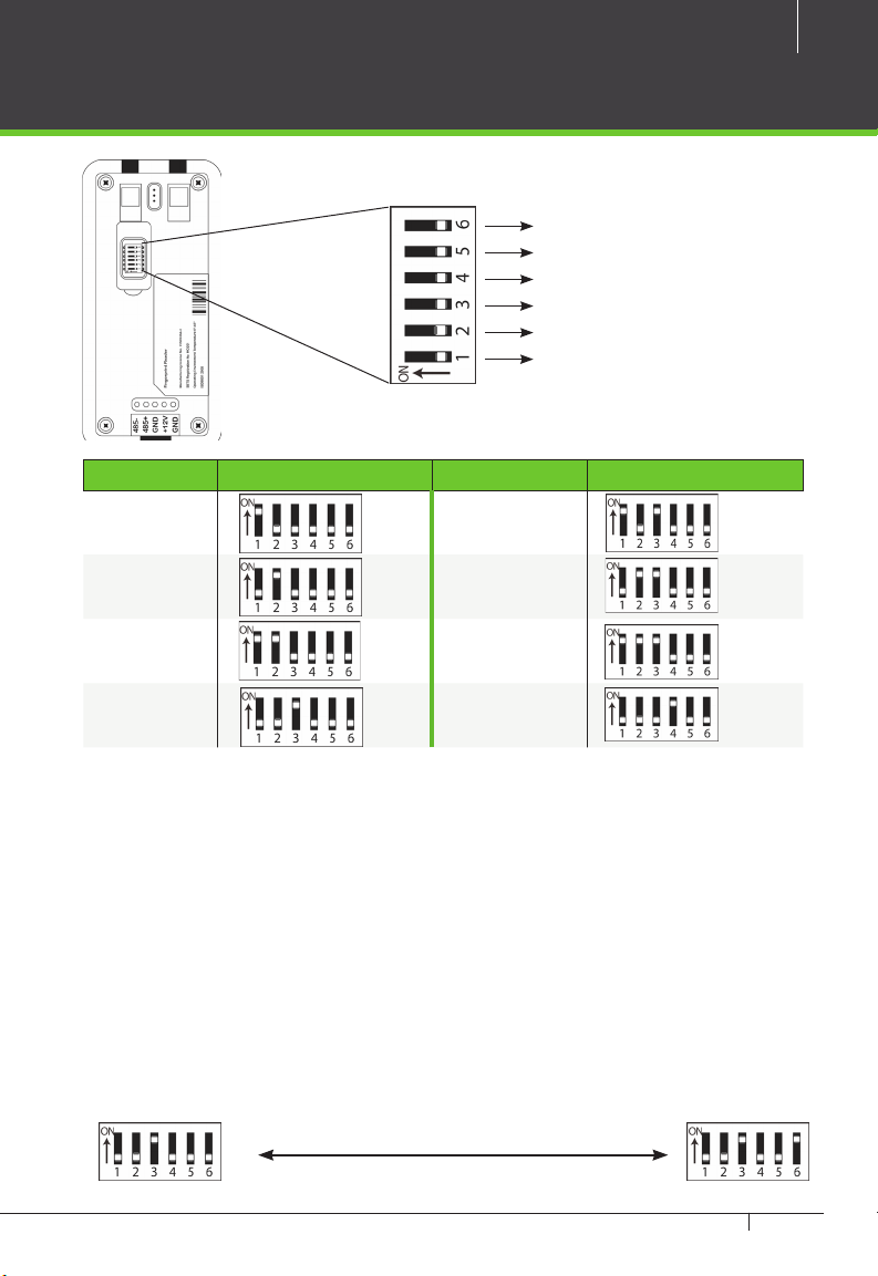
InBio Pro Series Access Control Panels INSTALLATION GUIDE
DIP Switch Setting for RS485 Reader
DIP SwitchDIP Switch
Figure 16
RS485 Terminal Resistance
8
4
2
1
Address Switch Settings Address Switch Settings
1 5
2 6
3 7
4 8
Important Notes
1. There are six DIP switches on the
back of RS485 ngerprint reader,
Switches 1-4 is for RS485 address,
switch 5 is reserved, switch 6 is for
reducing noise on long RS485 cable.
2. Set the odd number for IN reader,
and the even number for OUT reader
(for eg. For two readers for one door-
the RS485 address 1 is for IN reader,
RS485 address 2 is for OUT reader)
3. If RS485 ngerprint reader is pow-
ered from InBio460Pro panel ,the
length of wire should be less than
100 meters or 330 ft.
4. The External RS485 interface can
supply maximum 500mA current,
The RS485 ngerprint reader’s
startup current is 240mA. So InBio-
460Pro only can power two RS485
ngerprint readers.
5. If the cable length is more than
200 meters or 600 ft , the number 6
switch should be ON as below:
Distance: More than 200 metersDistance: More than 200 meters
14
InBio Pro Series Access Control Panels INSTALLATION GUIDE
Wiegand Connection
Wiegand Card Reader
Figure 17
BeeperBeeper
Green LEDGreen LED
Wiegand D1Wiegand D1
Wiegand D0Wiegand D0
GNDGND
DC+(6-14V)DC+(6-14V)

15
InBio Pro Series Access Control Panels INSTALLATION GUIDE
REX Connections
ZK ABK Exit Button
K2 Exit Switch
Separate Power Supply
UnusedUnused
NONO
BUTTONBUTTON
COMCOM
GNDGND
12V DC(+)12V DC(+)
12V DC( - )12V DC( - )
Figure 18

16
InBio Pro Series Access Control Panels INSTALLATION GUIDE
Lock Connection
Connecting a Lock with External to Power Supply
(Dry Contact)
FR107FR107
DiodeDiode
GNDGND
GNDGND
SensorSensor
SensorSensor
12V DC12V DC
Door ContactDoor Contact
ETHERNETETHERNET
Figure 19
-
+

17
InBio Pro Series Access Control Panels INSTALLATION GUIDE
Switching Dry Contact to Wet Contact
Important Notes:
The factory default jumper setting is set as dry mode. If you want to power the
lock from the panel, you must take the following steps:
1. Take apart the cover of InBio460Pro. Push the tab inward (see gure 21)
2. Select the appropriate lock relay and nd its jumpers
3. Take o the jumpers and change to
4. Connect the lock as show in the diagram, (see gure 23 and 24)
Back of InBio460Pro Select one Relay
Default setting
1, 2 - 3, 4
Take o jumpers Jumpers Plug Jumpers
2, 3 - 4, 5
Figure 21
Figure 20

18
InBio Pro Series Access Control Panels INSTALLATION GUIDE
Lock Connection
Normally Open Lock Powered From Lock Terminal
(Wet Contact)
Normally Closed Lock Powered From Lock Terminal
(Wet Contact)
12V DC12V DC
12V DC12V DC
12V DC12V DC
12V DC12V DC
GNDGND
GNDGND
FR107FR107
DiodeDiode
FR107FR107
DiodeDiode
GNDGND
GNDGND
ETHERNETETHERNET
ETHERNETETHERNET
Figure 22
Figure 23
16 or 18 AWG shielded cable recommended
-
+
-
+

19
InBio Pro Series Access Control Panels INSTALLATION GUIDE
Aux. I/O Connection
Aux. Input Connection
Aux. Output Connection
12V DC12V DC
12V DC12V DC
GNDGND
GNDGND
ETHERNETETHERNET
Figure 25
Figure 24
ETHERNETETHERNET

USB USB
USB
USB
Direct connection
To connect InBio Pro Panel with a PC directly, connect both devices with a
straight network cable. As the InBio Pro Panel supports auto MDI/MDIX, it is not
necessary to use a crossover type cable.
CR20E Card Issuer ZK4500 Enrollment reader
ZK4500 Enrollment readerCR20E Card Issuer
ETHERNET
ETHERNET
20
InBio Pro Series Access Control Panels INSTALLATION GUIDE
Ethernet Connection
LAN Connection
Important Notes:
1. Both 10Base-T and 100Base-T are supported
2. This cable distance must be less than 330 ft. (100m)
3. For cable length of more than 330 ft. (100m). use HUB to amplify the signal.
Figure 26
Figure 27
CAT5e or CAT6 ethernet
cable recommended
Other manuals for InBio Pro Series
2
Table of contents
Other ZKTeco Control Panel manuals


Popular Control Panel manuals by other brands


Fagor
Fagor CNC 8040 - MCO-TCO OPTIONS operating manual

Panasonic
Panasonic AV-HS60C4E operating instructions

Prestel
Prestel MFCP-6 user manual

AUDAC
AUDAC DW5066/W User manual & installation guide

Protect America
Protect America Simon XT installation manual

Crow
Crow Runner Series Installation and configuration guide