ZLG CANDTU-400EWGR User manual

Category
Contents
Keywords
CAN-BUS message record Ethernet WIFI
Description
Product User Guide
©2021 Guangzhou ZLG Microelectronics Technology Corp.,Ltd.
CANDTU-400EWGR User Manual
CAN Bus Message Record and Wireless Data Transmission Equipment
UM01010101 1.0.00 Data:2019/03/11
User
Manual

CANDTU-400EWGR
CAN Bus Message Records and Wireless Data Transmission Equipment Series Products
©2021 Guangzhou ZLG Microelectronics Technology Corp.,Ltd.
2
User Manual
Revision History
Version
Date
Description
V1.00
2019/08/18
Created

CANDTU-400EWGR
CAN Bus Message Records and Wireless Data Transmission Equipment Series Products
©2021 Guangzhou ZLG Microelectronics Technology Corp.,Ltd.
1
User Manual
Contents
1. Product Introduction.....................................................................................1
1.1 Product Overview...................................................................................................1
1.2 Features..................................................................................................................1
1.3 Typical Applications................................................................................................2
2. Specifications...............................................................................................3
2.1 Electrical Parameters.............................................................................................3
2.2 Operating Temperature ..........................................................................................3
2.3 Protection Level......................................................................................................3
3. Mechanical Dimensions...............................................................................5
4. Hardware Interfaces.....................................................................................7
4.1 Panel Layout...........................................................................................................7
4.2 Indicators................................................................................................................7
4.3 Button .....................................................................................................................8
4.4 Power Interface ......................................................................................................8
4.5 CAN-bus Interface and DI DO................................................................................9
4.6 Ethernet Interface.................................................................................................13
4.7 SD Card Interface.................................................................................................14
4.8 4G Interface..........................................................................................................14
4.9 GPS Interface.......................................................................................................15
5. Appendix....................................................................................................16
5.1 Network Data Format...........................................................................................16
5.2 CAN Data Frame Format .....................................................................................18
6. Disclaimer..................................................................................................20

CANDTU-400EWGR
CAN Bus Message Records and Wireless Data Transmission Equipment Series Products
©2021 Guangzhou ZLG Microelectronics Technology Corp.,Ltd.
1
User Manual
1. Product Introduction
1.1 Product Overview
It mainly includes: product introduction (overview), product pictures (function
instructions may not be provided), and a detailed list of functions.
In the CAN bus troubleshooting, the biggest difficulty is occasional faults. This makes
engineers or even CAN experts unable to accurately identify the fault cause. For example,
the pitch system of the wind turbine had a CAN data transmission interruption in 72 hours;
the dashboard of a new energy vehicle appeared "blank" once during a 10,000 km drive,
but this could not reoccur; the high-speed train experienced an emergency deceleration
due to abnormal CAN communication during a 2,000 km journey. These occasional
CANFD communication exceptions have frightened engineers like time bombs. If one
CAN bus data recorder is installed on an occasion prone to faults, it is equivalent to a
"black box" to record CAN data, which helps analyze the fault cause.
Guangzhou ZLG Electronics Co., Ltd., as a leading manufacturer of the domestic
CAN bus, has developed CANDTU series products for troubleshooting CAN buses, which
can record CAN messages offline. It can easily complete the message recording and
on-site monitoring of applications such as vehicles, ships, elevators, wind turbines, and
construction machinery.
CANDTU-400 series products are 4-channel CAN bus data recorders with storage,
which can run independently from PC and store CAN message data for a long time, which
helps users analyze and troubleshoot. The recorder can transfer the recorded data to a
PC via an SD memory card on the Ethernet.After format conversion of the raw data, users
can carry out offline analysis and evaluation of the recorded data by using CANoe and
CANScope.
1.2 Features
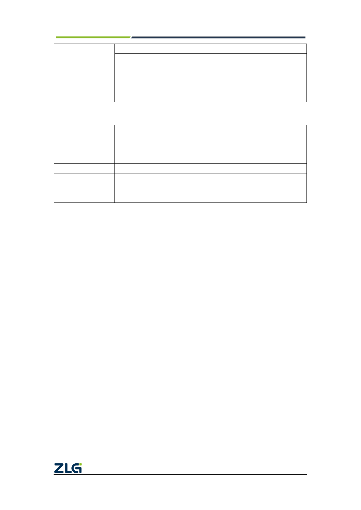
Table 1.1 Product features
CAN channel
Number of channels: four user-configurable CAN channels
Interface type: high-speed CAN
Baud rate: arbitrarily programmable between 5 Kbps and 1 Mbps
Maximum receive data flow: 4,500 frames/s
Surge protection: 1 kV (Class A)
Isolation voltage: 3,500 V
Ethernet Interface
100M/1000M adaptive
Wireless 4G
transmission
Support Unicom, Telecom, Mobile 4G
Digital output
Two digital outputs
Digital input
Two digital inputs
Message recording
and storage
Storage Capacity: supports SD memory cards of a maximum of 64 GB
Storage mode: all storage, timing storage

CANDTU-400EWGR
CAN Bus Message Records and Wireless Data Transmission Equipment Series Products
©2021 Guangzhou ZLG Microelectronics Technology Corp.,Ltd.
2
User Manual
Full mode: rolling record, full stop
Trigger mode: conditional trigger, external trigger
Find and location: Manual time stamping
Data export: supports multiple data formats, such as .frame, .csv, .txt,
and .asc for software analysis
Real-time clock
Built-in rechargeable lithium battery
Continued
Software resources
Supports the general configuration function library, which helps users
develop application programs with VC, VB, Delphi and C++ Builder
Supports the configuration tool CANDTU
Power supply voltage
DC 9 ~ 48V
Power consumption
2.5W
Range of temperature
Operating temperature: -40℃to +85℃
Storage temperature: -40℃to +85℃
External dimension
179mm×131.5mm×50.4mm
1.3 Typical Applications
High-speed train operation fault detection and troubleshooting
Subway train running fault detection and troubleshooting
Train control system operation fault detection and troubleshooting
Wind turbine CAN communication fault detection
Multi-channel CAN communication records and fault analysis for traditional vehicles
and new energy vehicles
Ship CANFD communication fault detection and troubleshooting
Coal mine CAN communication fault analysis
Elevator operation fault detection and troubleshooting
Construction machinery operation fault detection and troubleshooting
Operation detection and troubleshooting of aerospace vehicles and ancillary
equipment

CANDTU-400EWGR
CAN Bus Message Records and Wireless Data Transmission Equipment Series Products
©2021 Guangzhou ZLG Microelectronics Technology Corp.,Ltd.
3
User Manual
2. Specifications
2.1 Electrical Parameters
Table 2.1Electrical parameters
Parameter Name
Conditions
Rating
Unit
Minimum
Typical Value
Maximum
Operating voltage
DC
9
24
48
V
Power consumption
2.04
2.5
5.2
W
2.2 Operating Temperature
Table 2.2Operating temperature
Parameter Name
Rating
Unit
Minimum
Typical
Value
Maximum
Operating
temperature
-40
-
85
℃
Storage
Temperature
-40
-
85
℃
2.3 Protection Level
Table 2.3Protection level-electrostatic discharge immunity test (IEC61000-4-2)
Interface
Test level
Test Voltage (kV)
Test Result
Remarks
Power supply
Level 4
8
Class A
Contact
discharge
CAN bus
Level 4
8
Class A
Contact
discharge
Ethernet
Level 4
8
Class A
Contact
discharge
Buttons,
Indicators
Level 4
15
Class A
Air discharge
Table 2.4Protection level-electrical fast transient pulse group immunity test
(IEC61000-4-4)
Interface
Test level
Test voltage (kV)
Test Result
Remarks
Power
supply
Level 3
2
Class A
Capacitive
coupling
CAN bus
Level 3
1
Class B
Capacitive
coupling
Ethernet
Level 3
2
Class A
Capacitive
coupling
Table 2.5Protection level-surge (impact) test (IEC61000-4-5)
Interface
Test level
Test voltage (kV)
Test Result
Remarks
Power
Level 3
1
Class A
Line-line

CANDTU-400EWGR
CAN Bus Message Records and Wireless Data Transmission Equipment Series Products
©2021 Guangzhou ZLG Microelectronics Technology Corp.,Ltd.
4
User Manual
supply
Level 3
2
Class A
Line-ground
CAN bus
Level 3
1
Class B
Line-line
Level 3
2
Class B
Line-ground
Ethernet
Level 3
1
Class A
Line-line
Level 3
2
Class A
Line-ground
Note: For details, see the attached Electromagnetic Compatibility Test Report.pdf

CANDTU-400EWGR
CAN Bus Message Records and Wireless Data Transmission Equipment Series Products
©2021 Guangzhou ZLG Microelectronics Technology Corp.,Ltd.
5
User Manual
3. Mechanical Dimensions
The mechanical dimensions are shown in the following figure (unit: mm)
Figure 3.1 Host dimensions diagram 1
Figure 3.2 Host dimensions diagram 2

CANDTU-400EWGR
CAN Bus Message Records and Wireless Data Transmission Equipment Series Products
©2021 Guangzhou ZLG Microelectronics Technology Corp.,Ltd.
6
User Manual
Figure 1 Installation method 1
Figure 2 Installation method 2

CANDTU-400EWGR
CAN Bus Message Records and Wireless Data Transmission Equipment Series Products
©2021 Guangzhou ZLG Microelectronics Technology Corp.,Ltd.
7
User Manual
4. Hardware Interfaces
This section describes the hardware interfaces of CANDTU-400 series equipment.
4.1 Panel Layout
Figure 4.1 shows the device panel layout.
Figure 4.1 Panel layout
4.2 Indicators
Table 4.1 LED indicators
Identification
Function
Status
Description
SYS
System running
status indicator
Continuous green light
The device is normal
The red indicator
flashes slowly
Recording is not activated
The red indicator
flashes quickly
SD card abnormal
4G
Indicates 4G status
Continuous green light
The 4G module is waiting for
connection
Green flashing light
The 4G module is in data
transmission
The red indicator is on
The 4G module is abnormal
The indicator is off
The 4G module is not enabled
CAN0、1
CAN2、3
CAN channel
transceiver status
indicator
The indicator is off
The CAN channel is not
activated
Green flashing light
The CAN channel receives data
properly
The red indicator is on
The CAN channel received an
error frame

CANDTU-400EWGR
CAN Bus Message Records and Wireless Data Transmission Equipment Series Products
©2021 Guangzhou ZLG Microelectronics Technology Corp.,Ltd.
8
User Manual
4.3 Button
The device provides a trigger button. The shell is identified as "Trigger". Its function is
to mark the CAN message data, so that the user can locate the data recorded in the SD
card. In addition, this button can be used for firmware upgrade.
Table 4.2 Button functions
Operation
Function
Conditions
Description
Symptom
Stop
recording
Stop storing
CAN message
data
Normal
recording, or
resumed
recording
Hold down the button for
more than 3 seconds and
less than 10 seconds to stop
recording. Then you can
safely eject the SD card
The buzzer beeps
Recover
records
Recover
storage
CAN message
data
Recording
has stopped,
and the card
exists
Short-press the button to
resume recording
Return to the state before
the stop;
The buzzer beeps twice
Once the configuration is
downloaded, the recording
can be resumed
Recording
has stopped
but the card
does not
exist
Reinsert the card to resume
recording
User tag
Mark
CAN message
data
Normal
record
Press the button for more
than 200 ms and no more
than 2s to mark the data.
The REC indicator
flashes once;
The buzzer beeps briefly.
User
upgrade
Upgrade
device
firmware
Power-on
process
Insert the SD card, press
and hold the button, and
power on the device;
Release the button after
three short buzzer beeps
The buzzer makes three
short beeps
Restore
network
parameters
Restore
default
network
parameters
Device
running
process
Hold down the button for
more than 10s, and release
the button
The buzzer beeps long
while the button is
pressed
When the button is
released, the buzzer
beeps four times in a row
4.4 Power Interface
The rated voltage of the power input of the equipment is DC 9-48 V, and the casing is
marked as "DC 9-48V". The physical form of the interface is 5.08 terminals. 错误!未找到

CANDTU-400EWGR
CAN Bus Message Records and Wireless Data Transmission Equipment Series Products
©2021 Guangzhou ZLG Microelectronics Technology Corp.,Ltd.
9
User Manual
引用源。, 错误!未找到引用源。 and 错误!未找到引用源。 list the interface diagram, signal
definition, and interface specifications.
Table 4.3 Power interfaces
Type
Schematic Diagram
5.08 terminal
Table 4.4 Terminal signal definitions
Function
interface
Signal
definition
Signal description
Interface Type
5.08 interface
Power
supply
V+
positive electrode of power
√
V-
negative electrode of power
√
Table 4.5 Power interface specifications
Parameter Name
Conditions
Rating
Unit
Minimum
Typical value
Maximum
Working voltage
DC
9
48
V
Power
consumption
2.5
W
4.5 CAN-bus Interface and DI DO
The device provides four isolated CAN-Bus interfaces. The shell identification is
"CAN0", "CAN1", "CAN2/DO", and "CAN3/DI". The physical form of the interface is the
DB9 terminal. 错误!未找到引用源。, 错误!未找到引用源。 and 错误!未找到引用源。 list
the interface diagram, signal definition, and interface specifications.
Table 4.6 Pin definitions
Type
Schematic Diagram
DB9 terminal

CANDTU-400EWGR
CAN Bus Message Records and Wireless Data Transmission Equipment Series Products
©2021 Guangzhou ZLG Microelectronics Technology Corp.,Ltd.
10
User Manual
Pin definitions
Table 4.7 Signal definitions
Function
Interface
Signal
Definition
Signal Description
Pin Number
CAN0~CAN1
CAN0_L
CAN0 data transceiver differential inverted
signal
2
CAN0_GND
CAN0 isolated ground
3、6
CAN0_H
CAN0 data transceiver differential positive
phase signal
7
CAN_FG
Shielding ground
5
NC
Not connected
1、4、8、9
CAN2
CAN0_L
CAN0 data transceiver differential inverted
signal
2
CAN0_GND
CAN0 isolated ground
3、6
CAN0_H
CAN0 data transceiver differential positive
phase signal
7
CAN_FG
Shielding ground
5
DO0_P
Digital 0 output channel positive
8
DO0_N
Digital 0 output channel negative
4
DO1_P
Digital 1 output channel positive
1
DO1_N
Digital 1 output channel negative
9
CAN3
CAN1_L
CAN1 data transceiver differential inversion
signal
2
CAN1_GND
CAN1 isolated ground
3、6
CAN1_H
CAN1 data transceiver differential positive
phase signal
7
CAN_FG
Shielding ground
5
DI0_P
Digital 0 input channel positive
8
DI0_N
Digital 0 input channel negative
1

CANDTU-400EWGR
CAN Bus Message Records and Wireless Data Transmission Equipment Series Products
©2021 Guangzhou ZLG Microelectronics Technology Corp.,Ltd.
11
User Manual
DI1_P
Digital 1 input channel positive
9
DI1_N
Digital 1 input channel negative
4
Table 4.8 CAN-Bus interface specifications
parameter
Minimu
m
Typical
value
Maximu
m
Unit
Communication baud rate
5k
1M
bps
Number of nodes
110
pcs
Dominant level (logic 0)
CANH
2.75
3.5
4.5
V
CANL
0.5
1.5
2
Recessive level (logic 1)
CANH
2
2.5
3
CANL
2
2.5
3
Differential level
Dominant (logic 0)
1.2
2
3.1
Recessive (logic 1)
-0.5
0
0.05
Maximum withstand
voltage of the bus pin
-18
18
Instantaneous voltage of
the bus
-100
+100
Isolation voltage (DC)
3500
V
Figure 4 Typical network connection of high-speed CAN
The CAN bus adopts balanced transmission. ISO11898-2 stipulates: In the
high-speed CAN, a 120 ohm terminal resistor needs to be connected to the network
terminal node to eliminate signal reflection on the bus and avoid signal distortion. Figure
3.2 shows the high-speed CAN network topology.
The device has a built-in 120 ohm terminal resistance, which can be configured to
turn on or off by using the configuration tool CANDTU. For operation details, see 4.3.1.
Note: The bus communication distance and communication rate are related to the
field application and can be designed according to the actual application and related
standards. The CAN-Bus cable can use ordinary twisted pair, shielded twisted pair or
standard bus communication cable. In long-distance communication, the terminal
resistance value needs to be selected according to the communication distance, cable
impedance and number of nodes.
The device provides two digital outputs. The physical form of the interface is a flange
terminal. 错误!未找到引用源。 and 错误!未找到引用源。 list the interface schematic
diagram, signal definition, and interface specifications.
Table 9 Flange terminal signal definition
Function
Signal
Signal description

CANDTU-400EWGR
CAN Bus Message Records and Wireless Data Transmission Equipment Series Products
©2021 Guangzhou ZLG Microelectronics Technology Corp.,Ltd.
12
User Manual
interface
definition
DO
DO_P
Positive pole of the digital
output channel
DO_N
Negative pole of the digital
output channel
Table 10 DO interface specifications
parameter
Conditions
Minimu
m
Typical
value
Maximu
m
Unit
Contact load
DC 3A, resistive
30
V
Contact load
AC 3A, resistive
250
V
Contact Resistance
DC 1A, 24V
0.1
Ω
Isolation voltage
Valid value
4000
V
设备
输出单元
DO_P
DO_N
用户电源
用电设备
Figure 1 DO network connections
The switch output interface is a relay output type, and the interior is a relay contact.
The output control circuit is not limited by voltage and polarity, and can be 24 V DC or 220
V AC. Since it is a dry contact output, users need an external power supply to supply
power to alarm devices (such as buzzers). 错误!未找到引用源。 shows the connection.
The switch output interface is used to output the alarm signal. Through the
configuration tool, configurable trigger events include record full, CAN bus error, and SD
card status abnormality. In addition, the relay can be configured to be normally open or
normally closed based on user needs.
Note: The DO function only supports the CANDTU-400EWGR device model
The device provides two digital inputs. The physical form of the interface is a flange
terminal. 错误!未找到引用源。 and 错误!未找到引用源。 list the interface diagrams,
signal definitions, and interface specifications.
Table 4.11 Flange terminal signal definition
Function
interface
Signal
definition
Signal description

CANDTU-400EWGR
CAN Bus Message Records and Wireless Data Transmission Equipment Series Products
©2021 Guangzhou ZLG Microelectronics Technology Corp.,Ltd.
13
User Manual
DI
DI_P
Positive pole of the digital input
channel
DI_N
Negative pole of the digital input
channel
Table 11 DI interface specifications
parameter
Conditions
Minimu
m
Typical
value
Maximu
m
Unit
Logic 0 signal
DC
0
3
V
Logic 1 signal
DC
5
24
V
Isolation voltage
Valid value
3750
V
设备
输入单元
DI_P
DI_N
用户电源
开关设备
Figure 2 DI network connections
By using the configuration tool, the switch input interface can be configured as timing
recording mode and analog key-pressing mode.
1) The timing recording mode is used to regularly collect the switching status of external
equipment, such as valve closing and opening, motor start and stop, and contact
connection and disconnection. 错误!未找到引用源。 shows the connection diagram.
2) Simulate button mode can be used to simulate on-board buttons, including message
marking, pause recording, and resume recording.
Note: The DI function only supports the CANDTU-400EWGR device model
4.6 Ethernet Interface
The device provides one Ethernet interface. The physical form of the interface is
RJ45, which realizes the communication between the device and the PC. The interface
100/1000M specification, interface schematic diagram and signal definition are shown in
Table 4.13.
Table 4.12 Ethernet Interface
Type
Schematic Diagram

CANDTU-400EWGR
CAN Bus Message Records and Wireless Data Transmission Equipment Series Products
©2021 Guangzhou ZLG Microelectronics Technology Corp.,Ltd.
14
User Manual
RJ45 terminal
4.7 SD Card Interface
The device provides one SD card interface, which supports a maximum of 64 GB SD
memory card for storing CAN bus message data. The interface adopts a self-locking card
slot, and the SD card can be locked after the card is inserted according to the direction of
the casing logo to prevent accidental falling off during use. When pulling out the card, just
push it inwards to eject the SD card.
The SD card uses the EXT4 file system. Connecting the SD card through a card
reader cannot directly view the SD card data in the Windows system. You need to install a
tool plug-in that supports the EXT file system (for example, Ext2Fsd).
Note: Do not forcibly pull out the card during the device operation; otherwise, it
may cause data loss or damage to the memory card and device exceptions! If
necessary, after powering off the device, open the SD card slot cover, push in
gently and eject the SD card.
4.8 4G Interface
The device provides one 4G interface. Table 4.14 lists the physical form of the
interface.
Table 4.13 4G interface
Type
Schematic Diagram
4G interface

CANDTU-400EWGR
CAN Bus Message Records and Wireless Data Transmission Equipment Series Products
©2021 Guangzhou ZLG Microelectronics Technology Corp.,Ltd.
15
User Manual
4G antenna
Note: The 4G function only supports the CANDTU-400EWGR device model
4.9 GPS Interface
The device provides one GPS interface. The physical form of the interface is
shown in Table 4.15.
Table 4.15 GPS interface
Type
Schematic Diagram
4G interface
GPS antenna
Note: The GPS function only supports the CANDTU-400EWGR device model

CANDTU-400EWGR
CAN Bus Message Records and Wireless Data Transmission Equipment Series Products
©2021 Guangzhou ZLG Microelectronics Technology Corp.,Ltd.
16
User Manual
5. Appendix
5.1 Network Data Format
The CANDTU device supports two network data formats: network data packets and
network data frames.
错误!未找到引用源。 shows the network data packet format, and 错误!未找到引用源。
shows the network data frame format. The two network data formats need to be switched
through the configuration tool.
Network data packets are composed of multiple network data frames, device IDs, and
absolute timestamps.
Figure 5.1 Network packet format
The device ID serial number is added to the header of the network data packet, and
the data part is a specific data message. Each packet of network data packets may
contain different types of packet data. The packet data needs to be obtained after parsing
according to the specific data protocol. 错误!未找到引用源。 shows the message data
protocol.

CANDTU-400EWGR
CAN Bus Message Records and Wireless Data Transmission Equipment Series Products
©2021 Guangzhou ZLG Microelectronics Technology Corp.,Ltd.
17
User Manual
Figure 1 Message data format
Data parsing operation after the network packet is received:
1. Judge and identify network data packets according to the packet header flag
(0xAB) and checksum;
2. Get the device ID;
3. Get the absolute timestamp;
4. Get the data length;
5. The specific message is obtained according to the data length and the message
protocol.
When parsing a specific message in step 5, the checksum of the message can be not
calculated any longer.
Data parsing operation after the network packet is received:
1. Judge and identify network data frames according to the frame header flag
(0xAA) and checksum
2. Get the frame type
3. Parse the specific message content according to the frame type
For the definition of CAN message data format, 错误!未找到引用源。 appendix
below.
Table of contents
Other ZLG Control Unit manuals
Popular Control Unit manuals by other brands

SEA
SEA PRE-GATE manual

Honeywell
Honeywell BA295S installation instructions

A.R.I.
A.R.I. D-020 Installation operation & maintenance

Larson Electronics
Larson Electronics BLG-LED-4REX-131 instruction manual

Faraday
Faraday 8705 INSTALLATION INSTRUCTIONS AND WIRING

Pacbrake
Pacbrake PH5 Powerhalt Programming manual