Zodiac INDIGO User manual

1
Dear Sirs,
Thank you for the confidence you have shown in BARACUDA technology for automatic
pool cleaning. It is thanks to pool professionals that we have become the European and
world leader in the field of hydraulic appliances. This is why we wish to be in even
closer contact with you, the better to respond to your needs and offer you a constantly
improving technical and sales service.
The Indigobook is the technical guide distributed only to pool industry professionals
selling INDIGO
TM
robots by ZODIAC. It supplements the information given to the user
in the technical instructions provided with the appliance.
This information will enable you to give valuable advice to your INDIGO
TM
owning
customers. It will also help you adjust the robot effectively to suit the configuration of
every pool for optimum performance.
The design of ZODIAC appliances has always been oriented to simplicity and reliability.
Please do not hesitate to contact our technical service or to get in touch with our usual
sales contact for further information.
The ZODIAC POOL CARE EUROPE technical and sales team
The ZODIAC product INDIGO™ is made by ZODIAC POOL CARE EUROPE S.A.S.U.

2
CONTENT
1. TROUBLESHOOTING............................................................................................................................................... 3
1.1. THE INDIGO DOESN'T MOVE OR SUCK UP ANY LITTER.............................................................................................. 3
1.2. WALL CLIMBING .................................................................................................................................................... 3
1.3. ROBOT TILTS BACKWARD ...................................................................................................................................... 4
1.4. ROBOT EMERGING ABOVE THE WATER LINE............................................................................................................ 4
1.5. BAD ADHESION TO POOL BOTTOM ......................................................................................................................... 5
1.6. NO MOVEMENT –SUCTION OK ............................................................................................................................... 5
1.7. FILTRATION INEFFECTIVE....................................................................................................................................... 6
2. ASSEMBLY / DISASSEMBLY .................................................................................................................................. 7
2.1. TOOLS REQUIRED ................................................................................................................................................... 7
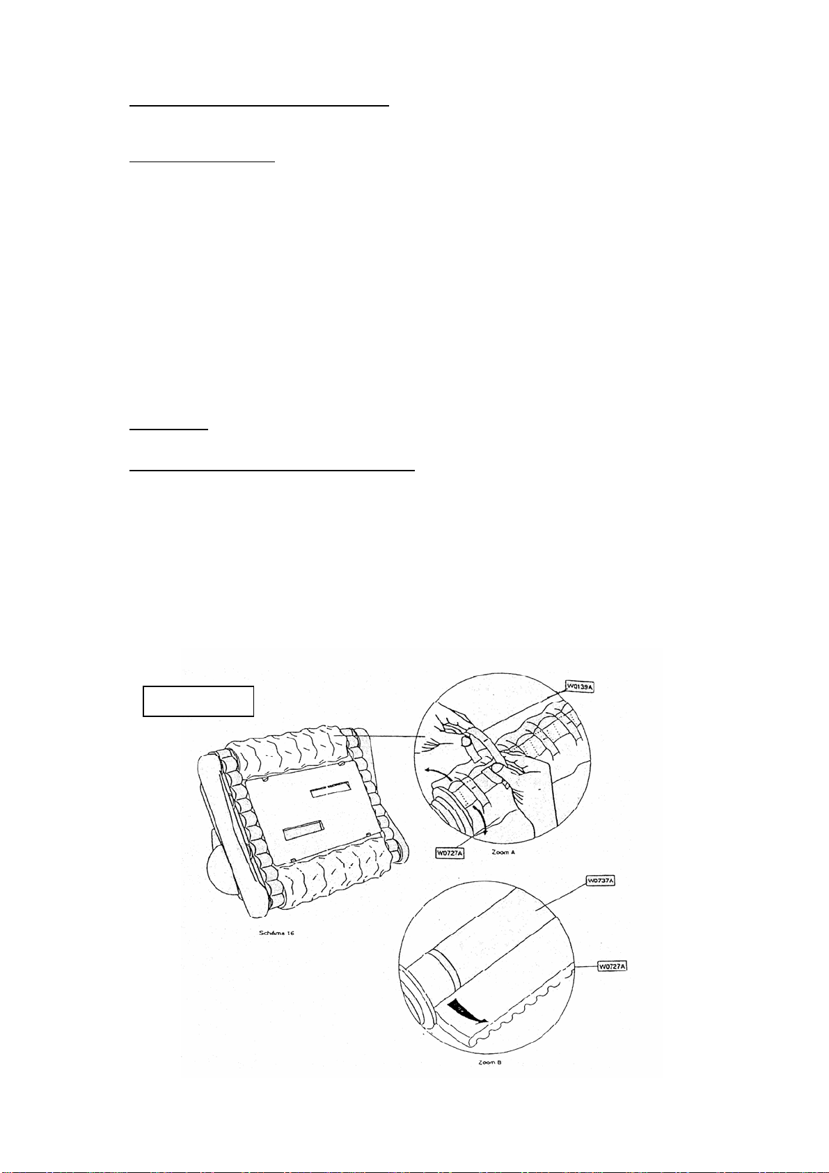
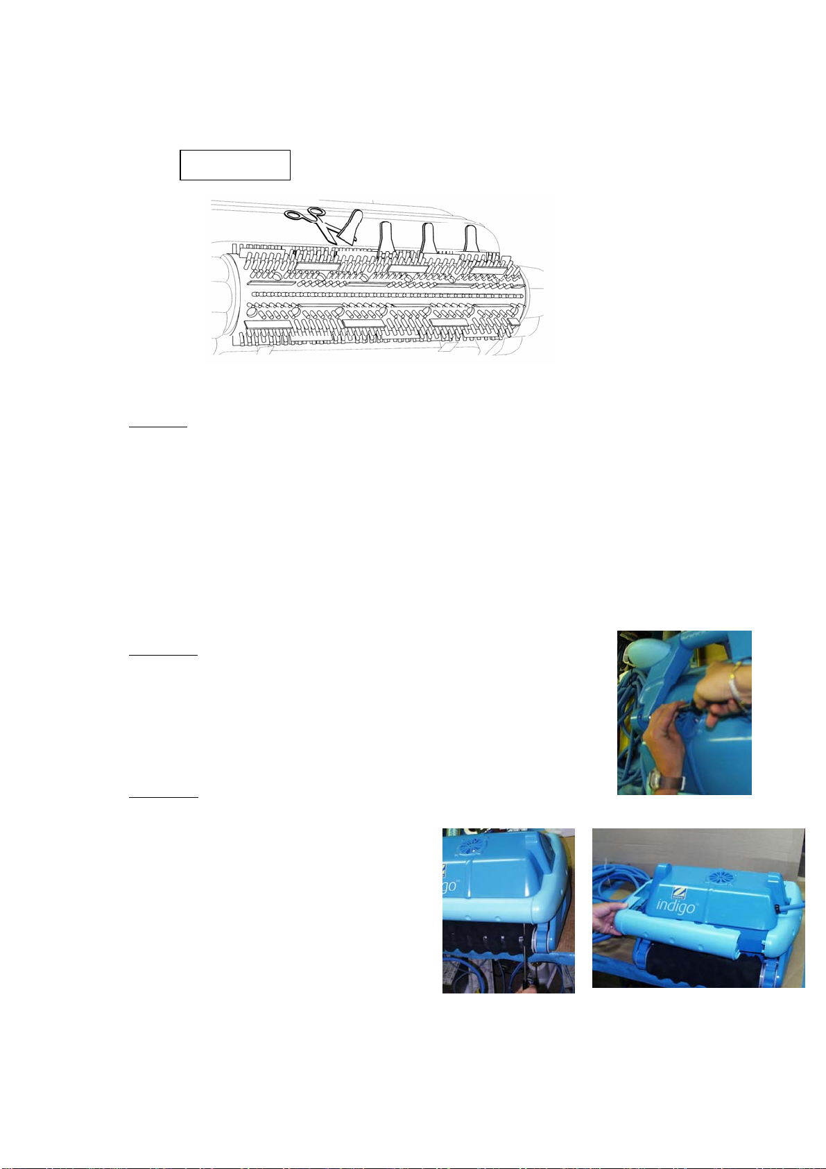
2.2. BRUSHES ................................................................................................................................................................ 7
2.2.1. Your robot is fitted with foam pads............................................................................................................... 7
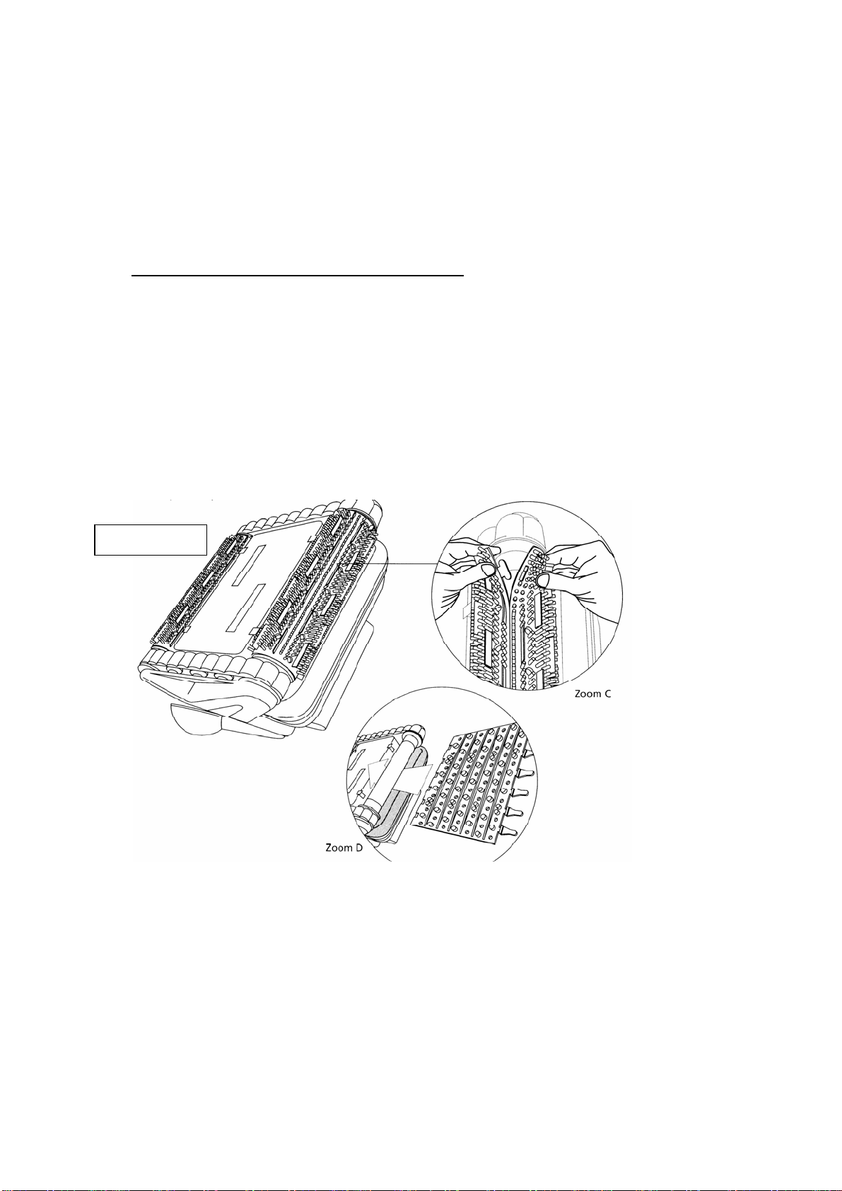
2.2.2. Your robot is fitted with rubber brushes....................................................................................................... 8
2.3. ROTOR.................................................................................................................................................................... 9
2.4. HANDLE.................................................................................................................................................................. 9
2.5. BUMPER.................................................................................................................................................................. 9
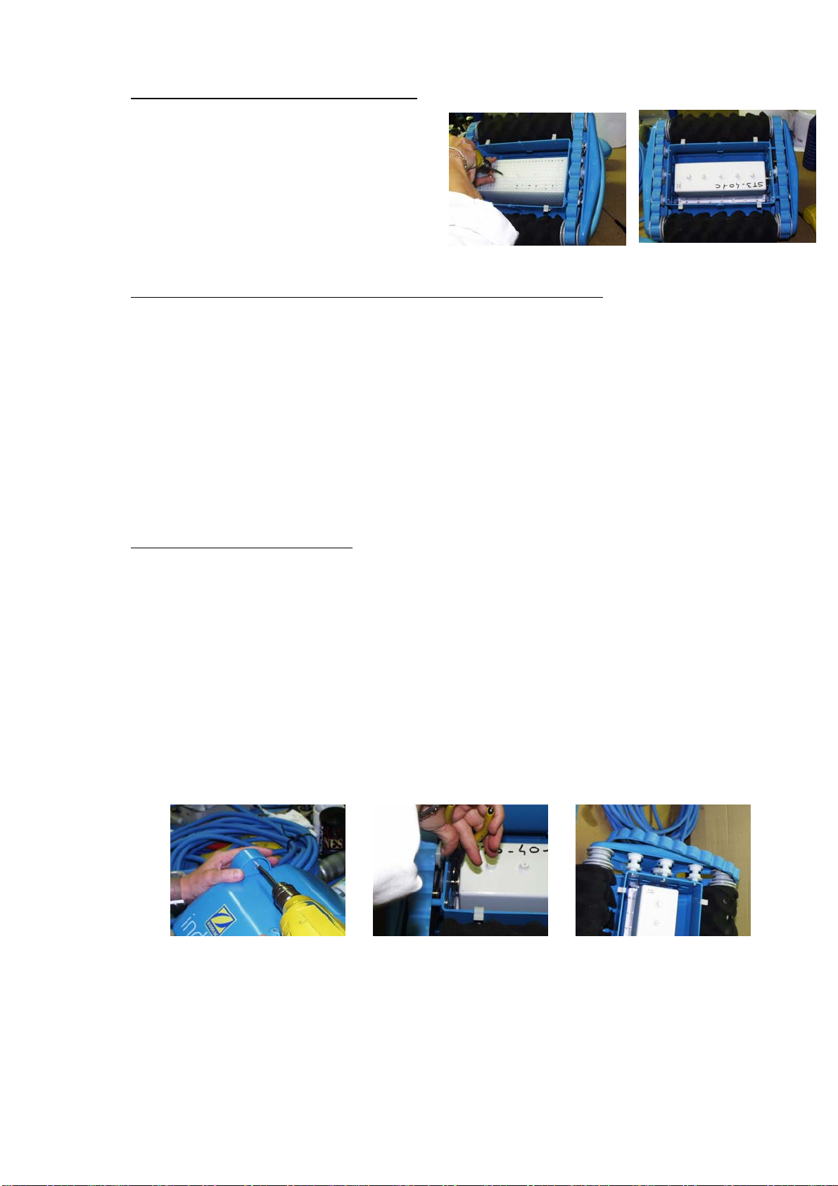
2.6. MOTOR UNIT PROTECTIVE SCREEN ...................................................................................................................... 10
2.7. TRACK PLATE ON TRACTION SIDE (SIDE OPPOSITE CABLE)................................................................................... 10
2.7.1. Removal of the Track Plate......................................................................................................................... 10
2.7.2. Track........................................................................................................................................................... 11
2.7.3. Drive Roller – Transmission Belt – Track .................................................................................................. 11
2.7.4. Track Plate.................................................................................................................................................. 12
2.7.5. Belt Tension Jacks....................................................................................................................................... 12
2.7.6. Belt Settings................................................................................................................................................. 12
2.7.7. Fitting the Traction Track Plate (side opposite cable) ............................................................................... 12
2.8. CABLE SIDE TRACK PLATE................................................................................................................................... 13
2.8.1. Removing the Cable-Side Track Plate ........................................................................................................ 13
2.8.2. Track Guide Roller Track ........................................................................................................................... 14
2.8.3. Track Plate.................................................................................................................................................. 14
2.8.4. Plate Assembly (cable side) on the Housing............................................................................................... 14
2.9. MOTOR UNIT ........................................................................................................................................................ 14
2.9.1. Removing the Motor Unit............................................................................................................................ 15
2.9.2. Replacing the Motor Unit ........................................................................................................................... 15
3. TECHNICAL DIAGRAMS....................................................................................................................................... 17
3.1. GENERAL DIAGRAM ............................................................................................................................................. 17
3.2. TROLLEY (W1210A)............................................................................................................................................ 18
3.3. MOTOR UNIT (W1287A)....................................................................................................................................... 19
3.4. CONTROL UNIT (W1207A) ................................................................................................................................... 21
3.5. HOUSING (W1286A) ............................................................................................................................................ 22
3.6. MOTOR HOUSING COVER (W0684A) .................................................................................................................... 23
3.7. FLEXIBLE LEAD KIT (W1313A) ............................................................................................................................ 24
3.8. PUMP MOTOR (W1290A)...................................................................................................................................... 25
3.9. GEARED TRACTION MOTOR (W1166A)................................................................................................................. 26
3.10. FILTER HOLDER (W1201A) .................................................................................................................................. 27
4. PARTS LIST............................................................................................................................................................... 28
5. CONTACT INDIGO TECHNICAL DEPARTMENT........................................................................................... 30

3
1. TROUBLESHOOTING
1.1. THE INDIGO DOESN'T MOVE OR SUCK UP ANY LITTER
You've switched on and tried to start Indigo but it doesn't do anything.
POSSIBLE CAUSES CHECKS AND CORRECTIVE ACTION
- The red indicator light doesn't come
on when you start a cycle (Turbo or
Perfect).
- The red light comes on but the robot
won't start.
ÆPlug in another electrical appliance to check the
plug.
ÆCheck the robot cable is properly connected to
the control unit.
1.2. WALL CLIMBING
Indigo goes forwards and backwards without any problems but has difficulty climbing the
walls or can't climb them at all.
POSSIBLE CAUSES CHECKS AND CORRECTIVE ACTION
- The filter bag is clogged with litter, scale or
flocculents.
- There are microscopic algae on the sides
of the pool.
- The belts have become slack.
- The belts and tracks are slipping (fatty
bodies present).
ÆEmpty and clean the filter bag with clear
water. Use soap if necessary.
ÆCheck the quality of the water and apply any
necessary treatment; lower the pH slightly
(remove the unit from the water prior to shock
chlorination).
ÆIf necessary, clean the sides with a hand
broom.
ÆTighten or replace the belts (never add
grease or silicone).
ÆClean the tracks, belts and pulleys with C
essence or similar.

4
1.3. ROBOT TILTS BACKWARD
The robot tilts backwards at the foot of the sidewall.
POSSIBLE CAUSES CHECKS AND CORRECTIVE ACTION
- The rotor is broken or obstructed by
foreign bodies.
- The robot's suction system is
malfunctioning.
ÆRemove any hairs, pieces of cloth or foreign
bodies obstructing the rotor or replace the rotor if it
is broken.
ÆBring the robot up to just below the water level
and check for backflow at the turbine screen outlet.
If the pump isn't working, ask your supplier for the
necessary after-sales service.
1.4. ROBOT EMERGING ABOVE THE WATER LINE
The robot is emerging above the waterline and is sucking in air.
POSSIBLE CAUSES
CHECKS AND CORRECTIVE ACTION
- The robot is too light because there's
air in it.
- The water level is too high, which
forces the robot to come into contact
with the edging.
- The lining is furred or the pH of the
water is low.
ÆTurn the robot over to expel the air from the filter
bag and press the foam pads.
ÆLower the water level.
ÆAdjust the pH and clean the waterline.

5
1.5. BAD ADHESION TO POOL BOTTOM
The robot doesn't stay properly on the bottom of the pool, and even wants to pull away from the
bottom.
POSSIBLE CAUSES
CHECKS AND CORRECTIVE ACTION
- The robot is too light because there's
air in it.
- The rotor is broken or obstructed by
foreign bodies.
- The robot's suction system is
malfunctioning.
ÆTurn the robot over to expel the air from the filter
bag and press the foam pads.
ÆAdd more ballast.
ÆRemove any hairs, pieces of cloth or foreign
bodies obstructing the rotor or replace the rotor if it
is broken.
ÆBring the robot up to just below the water level
and check for backflow at the turbine screen outlet.
If the pump isn't working, remove the motor unit and
ask your supplier for the necessary after-sales
service.
1.6. NO MOVEMENT –SUCTION OK
The Indigo won't go forwards or backwards, but the suction system is working properly (backflow at
turbine outlet).
POSSIBLE CAUSES
CHECKS AND CORRECTIVE ACTION
- The belts are slack.
- The beta pin has come out of its housing
and fallen into the motor unit protective
screen or into the robot.
- The belts and tracks are slipping (fatty
bodies present).
- The traction motor is malfunctioning.
ÆTighten the belts or replace them.
ÆChange and refit the pin.
ÆClean the tracks, belts and pulleys with C
essence or similar.
ÆAsk your supplier for the necessary after-sales
service.

6
1.7. FILTRATION INEFFECTIVE
The filtration system is not working properly or the rotor is throwing up litter.
POSSIBLE CAUSES
CHECKS AND CORRECTIVE ACTION
- The filter bag is clogged with litter, scale or
flocculents.
- The rotor is broken or obstructed by foreign
bodies.
- The filter bag has come unstitched and
may even be torn.
- The filter bag has not been properly fitted:
the base is incorrectly positioned.
- A foreign body (small stone, branch, leaf,
etc.) is stuck in the suction holes in the filter
holder.
- The black flap valves are deformed or
missing.
ÆEmpty the filter bag and clean it with clear
water and, if necessary, soap.
ÆRemove any hairs, pieces of cloth or foreign
bodies obstructing the rotor or replace the rotor
if it is broken.
ÆChange the filter bag.
ÆReposition the filter bag elastic or replace
the bag if the elastic has become too slack.
ÆClear the filter bag inlet.
ÆReplace the black flap valves.

7
2. ASSEMBLY / DISASSEMBLY
2.1. TOOLS REQUIRED
∗No-bounce mallet
∗Cordless drill/screwdriver
∗Flat-nose pliers
∗Wrench ∅19 (packing gland)
∗Automatic stripping pliers
∗"Ogival head" oblique cutting pliers
∗Lever-operated grease pump
∗Set of screwdrivers for slotted-head screws
∗Set of screwdrivers for cross-recessed screws
2.2. BRUSHES
2.2.1.Your robot is fitted with foam pads.
We recommend that you change the foam pads after one season's use.
It is essential to change them if their surface becomes smooth or worn
Turn the robot upside down and:
Open out the pads to reveal the foam attachment clips, then lift the clips up (using a lever if
necessary) and remove them; be careful not to open them too wide. (Zoom A).
Diagram 16

8
−Place the edges of the foam pads face up and position all the clips in their slots without securing
them.
−When all the clips are correctly positioned in their slots, open them out slightly and press them in
around the pad holder with the guide mark in the centre of the clips positioned at the foam pad
join.
−Tighten the pads, keeping the guide mark in the correct place.
2.2.2. Your robot is fitted with rubber brushes.
We recommend that you change the foam pads after 2 season's use.
−Turn the robot upside down, taking care not to rest it on the float arms (diagram 17).
−Spread the edges of the rubber brush to unfasten the retaining strips, then remove the worn brush
(Zoom C).
−Position the replacement brushes with the small fine bristles outside; to do this, thread the part
without a strip between the green bumper and the brush holder (for the robot to give of its best,
the strips must be positioned correctly (Zoom D).
Diagram 17

9
−Thread the strips into their respective slots and pull them very gently so that the heels go through
to the other side of the slots
−With a pair of scissors, cut strips at least 5 mm from the heel (diagram 18).
2.3. ROTOR
a) Disconnect the rotor from the control unit.
b) Holding the flow guide remove the four 2.9 X 9.5 (W0351A) self-tapping screws.
c) Remove the rotor (using a screwdriver as a lever).
d) Remove the flow guide to clear access to the rotor.
e) Refit the rotor.
f) Refit the flow guide and the four screws. (Make sure the rotor isn't touching the flow guide.)
2.4. HANDLE
The handle can be removed from the housing to avoid scratches if you need
to take out the track plates.
To remove the handle, unscrew the two M5X35 and the spreaders.
2.5. BUMPER
The bumper needs to be removed before removing the plates.
a) – b) Position a large flat-bladed screwdriver
between the bumper and the housing, using
the brush holder as a lever.
c) Repeat this step in the opposite corner.
d) Remove the 2 halves assembled (1 front, 1
lateral)
a-b d
Diagram 18

10
2.6. MOTOR UNIT PROTECTIVE SCREEN
a) Free the filter holder.
b) Remove the two 3.5 X 13 self-tapping
screws.
c) Remove the moor unit protective screen
and then the ballast weights. (The robot
comes with a single ballast weight on
the cable side.)
2.7. TRACK PLATE ON TRACTION SIDE (SIDE OPPOSITE CABLE)
When you remove the traction-side plate you can change the following parts:
The track
The track guide roller
The brush holders
The track plate
The drive roller
The belts
The 'S' and 'C' shaped belt tension jack
2.7.1. Removal of the Track Plate
Before removing the plates you have to remove the bumpers, the handle and motor unit protective
screen.
You can then start to remove the plate.
a) Remove the self-tapping screw at the top of the plates.
b) Turn the robot upside down. Then use flat-nose pliers to remove the Beta pin from the traction
motor axle.
c) Remove the track opposite the plate.
d) Remove the three 3.9 X 25 self-tapping screws and the washers.
e) Carefully free the plate and the brush holders.
a b c

11
d e
You can now access all the traction components:
2.7.2. Track
Take out the old track and fit the new one.
2.7.3. Drive Roller – Transmission Belt – Track
You have to take out all the moving parts of the plate in order to change any one of them.
Assembly:
a) Undo the belt tension jacks and turn them to face the bottom of the plate.
b) Put the track on the plate.
c) Place the drive roller on the plate and place a belt in each groove. The location of the belt is
given by the 'S' or 'C' belt tension jack.
d) Place the brush holder in the plate housing. Place the belt in the appropriate groove in the
brush holder such that it is opposite the brass roller of a tension jack.
e) Place the other brush holder in its housing. Make sure you place the belt in the right groove
without disturbing the first brush holder.
b c d
With the robot fully assembled, adjust the belt tension jack (see para. 2.7.6).

12
2.7.4. Track Plate
Remove all the parts of the plate.
a) Put the belt tension jack on the plate shaft. The screw must be tight on the plate side.
b) Place the track roller in the plate shaft.
c) To fit the moving parts, follow the procedure described in the previous paragraph.
2.7.5. Belt Tension Jacks
Remove the belt tension jack and fit a new one in its place. Adjust the fit in the centreline of the belt
and also the tension.
2.7.6. Belt Settings
To check belt tensions are correct, pres them in A or B: the deformation [E] should be equal to ± 5mm
and should offer resistance to traction. If not, readjust the tension:
a) Undo the 2 locking screws.
b) Press on the tension jack to readjust belt tension.
c) Hold the tension jack down and retighten the screws.
IMPORTANT: The two tension jacks are set separately and should be set strictly one after the
other.
2.7.7. Fitting the Traction Track Plate (side opposite cable)
All the parts should be placed on the track plate before assembly on the robot. The unit should be
turned upside down.
a) Start by placing the top of the plate (facing the handle).
b) Push the plate against the housing and insert the drive roller on to the motor shaft.
c) Hold the track plate against the housing and insert the brush holder spindle into the
opposite plate; then insert the other brush holder.
d) Turn one of the brush holders to align the hole in the drive roller with the hole in the motor
shaft (use a small screwdriver to align the holes).
e) Place the Beta pin.
f) Insert the 3.9X25 screws with their washers.
g) Place the track on the brush holders.
h) Turn the unit over and insert the screw on the top of the plate.

13
a b c
e f
Fit the handle (lowest float on the cable side), the motor unit protective screen and the bumpers to
complete the assembly of the cleaner.
2.8. CABLE SIDE TRACK PLATE
When you remove the plate, you can change the following parts:
The track
The track guide rollers
The track plate
2.8.1. Removing the Cable-Side Track Plate
Before removing the track plate, remove the bumper and the motor protective screen.
You can now start to start removing the track plate.
a) Remove the self-tapping screw in the top of the track plate.
b) Remove the track.
c) Remove the three 3.9 X 25 self-tapping screws and their washers.
d) Carefully free the track plate, making sure the brush holders are on the traction-side track
plate.
a b c
You can now access numerous parts that you may need replacing:

14
2.8.2. Track Guide Roller Track
Replace the old part with a new one and place the complete plate on the housing.
Make sure you fit the roller in the right direction.
2.8.3. Track Plate
Remove all the parts of the old plate. The carefully take out the brass spindle with pliers, making sure
you don't make any scratches.
With a small hammer, fit the new brass spindle to the new plate.
Fit all the moving parts to the plate.
Assemble the complete plate on the housing.
2.8.4. Plate Assembly (cable side) on the Housing
All the parts can be assembled on the track plate. You will need to turn the unit over.
a) Start by placing the top of the plate (handle side). Then fit the track plate on to the housing.
b) Fit the 3.9 X 25 self-tapping screw and its washer.
c) Place the brush holder spindle into the track plate, and then the other one.
d) Insert the other two 3.9x25 screws and their washers.
e) Fit the track on to the brush holders.
f) Turn the unit over and insert the screw belonging to the top of the plate.
a c e
Fit the handle (lowest float on the cable side), the motor unit protective screen and the bumpers to
complete the assembly of the robot.
2.9. MOTOR UNIT
To remove the motor unit you will need to take out the bumpers, the handle, the motor unit protective
screen, the plate opposite the cable and then the plate on the cable side.
Important: do not open the motor unit during the guarantee period.

15
2.9.1. Removing the Motor Unit
a) Remove the cable clamp (press and pull).
b) Turn the robot upside down and remove the four 5x12 screws.
c) Carefully take out the motor unit with its cable.
d) Cut the cable as close as possible to the stuffing box.
a b c d
2.9.2. Replacing the Motor Unit
The motor units are supplied with a set of parts including a stuffing box, a seal, terminals and two
screws.
a) Cut the floating sheath to 90 mm and strip the cable back to 45 mm:
b) Pass the cable through the housing and fit the stuffing box on to the cable.
c) Strip each wire to reveal 5 mm.
d) Crimp the 4 terminals with a pair of crimping pliers.
e) Make a spot tin solder on each crimped terminal.
f) Place the O-ring on the cover.
g) Connect the wires to the cover (the colours are shown on the cover).
h) Connect the robot and do a performance test.

16
b c d
e f g
i) Fill the cover connection with grease (ref. W0265A).
j) Position the stuffing box on the cover. The cable should be able to move freely in the
stuffing box.
k) Insert the two 4.2x13 screws.
l) Use a 19mm spanner to tighten the stuffing box until the seal is flush with the top of the
cover.
m) Refit the rotor on to the pump motor shaft.
n) Insert the motor unit into its housing. Take the excess cable to the outside of the housing.
o) Secure the motor unit to its housing with the four 5x12 screws. Make sure the rotor is
properly centred in the flow guide and not rubbing.
p) Refit the cable clamp to the housing.
i k l
To complete the assembly, first fit the cable-side track plate (see para. 2.8.4.), then the plate on side
opposite the cable (see para. 2.7.7). Fit the handle (lowest float on the cable side), the motor unit
protective screen and the bumpers.

17
3. TECHNICAL DIAGRAMS
3.1. GENERAL DIAGRAM

18
3.2. TROLLEY (W1210A)

19
3.3. MOTOR UNIT (W1287A)

20
N° reference Description Quantity
1 W1124A
2 MOTOR HOUSING ABS
1
2 W1592A
PLOT ADHESIVE
4
3 W1166A
DRIVEN MOTOR ASSEMBLY
1
4 W0128A
JOINT 18,4X2,7 SIDE PLMOT
3
5 W0126A
NUT P SIDE PLATE RUNN/ROT
1
6 W1302A
RED WIRE L=235 0,75 MT2003
1
7 W1303A
BLUE WIRE L=235 0,75 MT2003
1
8 W1290A
PUMP MOTOR
1
9 W0127A
JOINT 19X2 SIDE PLATE MOT
1
10 W0129B
NUT K SIDE PLATE PUMP MOT
1
11 W0325A
BRASS NUT M4
4
12 W0326A
BRASS RING M4
8
13 W1193A
INBOARD CARD
1
14 W0116A
CABLE TERMINAL
4
15 W0360A
SCREW VP 50 X 12
4
16 W0122A
JOINT 29,3X3,6 MOT.HOUS.L
1
17 W0343B
MOTOR HOUSING LOCKING SYS
1
18 W0025A
SCREW VT TCL POZI 4,2X13
2
19 W1116A
ACCES. BAG MOTOR HOUSING LOCKI
1
20 W0072A
ANTI-MOISTURE BAG
2
21 W0684B
SET MOTORBLOC COVER SWY
1
22 W0331A
RING M3 A2
40
23 W0542A
SCREW VM TCL POZI 3X20 A2
20
24 W0071A
JOINT 225X3 MOTOR HOUS.CO
1
25 W0541A
NUT INDESS M3 A2
20
32 W1524A
LEST INOX
1
Table of contents
Other Zodiac Vacuum Cleaner manuals

Zodiac
Zodiac RE 42 Series User manual

Zodiac
Zodiac ALPHA iQ iAquaLink CONTROL User manual

Zodiac
Zodiac CX40 User manual

Zodiac
Zodiac ARCO ARCOMAX User manual

Zodiac
Zodiac RE 42 Series User manual

Zodiac
Zodiac VortraX TRX 7500 iQ User manual

Zodiac
Zodiac vortex 2 User manual

Zodiac
Zodiac RV 5480 iQ User manual

Zodiac
Zodiac Duo-X iAquaLink CONTROL DX4050 iQ User manual

Zodiac
Zodiac VORTEX-PRO VX40 User manual