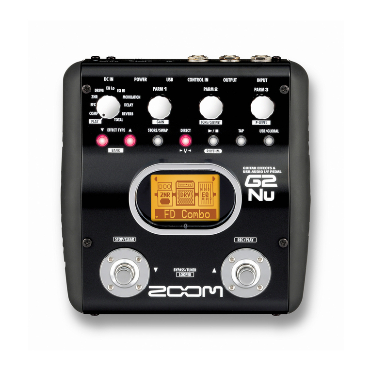
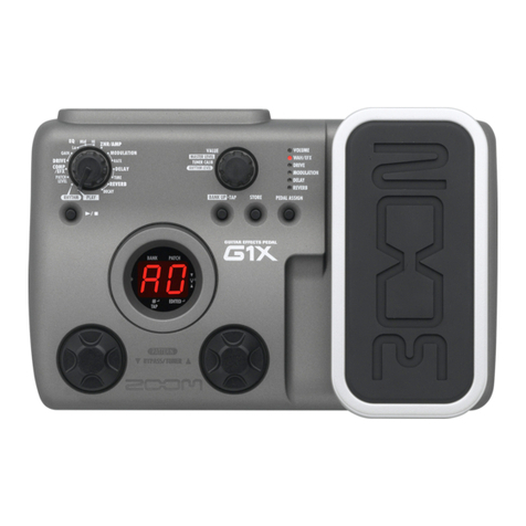
Zoom g9.2tt User manual


- 2 -
Contents
Specifications ........................................................................................................................................... 3
Function Test ............................................................................................................................................ 5
Tube Adjustment Specification............................................................................................................... 17
Back Up User’s Data .............................................................................................................................. 24
Recovering the Factory Default ............................................................................................................. 26
Circuit Check Specifications .................................................................................................................. 27
Circuit Diagram ...................................................................................................................................... 28
Exploded view ........................................................................................................................................ 43
Parts List ................................................................................................................................................ 44
Spare Parts Order List ............................................................................................................................ 51
Spare Parts Order Sheet ..........................................................................................................................56
Supplement 1: G9.2tt optical sensor problem..........................................................................................57
Supplement 2: G9.2tt PEDAL SW Adjustment specifications................................................................61
Importance: Harness Fixing.....................................................................................................................63

-3-
Specifications
Number of effect types 106 types
Number of effect modules 10 simultaneously usable modules
Patch memory User area : 5 patches x 20 banks = 100 (read/write enabled)
Preset area : 5 patches x 20 banks = 100 (read only)Total: 200
patches
Sampling frequency 96 kHz
A/D conversion 24-bit, 64-times oversampling
D/A conversion 24-bit, 128-times oversampling
Signal processing 32-bit
Frequency response 20 Hz - 40 kHz +1.0 dB, -3.0 dB (10 kilohm load)
Display 2-digit 7-segment LED display
16-digit 2-line backlit LCD
Inputs Guitar input Standard monaural phone jack
Rated input level: -10 dBm
Input impedance: 1 megohm
AUX input Mini phone jack (stereo)
Rated input level: -10 dBm
Input impedance: 10 kilohms
External Return Standard mono phone jack
Rated input level: -10 dBm/+4 dBm (switchable)

-4-
Outputs
Line output Standard monaural phone jack x 2
Rated output level: -10 dBm/+4 dBm (switchable)
Maximum output level: +19 dBm (into load impedance of 10
kilohms or more)
Output impedance: 1 kilohm or less
Headphone output Standard stereo phone jack
Rated output: 60 m W (into 32-ohm load), 20 m W (into 300-ohm
load)
Output impedance: 47 ohm
External Send Standard mono phone jack
Rated output level: -10 dBm/+4 dBm (switchable)
Tube circuitry 12AX7 x 2
Control connectors MIDI OUT, MIDI IN
USB interface
PC interface 16-bit (record/play, stereo)
Sampling frequencies 32 kHz, 44.1 kHz, 48 kHz
Power requirements 15 V AC, 1.5 A (from supplied AC adapter AD-0012)
Dimensions 235 (D) x 595 (W) x 85 (H) mm
Weight 5.5 kg
• 0 dBm = 0.775 Vrms
• Design and specifications subject to change without notice.

-5 -
Function Test
After the G9.2tt is assembled, the following inspections and settings should be made.
* Equipment required
· AC voltage meter (audio analyzer would be better)
· IHF-A filter (audio analyzer might include it)
· Oscillator
· AC adapter (AD-00012)
· Cables
●Set up before start up Test Mode.
* Adjust both [GAIN SW] (SW200) of OUTPUT and [GAIN SW] of EXT LOOP in -10 dBm.
* Adjust [OUTPUT LEVEL] (VR200) in MAX.
* Adjust both [TUBE] knob (VR201) of ENERGIZER and [BOOST] knob (VR202) of
ENERGIZER in 0 (turn counterclockwise extremely).
* Adjust [TUBE] knob (VR701) of ACCELERATOR in 5 (center) and [SOLIDSTATE] knob
(VR703) of ACCELERATOR in 5 (center).
1. Starting built-in inspection program.
Connect the AC-adapter.
(1)Turn on the "Power SW" while holding [AMP SELECT SYSTEM] key(SW5) and [EXIT]
key(SW19).
Or TP1 of the main PCB connect to the GND before power on. And then power will be turn on, the
set is running as Test Mode.
*AC adapter must be used AD-0012.
(2)After turning on the power, 7SEG LED will be displayed as [8.8.] and LCD, all of the SW, LED
will be ON.
*There is no sound comes out from OUTPUT in this status.
*To make sure that there is no broken or any no dark LED was found.
*After power turned on, the tube will be warm and bright.
(3)When any key will be pressed, the system will be start to DSP Download test mode.
This is the test for Test mode program downloading to the DSP.
This test methodology is comparing with the data which was written and the data which was read.
If in the case of successfully, LCD will be displayed as [DSP DOWNLOAD OK].
If in the case of fail, LCD will be displayed as [DSP DOWNLOAD NG]. If in this case all of the
testing after that will be ignored.
After holding display for 1sec, the LCD comes up all segments again, and then DSP can do a
signal processing.
(De-Emphasis and Emphasis circuit are working in this status.)
*After this the sound which is added from [INPUT] and [AUX IN] comes out from all [OUTPUT ]
(PHONE, L/MONO, R terminal).
When any key will be pressed, all LCD and LED will be off and then the system will be into
another test mode.

2. GAIN SW check
Following the operation “1.”, input sin wave (440Hz/-20dBm) to [INPUT] jack and monitor the
output from [OUTPUT] jack (L/MONO, R) with speakers and oscilloscope.
Make sure that output level changes by switching [-10dBm] and [+4dBm]. Then, output from
[Phones] jack doesn’t change.
*Refer to “Circuit Check Specifications” about the specs of output.
3. OUTPUT LEVEL check
Turn right [LEVEL] volume.
Input audio signal to [AUX IN] jack.
Make sure that outputs level from [PHONE] jack gradually changes by turning around the
[LEVEL] volume of output.
*Insert 32 ohm load.
*Make sure output level changes smoothly by turning volume knob.
*Refer to “Circuit Check Specifications” about the specs of output.
4. VERSION, REVISION, and CRC32 check
Press the [CHANNEL A] key (SW12), and make sure that the [CHANNEL A] key lights up.
Make sure that the LCD is displayed [G9 v1.01 R9031 CRC : 3D78B445] 4/18 present
Press the [CHANNEL B] key (SW13), and make sure that the [CHANNEL B] key lights up.
Make sure that the LCD is displayed [G9F v1.07 R8011 CRC : B2FF05EA].
However, this numbers are indicated only right after flash writing, and this numbers change if
some function like EX PEDAL setting or All Initialize is carried out.
4/18 present
*When it comes and there is no writing information (the contents of FLASH are empty), LCD is
displayed [Empty].
5. DIAL/VOLUME check
Turn the knob (DIAL/VOLUME) in the following table.
Make sure that the indications “01 ->02 -> 03 ... ->Fd ->FE ->FF” appear on the 7segment LED
display when the dial is turned clockwise, and that “FF ->FE ->Fd ... 02 -> 01 -> 00” when turned
anticlockwise.
And the LCD display is changed by every turning those knobs.
Table1. DIAL/VOLUME LCD display
DIAL/VOLUME LCD
[TYPE](SW30) TYPE
[PARM 1](SW31) PARM1
[PARM 2](SW32) PARM2
[PARM 3](SW33) PARM3
[PARM 4](SW34) PARM4
[AMP TYPE](SW35) AMP TYPE
[GAIN](VR1) GAIN
[LEVEL](VR2) LEVEL
[BASS](VR3) BASS
[MIDDLE](VR4) MIDDLE
[TREBLE](VR5) TREBLE
[PRESENCE](VR6) PRESENCE
-6 -

-7 -
6. SEND / RETURN check
Input sin wave (440Hz/-20dBm) to [INPUT] jack and [RETURN] jack, and monitor the output
from [OUTPUT] jack (L/MONO, R) with speakers and oscilloscope.
Then, insert to [RETURN] jack and pull from [RETURN] jack, and make sure that the LCD
display indicates [RETURN plugged].
Press the [PEDAL1 SETTING] key, and this key lights up red and the LCD display indicates
[PEDAL1 SETTING TUNER IN/RETURN]. Besides, by pushing the key repeatedly, the
7segment LED displays [tn], [rt] alternately.
When the 7segment LED displays [tn], input sound of [INPUT] jack is outputted from
[SEND] jack.
Then, make sure output sound changes by selecting [EXT LOOP] GAIN SW.
When the 7segment LED displays [rt], input sound of [RETURN] jack is outputted from
[SEND] jack.
Then, make sure output sound doesn’t change by selecting [EXT LOOP] GAIN SW.
7. DSP-MUTE check
Press the [AMP SELECT SYSTEM] key (SW5).
Make sure the [AMP SELECT SYSTEM] key lights red, and LCD is displayed [AMP
SEL/SYSTEM DSP MUTE].
Then, no sound comes L/MONO jack from [INPUT] jack.
By pushing key repeatedly, 7segment displays [on], [oF] alternately.
*The sound from [AUX IN] jack will be no change.
8. SDRAM check
Press the [BYPASS TUNER] key (SW15).
Make sure the [BYPASS TUNER] key lights red, and LCD is displayed [BYPASS/TUNER
SDRAM].
< delay check >
Input sin wave (440Hz/-20dBm) to [INPUT] jack and monitor the output from [OUTPUT] jack
(L/MONO, R) with speakers and oscilloscope.
*The output sound from [AUX IN] does not change.
Make sure that the delayed signal is output from the [L/MONO OUTPUT] jack and left channel of
[AUX IN] jack.
(Delay time is 0.5 seconds)
9. FLASH check
Press the [PAGE] key (SW17).
Make sure the [PAGE] key lights red, and LCD is displayed [PAGE].
Device check of FLASH is performed.
After a device check, if it is OK, LCD is displayed [Flash Write OK] and 7segment LED is
displayed [ok].
When a device check is not able to be checked, or there is fault, it is displayed [Flash Write NG].
*Make sure that there is no defect on the sound (abnormal noise .etc)
-8 -
10. ANALOG-MUTE check
Press the [STORE/SWAP] key (SW16).
Make sure that the [STORE/SWAP] key lights red, and LCD is displayed [STORE/SWAP
ANALOG MUTE].
The 7segment LED turns [on] and [oF] by pressing the [STORE/SWAP] key.
When the 7segment LED turns on, sound from [PHONE] jack, [L/MONO] jack, [R] jack, and
[SEND] jack are extremely low.
*Make sure that there is no defect on the sound (abnormal noise .etc)
11. USB-MUTE (SW) check
Press the [EXIT] key (SW19)
Make sure that the [EXIT] key lights red, and LCD is displayed [EXIT USB MUTE].
The 7segment LED turns [on] and [oF] by pressing the [EXIT] key.
*Make sure that there is no defect on the sound (abnormal noise .etc)
12. DIRECT-MUTE check
Press the [PEDAL2 SETTING] key (SW20).
Make sure that the [PEDAL2 SETTING] key lights red, LCD is displayed [PEDAL2 SETTING
DIRECT MUTE].
The 7segment LED turns [on] and [oF] by pressing the [STORE/SWAP] key.
When the 7segment LED turns on, output sound from [PHONE] jack is lower than
ANALOG-MUTE.
*The output sound is smaller than ANALOG-MUTE, during DIRECT-MUTE on.
*The output sound from [SEND] jack doesn’t change.
*Make sure that there is no defect on the sound (abnormal noise .etc)
13. SW/LED check
When press the key in the following table2, the pressed Key lights green.
Make sure that the indications [green -> red -> orange -> light off -> green -> red …] appear on
the press the key in the following table when it pressed repeatedly.
* Only [COMP] key (SW1), below all switches turn on if pressing that key.
Table2. SW LCD display
SW LCD
[COMP](SW1) COMP
[WAH/EFX](SW2) WAH/EFX
EXT LOOP (SW614) EXT LOOP
[ZNR](SW6) ZNR
[PRE-AMP](SW9) PRE-AMP
[EQ](SW4) EQ
[CABINET](SW7) CABINET
[MOD/EFX2](SW10) MOD/SFX
[DELAY](SW8) DELAY
[REBERB](SW11) REVERB
[TOTAL/FUNCTION](SW3) TOTAL/EFX CHAIN

-9 -
14. MIDI LOOPBACK check
Connect MIDI cable to [MIDI IN] and [MIDI OUT] (J401)
PUSH [HOLD MANUAL BANK↓] FOOT SW (SW22).
[HOLD MANUAL BANK↓] LED lights red.
LCD displays [MIDI LOOPBACK]. Confirmation of data transmission will be done.
If transmission is OK, LCD displays [MIDI LOOPBACK Success], 7 segment LED displays [ok].
Otherwise, LCD displays [MIDI LOOPBACK 00 timeouted], 7 segment LED displays [nG].
15. LCD CONTRAST check
Push [HOLD BYPASS/TUNER] FOOT SW (SW24).
[HOLD BYPASS/TUNER] LED lights red.
LCD displays [LCD CONTRAST 0123456789ABCDEF].
Check deepness of LCD contrast.
7 segment LED displays [01]-[04]. [01] presents most pale, [04] presents most deep, respectively.
16. CH A/B FUNCTION1 (SW) check
Press the [CH A/B FUNCTION1] FOOT SW (SW26).
Make sure that the [CH A/B FUNCTION1] LED lights green, and LCD is displayed [CH A/B
FUNCTION1].
The [CH A/B FUNCTION1] LED repeats [green -> red -> orange -> light off -> green -> red …]
by pressing the [CH A/B FUNCTION1] FOOT SW.
*Make sure that there is no defect on the sound (abnormal noise .etc)
17. TAP FUNCTION2 (SW) check
Press the [TAP FUNCTION2] FOOT SW (SW 628).
Make sure that the [TAP FUNCTION2] LED lights green, and LCD is displayed [TAP
FUNCTION2].
The [TAP FUNCTION2] LED repeats [green -> red -> orange -> light off -> green -> red …] by
pressing the [TAP FUNCTION2] FOOT SW.
*Make sure that there is no defect on the sound (abnormal noise .etc)
18. WAH/EFX1 (SW) check
Press the [WAH/EFX1] FOOT SW (SW21).
Make sure that the [WAH/EFX1] FOOT SW lights red, and LCD is displayed [TUBE
ENERGIZER].
The 7segment LED turns [on] and [oF] by pressing the [WAH/EFX1] FOOT SW.
*Make sure that there is no defect on the sound (abnormal noise .etc)
-10 -
19. INPUT CIRCUIT NOISE check
Push [PRE-AMP] FOOT SW (SW23)
[PRE-AMP] key lights red.
LCD displays [GAIN +60].
About this check, adjust [TUBE] of ACCELERATOR, [SOLID STATE] of ACCELERATOR,
[TUBE] of ENERGIZER, and [BOOST] of ENERGIZER to 5.
Make sure that noise level increases.
When 7 segment LED displays [on], DSP has +60dB gain and increase white noise of [OUTPUT]
jack (PHONE, L/MONO, R jack) and [SEND] jack sound.
By pushing key repeatedly, 7 segment displays [on], [oF] alternately, and at the same time DSP
gain will be on/off.
20. PRE EMPHASIS check
Push [MOD/EFX2] FOOT SW (SW25)
[MOD/EFX2] key lights red.
LCD displays [PRE EMPHASIS].
By pushing key repeatedly, 7 segment displays [on], [oF] alternately.
* When 7 segment displays [on], PRE-EMPHASIS is on by DSP
21. DE EMPHASIS check
Push [DELAY] FOOT SW (SW27).
[DELAY] key lights red.
LCD displays [DE EMPHASIS].
By pushing key repeatedly, 7segment displays [on], [oF] alternately.
* When 7 segment displays [on], DE-EMPHASIS is on by DSP
22. REVERB (SW) check
Press the [REVERB] FOOT SW (SW 629).
Make sure that the [REVERB] LED lights red, and LCD is displayed [TUBE ACCELARATOR].
By pushing key repeatedly, 7segment displays [on], [oF] alternately.
*The output sound doesn’t change by this operation.
*Make sure that there is no defect on the sound (abnormal noise .etc)

23. EX PEDAL1 check
The 7segment LED is displayed EX PEDAL’s AD value if the PEDAL is moved.
Make sure that this EX PEDAL’s AD value is the same as below table and LCD displayed
[PEDAL2-V].
*MIN : raise EX PEDAL this side.
*MAX : lower EX PEDAL till that contacts gum lightly.
Table3. Expression pedal values
Expression pedal Values
MIN(raise) 07 or more
MAX(down) E0 to F9
Pushed all the way PEDAL SW ON
Make sure that difference between MIN and MAX is 60 or more in hex and this value doesn’t
decrease if EX PEDAL is pressed down.
Adjust of Trimmer potentiometer (VR600).
Carry out the EX PEDAL1 setting.
Make sure that the LCD displays [PEDAL2 ON] by pressing down the EX PEDAL stronger, and
[PEDAL2 ON] disappears by stopping pressing down that pedal.
If AD value is read right after [PEDAL2 ON] disappeared, [PEDAL2-V] is displayed again.
24. The trimmer potentiometer adjustment (VR 600)
Open the BOTTOM COVER.
With the EX PEDAL fully down, and adjust the value to the range of [EE] to [F2] by rotating the
trimmer potentiometer (VR 600) on the FOOT1 PCB (PCB-0158A). Back side of PCB is
displayed as [Pedal L Adjust].
*If the value is less than [EE], adjust the value to max.
* Use a Precision minus driver (Within 2mm in diameter).
25. PEDAL setting
Turn on the power holding the [PEDAL1 SETTING] key, and the indication [PDL Calibration
PEDAL1…min] appears on the LCD. With the EX PEDAL fully raised, press the
[STORE/SWAP] key, and the indication [PDL Calibration PEDAL1…MAX] appears on the
7segment LED.
And the EX PEDAL fully down and then lift your foot off the pedal, then press the
[STORE/SWAP] key.
And the unit returns to the play mode after the indication [ok] appears on the LCD.
After this setting, make sure that the EX PEDAL’s AD value again.
26. Weighting adjustment
Like the right figure, set a balance on the setting
point after making the EX PEDAL’s AD value
minimum. Add a weight to the balance till the EX
PEDAL starts to move. Then adjust the scale to range
of 350g to 500g (QC = 350g to 700g) by hexagon
socket head screw in the unit.
-11 -

-12 -
27. EX PEDAL2 / Z PEDAL check
1.
The 7segment LED is displayed vertical AD value of EX PEDAL2 if the PEDAL is moved
vertically.
Make sure that this AD value of EX PEDAL is the same as below table and LCD displayed
[PEDAL1].
*MIN : raise EX PEDAL this side.
*MAX : lower EX PEDAL till that contacts gum lightly.
Expression pedal Values
MIN(raised) 07 and more
MAX(down) E0 to F9
Pushed all the way PEDAL SW ON
Make sure that difference between MIN and MAX is 60 or more in hex and this value doesn’t
decrease if EX PEDAL is pressed down.
Adjust of Trimmer potentiometer (VR500) on the FOOT1 PCB (PCB-0158A).
Carry out the EX PEDAL2 setting. Back side of PCB is displayed as [Pedal R Adjust].
Make sure that the LCD displays [PEDAL1 ON] by pressing down the EX PEDAL2 stronger,
and [PEDAL1 ON] disappears by stopping pressing down that pedal.
If AD value is read right after [PEDAL1 ON] disappeared, [PEDAL1] is displayed again.
2. The 7segment LED is displayed horizontal AD value of Z PEDAL if the PEDAL is swung
horizontally.
Make sure that this AD value of Z PEDAL is the same as below table and LCD displayed
[PEDAL2-H].
Expression pedal Values
MIN(left) 07 and more
MAX(right) 90 to EA
Make sure that difference between MIN and MAX is 60 or more in hex and this value doesn’t
decrease if Z PEDAL is swung to right.
Adjust of Trimmer potentiometer (VR601) on the FOOT1 PCB (PCB-0158A). Back side of
PCB is displayed as [Pedal_3D Adjust].Carry out the EX PEDAL2 setting.
If the Lock arm is raised the Z PEDAL is steadied.
*Make sure the Z PEDAL doesn’t swing horizontally, and then the Lock arm doesn’t come
down.
28. Adjustment Trimmer potentiometer (VR500 / VR601)
Open the BOTTOM COVER.
1.
With the EX PEDAL2 fully down vertically, and adjust the value to the range of [EE] to [F2]
by rotating the trimmer potentiometer (VR 500) on the FOOT1 PCB (PCB-0158A). Back side
of PCB is displayed as [Pedal R Adjust].
*If the value is less than [EE], adjust the value to max.
2.With the Z PEDAL fully swing to right, and adjust the value to the range of [E0] to [E5] by
rotating the trimmer potentiometer (VR 601) on the FOOT1 PCB (PCB-0158A). Back side of
PCB is displayed as [Pedal_3D Adjust].
*If the value is less than [E0], adjust the value to max.

29. PEDAL setting
Turn on the power holding the [PEDAL2 SETTING] key, and the indication [PDL Calibration
PEDAL2-V…min] appears on the LCD. With the EX PEDAL2 fully raised, press the
[STORE/SWAP] key, and the indication [PDL Calibration PEDAL2-V…MAX] appears on the
LCD.
And the EX PEDAL2 fully down and then lift your foot off the pedal, then press the
[STORE/SWAP] key, and the LCD is displayed [PDL Calibration PEDAL2-V…min] after the
LCD is displayed [PDL Calibration ok] a few seconds.
Raise the lock arm and Z PEDAL is locked. Press the [STORE/SWAP] key after the Z PEDAL
swing to right extremely and the LCD is displayed [PDL Calibration PEDAL2-H…MAX].
Lower the lock arm and Z PEDAL is unlocked. Then the Z PEDAL swing to right extremely, and
press [STORE/SWAP] key again.
And the unit returns to the play mode after the indication [PDL Calibration ok] appears the LCD.
After this setting, make sure that the EX PEDAL and Z PEDAL’s AD value again.
30. Weighting adjustment
Like the right figure, set a balance on the setting
point after making the EX PEDAL2’s AD value
minimum. Add a weight to the balance till the EX
PEDAL starts to move. Then adjust the scale to
range of 350g to 500g (QC = 350g to 700g) by
hexagon socket head screw on the back of EX
PEDAL2.
31. Restoring Factory Defaults
Turn on the [POWER] SW while holding down the [STORE/SWAP] key (SW16), and the
indication [All Initialize? Y: STORE N: EXIT] appears on the LCD.
Then press the [STORE/SWAP] key once more.
Make sure that the LCD displayed [All Initialize Factory Revert..] and these dots go on and off.
Then LCD displayed [Complete!], and initialization is carried out and the system starts up in “Play
Mode”.
*If [EXIT] key is pressed, the system starts up in not All Initialize but Play Mode
32. Sound check 1
Turn on the [POWER] and the 7 segment LED displayed [U0], [WAH/EFX1] LED lights red, and
[CH A/B FUNCTION1] LED lights green.
Then, Input sin wave (440Hz, -10dBm) and monitor its output sound by speaker or oscilloscope.
Make sure this output sound is distortion sound and doesn’t include abnormal noise, and this
output sound isn’t abnormal sound.
-13 -

-14 -
33. ACCELERATOR check
Turn the [SOLOD STATE] knob and the [TUBE] knob counterclockwise extremely, and output
sound from all [OUTPUT] jacks will be muted.
Turn the [SOLID STATE] knob clockwise, and output sound from all [OUTPUT] jacks will be
louder.
Turn the [SOLID STATE] knob counterclockwise again, and turn the [TUBE] knob clockwise,
and output sound from all [OUTPUT] jacks will be distorted and louder.
This distortion increase rapidly when the guide of knob comes up to around 8.
*The LCD display, the 7segment LED, and all LEDs are not change by turning [TUBE] knob and
[SOLID STATE] knob.
*The output sound of [SEND] jack doesn’t change.
*The output sound changes smoothly by turning the [VOLUME].
*The output sound comes from [AUX IN] jack never changes by turning any knobs.
*Refer to Check Spec regarding to output sound specification.
34. ENERGIZER check
Input sin wave (100Hz, -10dBm) and monitor its output sound by speaker or oscilloscope.
Make sure that when the [BOOST] knob will be turned right, the low frequency sound and
middle high range frequency sound will be increased from [OUTPUT] (L/MONO, R terminal).
Input sin wave (440Hz, -10dBm) and monitor its output sound by speaker or oscilloscope.
Make sure that when the [TUBE] knob will be turned right, the distortion of sound will be
increased from [OUTPUT] (L/MONO, R terminal).
*All of the display will be no change even though either [TUBE] or [BOOST] will be turned.
*The sound comes from [AUX IN] will be no change even though either [TUBE] or [BOOST]
will be turned.
*Refer to Test Specification regarding to the output sound.
35. Sound check 2
Press the [BANK ↓] SW (SW22) twice and [DELAY 4] SW once, and the 7segment LED displayed
[b8], [DELAY 4] LED lights red, and [CHA/B FUNCTION1] LED lights green and [TAP
FUNCTION2] LED blinks to orange.
.
Then, Input sin wave(440Hz, -10dBm) and monitor its output sound by speaker or oscilloscope.
Make sure this output sound is rotary sound and doesn’t include abnormal noise, and this output
sound isn’t abnormal sound.
If this output sound is normal, hit the unit’s bottom to a desk a few times with a sound inputting.
Repeat this operation again by a headphone (impedance : 32Ω).
36. EX PEDAL check
Press the [BANK ↑] SW (SW24) twice and the [WAH / EFX 1] SW once after the 35 operation,
and the 7segment LED displayed [U0], [WAH / EFX 1] LED lights red, and [CH A / B
FUNCTION 1] LED lights green.
Lower the EX PEDAL 1, and make sure output volume becomes max when the EX PEDAL’s AD
value is MAX.
Raise the EX PEDAL 1 this side, and make sure output volume becomes mute when the EX
PEDAL’s AD value is MIN.
Then make sure this output sound doesn’t include abnormal noise, and this output sound isn’t
abnormal sound, and this output sound changes smoothly when the EX PEDAL1 is moved.

-15 -
37. EX PEDAL 2 check
In the same patch as the 36 operation, set the EX PEDAL 1 and the Z PEDAL max.
First set the Z PEDAL min, make sure that output sound’s frequency is higher than that by one
octave after setting the Z PEDAL max.
Then make sure this output sound doesn’t include abnormal noise, and this output sound isn’t
abnormal sound, and this output sound changes smoothly when the Z PEDAL is moved
38. Z PEDAL check
In the same patch as the 36 operation, set the EX PEDAL 1 and the Z PEDAL max.
First swing the Z PEDAL to right extremely, make sure that output sound’s frequency is higher
than that by one octave (output sound is higher than input sound by two octave).
Then make sure this output sound doesn’t include abnormal noise, and this output sound isn’t
abnormal sound, and this output sound changes smoothly when the Z PEDAL is moved
39. TUNER check
Long press the [HOLD BYPASS/TUNER] FOOT SW (SW24).
Make sure that the TUNING MODE.
<TUNING check>
Input sin wave (440Hz/-10dBm) to [INPUT] jack
Make sure that the 7segment LED displayed [A8], and output is through sound.
Then press the [HOLD BYPASS/TUNER] FOOT SW once more.
Make sure that the returned Play mode.
40. USB interface operation check
1) Connect the unit to PC with USB cable.
2) Start up USB inspection software.
3) In the BYPASS mode, Input sin wave (440Hz/-10dBm) to [INPUT] jack and monitor the
waveform on PC.
4) Output sin wave (440Hz/-10dB) from PC, monitor the output from [OUTPUT] jack (L/MONO,
R, Phones) with speakers and oscilloscope.
*Make sure there are no defects (abnormal noise, output trouble, etc…)
*Refer to “How to use USB inspection software” about the how to use inspection software.
41. Stability
Put the G9.2tt on a surface plate, and push it diagonally.
Make sure that there is no remarkable space (less than ±0.7 mm is acceptable).

-16 -
42. Factory default setting
Set the knobs and switch as follows:
OUTPUT VOLUME Center
All EFFECT VOLUME Turn anticlockwise till limit
All ENERGIZER VOLUME Turn anticlockwise till limit
TUBE VOLUME OF ACCELERATOR Adjust to 5 (center)
SOLID STATE VOLUME OF ACCELERATOR Adjust to 5 (center)
GAIN SW (both OUTPUT and EXT LOOP) -10 dBm
EX PEDAL (both 1 and 2) MAX(contact with the gum)
Z PEDAL Move to left till limit
Lock arm raise
POWER OFF
If the unit was operated, carry out the All Initialize function for certain before shipment.

-17-
Tube Adjustment Specification
1. Overview
This specification describes the method to adjust differences due to characteristics of
tubes.
2. ACCELERATOR (Input side) adjustment
There are two methods of adjustment. The first is the adjustment that only the
ANALOG PCB is used for, and the second is the adjustment carried out after the unit
is assembled. Choose the method which is convenient methods as the case may be.
2.1 In the case of adjust only the ANALOG PCB
2.1.1 Measurement system
Connect the ANALOG PCB and measurement equipment as below.
●Connect the ANALOG PCB and TUBE-ACC PCB
(CNA_ACC-CNB_ACC).
●Connect CN7B, CN401A, CN402B, and CNA_ACC_TUBE to the
measurement jig with harnesses.
●Connect to GUITAR INPUT (J200) on the ANALOG PCB and an
analyzer or an oscillator.
●Connect an analyzer to ANALOG PCB and the measurement jig.
Don’t connect harnesses which are not described because they are needless and may
encourage to mistake.
Refer to figure 1, figure 2, and figure 3 for details.
D166 ANALOG PCB
Oscillator
or
Analyzer
jig for D166 ACCELERATOR adjustment
AC
ADAPTOR
(AD-0012)
Audio Analyzer
CN7B
CN402B
CN401A
CNA_ACC_TUBE
TP5
ACC
ch2
J200
GUITAR
D166 TUBE-ACC
CNB-ACC CNA-ACC ch1
Figure 1 block diagram of measurement

-18-
Figure 2 G9.2tt ANALOG PCB
TP5 ACC
CN7B
CN401
CN402B
CNA_ACC_TUBE
CNA_ACC
CNB_ACC
J200

-19-
Figure 3 TP5 ACC (magnified picture near adjustment trimmer)
2.1.2. Measurement and adjustment
Carry out measurement and adjustment according to below sequence.
●assemble a measurement system according to block diagram (figure 1).
*CAUTION: There is no switch, and power is turned on when connect an
AC adaptor and the power JACK.
●Input sin wave (440Hz, -40dBm) to the INPUT JACK (J200).
●Measure a level of TP5 ACC, and adjust the VR700 for fitting into range
of provided level.
●Measure a level of the measure point on the jig, and adjust the VR702 for
fitting into range of provided level.
●Change a tube if that level doesn’t fit into range of provided level, and
adjust again.
Provided levels are
[1]. [TP5 ACC: -17.0 dBm ± 1.5dBm]
[2]. [Measure point on the jig: -20.5dBm ± 1.5dBm]
Both levels can be changed by adjusting VR700. Therefore, if only level of [2]
doesn’t fit into range of provided level, make this level fit into the range by adjusting
the VR700. As long as level of [1] isn’t in out of the range.
*CAUTION: Each tubes have different characteristics, and this adjustment necessary
to adjust for matching tube with PCB. Therefore adjusted tube and
PCB must be handled in a pair.
TP5 ACC
VR700 VR702

-20-
2.2 In the case of adjust after assembling
2.2.1 Measurement
Refer to below sequence.
1. Open the bottom cover of G9.2tt
2. Turn on G9.2tt in Test Mode.
3. Press any keys to carry out the DSP download test.
4. Set each analog knobs, switch and pedals as below table. Setting of other
knobs and switch don’t affect.
Table 2.2.1
TUBE (ACC) 10 (MAX)
SOLID STATE (ACC) 0 (MIN)
TUBE (ENG) 0 (MIN)
BOOST (ENG) 0 (MIN)
LEVEL MAX
OUTPUT GAIN SW -10dBm
EXT LOOP GAIN SW ANY
ALL EX PEDALs ANY
5. Input sin wave (440Hz, -40dBm) to the INPUT Jack (J200).
6. Measure a level of TP5 ACC, and adjust the VR700 for fitting into range
of provided level.
7. Measure a level of L/MONO OUTPUT JACK (J202), and adjust the
VR702 for fitting into range of provided level.
8. Change a tube if that level doesn’t fit into range of provided level, and
adjusts again.
Provided levels are
[1]. [TP5 ACC: -17.0 dBm ± 1.5dBm]
[2]. [OUTPUT: -2.5dBm ± 1.5dBm]
Both levels can be changed by adjusting VR700. Therefore, if only level of [2]
doesn’t fit into range of provided level, make this level fit into the range by adjusting
the VR700. As long as the level of [1] is in the range.
For more details about the position of TP5, refer to Figure 2 and 3.
Table of contents
Other Zoom Music Pedal manuals