Zoom G1N User manual

Operation Manual
© ZOOM Corporation
Reproduction of this manual, in whole or in part,
by any means, is prohibited.
Thank you for selecting the ZOOM G1N/G1XN (hereafter simply called the
"G1N/G1XN").
Please take the time to read this manual carefully to get the most out of the
unit and to ensure optimum performance and reliability.
Keep this manual at hand for future reference.
SAFETY PRECAUTIONS / Usage Precautions · · · · · 2
Terms Used in This Manual ··················3
Controls and Functions / Connections (G1N) ···· 4
Controls and Functions / Connections (G1XN) ···6
Selecting a Patch for Playing·················8
Using the Tuner ··························· 10
Using the Rhythm Function ················· 12
Editing a Patch ···························14
Storing/Copying Patches ··················· 16
Restoring Factory Defaults ·················17
Changing the Way Patches Are Called Up ······18
Using an External Foot Switch or Pedal
(G1N only) ······························18
Using a foot switch ·······················18
Using an expression pedal··················19
Using the built-in expression pedal (G1XN only) 20
[PEDAL ASSIGN] key operation··············20
Adjusting the expression pedal · · · · · · · · · · · · · ·20
Effect Types and Parameters · · · · · · · · · · · · · · · · 21
Explanation of symbols ····················21
PATCH LEVEL··························21
COMP/EFX module ·····················21
DRIVE module ·························22
EQ module ····························23
ZNR/AMPmodule ······················23
MODULATION module ··················24
DELAYmodule·························25
REVERB module ·······················26
Rhythm Function Preset Patterns ············26
Specifications ····························27
Troubleshooting ··························27
Contents

2ZOOM G1N/G1XN
3
ZOOM G1N/G1XN
Terms Used in This Manual
3
SAFETY PRECAUTIONS
In this manual, symbols are used to highlight warnings and
cautions for you to read so that accidents can be prevented.
The meanings of these symbols are as follows:
This symbol indicates explanations about
extremely dangerous matters. If users
ignore this symbol and handle the device
incorrectly, serious injury or death could
result.
This symbol indicates explanations about
dangerous matters. If users ignore this
symbol and handle the device incorrectly,
bodily injury and damage to the equip-
ment could result.
Please observe the following safety tips and precau-
tions to ensure hazard-free use of the G1N/G1XN.
Power requirements
Since power consumption of this unit is fairly high,
we recommend the use of an AC adapter whenever
possible. When powering the unit from batteries, use
only alkaline types.
[AC adapter operation]
• BesuretouseonlyanACadapterwhichsupplies9
V DC, 300 mA and is equipped with a "center
minus" plug (Zoom AD-0006). The use of an
adapter other than the specified type may damage
the unit and pose a safety hazard.
• ConnecttheAC adapteronly toanAC outletthat
supplies the rated voltage required by the adapter.
• When disconnecting theAC adapter from theAC
outlet, always grasp the adapter itself and do not
pull at the cable.
• Duringlightningorwhennotusingtheunitforan
extended period, disconnect the AC adapter from
the AC outlet.
[Battery operation]
• Usefour conventionalIECR6 (sizeAA)batteries
(alkaline).
• TheG1N/G1XNcannotbeusedforrecharging.
• Paycloseattentiontothelabellingofthebatteryto
make sure you choose the correct type.
• Whennot usingtheunitforanextendedperiod,
remove the batteries from the unit.
• Ifbatteryleakagehasoccurred,wipethe battery
compartment and the battery terminals carefully to
remove all remnants of battery fluid.
• Whileusingtheunit,thebatterycompartment
cover should be closed.
Environment
To prevent the risk of fire, electric shock or malfunc-
tion, avoid using your G1N/G1XN in environments
where it will be exposed to:
• Extremetemperatures
• Heatsourcessuchasradiatorsorstoves
• Highhumidityormoisture
• Excessivedustorsand
• Excessivevibrationorshock
Handling
• Neverplaceobjectsfilledwithliquids,suchas
vases, on the G1N/G1XN since this can cause elec-
tric shock.
• Donotplacenakedflamesources,such as lighted
candles, on the G1N/G1XN since this can cause
fire.
• TheG1N/G1XNisaprecision instrument. Do not
exert undue pressure on the keys and other con-
trols. Also take care not to drop the unit, and do not
subjectittoshockorexcessivepressure.
• Takecarethatnoforeignobjects(coinsorpins
etc.) or liquids can enter the unit.
Connecting cables and input and output jacks
You should always turn off the power to the G1N/
G1XN and all other equipment before connecting or
disconnecting any cables. Also make sure to discon-
nect all connection cables and the power cord before
moving the G1N/G1XN.
Alterations
Never open the case of the G1N/G1XN or attempt to
modify the product in any way since this can result in
damage to the unit.
Volume
Do not use the G1N/G1XN at a loud volume for a
long time since this can cause hearing impairment.
Usage Precautions
Electrical interference
For safety considerations, the G1N/G1XN has been designed
to provide maximum protection against the emission of elec-
tromagnetic radiation from inside the device, and protection
fromexternalinterference. However,equipmentthatisvery
susceptible to interference or that emits powerful electro-
magnetic waves should not be placed near the G1N/G1XN,
as the possibility of interference cannot be ruled out entirely.
With any type of digital control device, the G1N/G1XN
included, electromagnetic interference can cause malfunc-
tioning and can corrupt or destroy data. Care should be
taken to minimize the risk of damage.
Cleaning
Useasoft,dryclothtocleantheG1N/G1XN.Ifnecessary,
slightly moisten the cloth. Do not use abrasive cleanser,
wax, or solvents (such as paint thinner or cleaning alcohol),
since these may dull the finish or damage the surface.
Please keep this manual in a convenient place for
future reference.
2
SAFETY PRECAUTIONS / Usage Precautions Terms Used in This Manual
This section explains some important terms that are used throughout the G1N/G1XN manual.
• Effectmodule
As shown in the illustration above, a patch in the
G1N/G1XN can be thought of as a combination of
uptoeightsingleeffects.Eachsucheffect is
referred to as an effect module.
• Effecttype
Some effect modules have several different effects
which are referred to as effect types. For example,
the MODULATION module is comprised of
chorus, flanger, pitch shifter, and other effect
types. Only one of these can be selected at a time.
• Effectparameter
All effect modules have various parameters that
canbeadjusted.Thesearecalledeffectparameters
or simply parameters. When thinking of an effect
module as a compact effect, the parameters change
the tone and effect intensity similar to the knobs
on the device.
• Patch
In the G1N/G1XN, effect module combinations
are stored and called up in units referred to as
patches. A patch is comprised of information
about the on/off status and effect parameter
settings used in each module.
•Bank
A group of ten patches is called a bank.
The memory of the G1N/G1XN comprises a total of
8 banks, labelled with letters A to d (user-editable
banks) and numbers 0 to 3 (read-only preset banks),
as shown in the illustration at top right.
• Mode
The internal status of the G1N/G1XN is referred
to as the operation mode. The function of keys and
controls differs, depending on the respective
mode. Modes of the G1N/G1XN include play
mode for selecting and playing patches, rhythm
mode for playing a rhythm pattern, edit mode for
modifying effects, and store mode for saving
patches.
When the batteries are
getting low, the indication
"bt" appears on the display.
When operating the
G1N/G1XN on batteries, it is
advisable to disconnect the
guitar cable plug from the
[INPUT] jack when not using
the unit, to conserve battery
power.
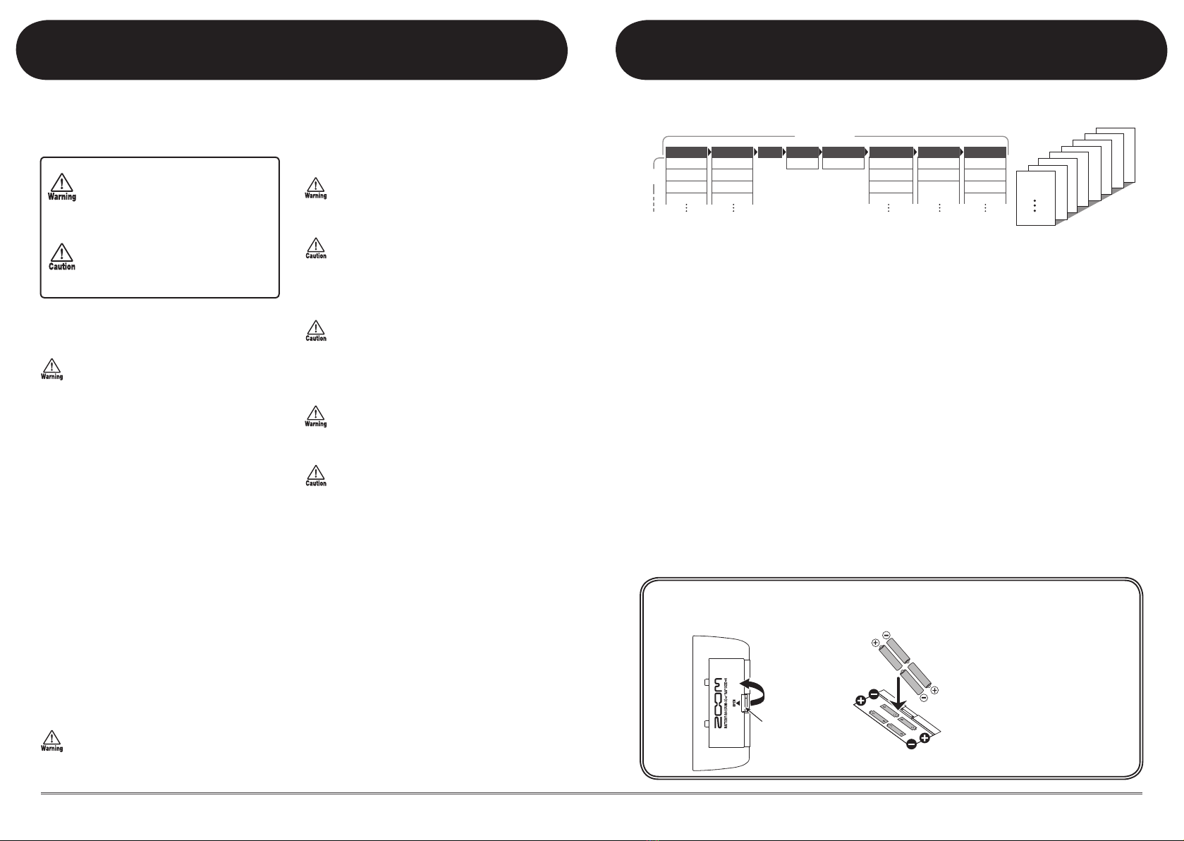
3. Close the cover of the
battery compartment.
Latch
1. Turn the G1N/G1XN over and
open the cover of the battery
compartment on the bottom.
Press latch to release
and then lift cover.
Operating the G1N/G1XN on batteries
Four IEC R6
(size AA) batteries
2. Insert four fresh IEC
R6 (size AA) batteries.
Compressor
Auto Wah
Booster
Tremolo
FD COMBO
VX COMBO
US BLUES
BG CRUNCH
Hall
Room
Spring
Arena
Delay
Tape Echo
Analog
Delay
Amp Sim.ZNR Chorus
Ensemble
Flanger
Step
COMP/EFX DRIVE EQ
MODULATION
REVERBDELAYAMPZNR
Effect modules
Effect
types
BANK 3
PATCH 0
PATCH 1
PATCH 9
BANK 2
PATCH 0
PATCH 1
PATCH 9
BANK 1
PATCH 0
PATCH 1
PATCH9
BANK 0
PATCH 0
PATCH 1
PATCH 9
BANK d
PATCH 0
PATCH 1
PATCH 9
BANK C
PATCH 0
PATCH 1
PATCH 9
BANK b
PATCH 0
PATCH 1
PATCH9
BANK A
PATCH 0
PATCH 1
PATCH 9

4ZOOM G1N/G1XN
5
ZOOM G1N/G1XN
Controls and Functions / Connections (G1N)
[VALUE] knob
[BANK UP·TAP] key
RHYTHM [R/P] key
Module selector
[W]/[Q] foot switches
[INPUT] jack
[CONTROL IN] jack
AC adapter
Guitar
Guitar amplifier
Headphones
FP01/FP02
FS01
Serves for connecting the guitar.
When operating the G1N on
batteries, inserting the guitar
cable plug into this jack will
turn the unit on.
Serves for connection of the optional foot switch (FS01)
or expression pedal (FP01/FP02).
[DC IN] jack
An AC adapter (ZOOM AD-0006) with a rated
output of 9 volts DC, 300 mA (center minus plug)
can be plugged into this jack.
In play mode, the key switches to the next higher bank. In other
modes, the key serves for manual adjustment of rhythm pattern
tempo as well as parameters related to timing and cycle.
[STORE] key
Display
Serves for storing edited patches in memory and for copying
patches to another location.
Shows bank and patch numbers, setting values,
and other information for operating the G1N.
This knob serves for changing parameter values and setting the
level of the overall patch.
These switches are used for selecting patches, controlling the tuner,
and other functions.
Serves to start and stop the rhythm pattern in
play mode and rhythm mode.
Switches between play mode, rhythm mode,
and edit mode. In edit mode, the knob selects
the module/parameter for operation.
Top Panel
Rear Panel
When operating the G1N on batteries, it is
advisable to disconnect the guitar cable
plug from the [INPUT] jack when not using
the unit, to conserve battery power.
[OUTPUT/PHONES] jack
This stereo phone jack serves for connection to
the guitar amplifier. It is also possible to use a Y
cable for sending the output to two amplifiers, or
to plug a pair of stereo headphones into this jack.
Controls and Functions / Connections (G1N)

6ZOOM G1N/G1XN
7
ZOOM G1N/G1XN
Controls and Functions / Connections (G1XN)
[VALUE] knob
[BANK UP·TAP] key
RHYTHM [R/P] key
Module selector
[W]/[Q] foot switches
[INPUT] jack AC adapter
Guitar
Guitar amplifier
Headphones
Serves for connecting the guitar. When
operating the G1XN on batteries,
inserting the guitar cable plug into this
jack will turn the unit on.
[DC IN] jack
An AC adapter (ZOOM AD-0006) with a rated output
of 9 volts DC, 300 mA (center minus plug) can be
plugged into this jack.
In play mode, the key switches to the next higher bank. In other
modes, the key serves for manual adjustment of rhythm pattern
tempo as well as parameters related to timing and cycle.
Expression pedal
Display
Can be used as a volume pedal or as a real-time controller for
adjusting effect parameters. (For details, see page 20.)
[PEDAL ASSIGN] key
Selects the module to be controlled by the built-in expression pedal.
[STORE] key
Serves for storing edited patches in memory and for copying
patches to another location.
Shows bank and patch
numbers, setting values, and
other information for
operating the G1XN.
This knob serves for changing parameter values and setting the
level of the overall patch.
These switches are used for selecting patches, controlling the tuner,
and other functions.
Serves to start and stop the
rhythm pattern in play mode
and rhythm mode.
Switches between play mode,
rhythm mode, and edit mode.
In edit mode, the knob selects
the module/parameter for
operation.
Top Panel
Rear Panel
When operating the G1XN on
batteries, it is advisable to
disconnect the guitar cable plug
from the [INPUT] jack when not
using the unit, to conserve battery
power.
[OUTPUT/PHONES] jack
This stereo phone jack serves for connection to the guitar
amplifier. It is also possible to use a Y cable for sending the
output to two amplifiers, or to plug a pair of stereo
headphones into this jack.
Controls and Functions / Connections (G1XN)

8ZOOM G1N/G1XN
9
ZOOM G1N/G1XN
Selecting a Patch for Playing (Play Mode)
Bank
name
Patch
number
MN
MN
The volume control on the connected amplifier
should be turned down.
When using the unit on batteries
Plugashieldedcableintothe[INPUT]jack.
When using the unit with an AC adapter
Plugthecablefromtheadapterintothe[DCIN]
jack.
Turntheguitaramplifieronandadjustthevolumeto
a suitable position.
Set the Module selector to "PLAY".
The bank and patch number are shown on the display.
Immediately after turning the G1N/G1XN on, the unit
will be in play mode, regardless of the position of the
Module selector.
Turn power on
1
Set the G1N/G1XN to play mode
2
Directly switch a bank
4
Adjust the master level
5
Press the [BANK UP·TAP] key.
Repeatedlypressingthekeycyclesthroughbanksin
the order A ... d, 0 ... 3, A.
With the G1N, using the foot switch (FS01) to switch
banks is also possible (gp. 18).
Operate the [VALUE] knob.
The master level setting appears on the display.
The master level setting applies to all patches. The
settingrangeis0–98,1.0.Itwillberesetto80when
power is turned off and then on again.
When using headphones, this knob adjusts the listening
volume.
Select a patch
3
Use the foot switches.
Press the [Q]footswitchtocallupthenexthigher
patch.
Press the [W]footswitchtocallupthenextlower
patch.
Repeatedlypressingonefootswitchcyclesthrough
patchesintheorderA0–A9...d0–d9,00–09...
30–39,A0.
This section explains basic functions of the play mode.
HINT
HINT
HINT
80
A0 B0
A0 A1
A0 39

10 ZOOM G1N/G1XN
11
ZOOM G1N/G1XN
Using the Tuner
Using the Tuner
•SettingtheG1N/G1XNtothebypass
condition
In play mode or rhythm mode (gp. 12), press both
[W]/[Q]footswitchestogether.Whenthe
indication "bP" appears on the display, release the
switches within 1 second.
•SettingtheG1N/G1XNtothemutestate
In play mode or rhythm mode (gp. 12), press both
[W]/[Q]footswitchestogether.Waituntilthe
indication "bP" on the display changes to "Mt" and
then release the foot switches.
The bypass or mute condition cannot be activated when
the unit is in edit mode (gp. 14).
Switch to bypass or mute
1
To use the tuner function of the G1N/G1XN, the built-in effects must be bypassed (temporarily
turned off) or muted (original sound and effect sound turned off). Play the open string to tune, and adjust the pitch.
To fine-adjust the reference pitch of the G1N/G1XN
tuner, turn the [VALUE] knob in the bypass/mute
condition.
When you turn the knob, the current reference pitch
is shown for a time on the display. The default setting
is40(centerA=440Hz).
While the reference pitch is shown, turn the
[VALUE]knobtoadjustthevalueintherangefrom
35–45(centerA=435to445Hz).
When power is turned off and on again, the reference
pitch setting will be reset to 40 (center A = 440 Hz).
Press one of the [W]/[Q] foot switches.
Tune your instrument
2
Adjusting the reference pitch of the tuner
3
Return to play mode
4
BP
BP MT
B P
M T
NOTE
NOTE
A 8
Pitch is high Pitch is correct Pitch is low
Indication turns faster the more the pitch is off
The left side of the display shows the note
which is closest to the current pitch.
The right side of the display shows a symbol that
indicates by how much the tuning is off.
40
40
42
40
40
42
Patchchangeatbypass/mute
When you press both [W]/[Q] foot switches
together while playing your instrument, the
sound may change momentarily just before
the bypass/mute condition is activated.
This is because the G1N/G1XN switches to
the next higher or lower patch when one of
the foot switches is pressed slightly earlier.
(When you cancel the bypass/mute
condition, the original patch number will be
active again.)
This behavior is not a defect. It is due to the
very high speed at which the G1N/G1XN
responds to patch switching. To prevent the
sound change caused by the above
condition, do not produce sound with your
instrument until the bypass/mute condition
is fully established.

12 ZOOM G1N/G1XN
13
ZOOM G1N/G1XN
Using the Rhythm Function (Rhythm Mode)
Set the Module selector to the "RHYTHM" position.
The number of the currently selected rhythm pattern
(01 – 40) appears on the display.
Also while in rhythm mode, you can use the patch that
was selected immediately before switching the mode.
However, reverb effects are disabled in rhythm mode.
The rhythm function can also be used in play mode.
Press the RHYTHM [R/P] key.
Rhythm pattern playback will start also if you press the
RHYTHM [ R/ P] key in play mode. However,
changing the rhythm pattern or adjusting the rhythm
volume and tempo is not possible.
To switch between the 40 built-in rhythm patterns,
press one of the [W]/[Q]footswitches.
(For information on pattern contents, see page 26.)
When you press both [W]/[Q] foot switches in rhythm
mode, the G1N/G1XN switches to the bypass/mute
condition. The tuning function (gp. 10) can be used in
this condition while playing the rhythm pattern.
Select rhythm mode
1
Start the rhythm function
2
Select a rhythm pattern
3
This section describes how to use the built-in rhythm function that plays realistic drum sounds in
various patterns. Turn the [VALUE] knob.
The current setting (0 – 30) is shown briefly on the
display.
Press the RHYTHM [R/P] key.
The G1N/G1XN returns to the previous condition.
Therhythmpatterntempocanbeadjustedinthe
rangeof40–250BPM(beatsperminute).
•Tocontinuouslychangethetempo
Hitthe[BANKUP·TAP]keyonceandthenturn
the[VALUE]knobwhilethetempovalueisbeing
shown on the display.
•Tomanuallyspecifythetempo
Hitthe[BANKUP·TAP]keyatleasttwiceinthe
desired interval. The G1N/G1XN automatically
detects the interval in which the key is pressed the
second and subsequent times, and sets the tempo
accordingly (tap tempo function).
While the above steps are carried out, the new tempo
value (40 – 250) is shown briefly on the display. For
valuesintherangefrom100to199,adotisshownin
the center, and for values of 200 and above, dots are
shown in the center and in the bottom right corner.
With the G1N, using a separately available foot switch
to manually adjust the tempo is also possible (gp. 18).
The G1XN does not support use of a foot switch.
Adjust the rhythm volume
4
Stop the rhythm
6
Adjust the tempo
5
HINT
HINT
HINT
01
Rhythm pattern
number
25
40
Push once
HINT
20
40
Dot is shown
Tempo = 120 BPM
Dots are shown
Tempo = 240 BPM
Detected automatically

14 ZOOM G1N/G1XN
15
ZOOM G1N/G1XN
Editing a Patch (Edit Mode)
Turn the Module selector to select the effect module
and parameter to edit. The available settings are
listed below.
(1) PATCH LEVEL (Prm)
(2) COMP/EFX module (Type&Prm)
(3) DRIVE module (Type)
(4) DRIVE module (Prm)
(5) – (7) EQ module (Prm)
(8) ZNR/AMP module (Type&Prm)
(9) MODULATION module (Type&Prm1)
(10) MODULATION module (Prm2)
(11) DELAY module (Type&Prm1)
(12) DELAY module (Prm2)
(13) REVERB module (Type&Prm1)
(14) REVERB module (Prm2)
The "Type" and "Prm" indication in brackets
indicates the item category.
• Type&PrmorType&Prm1(Type&Parameter)
Item where the effect type (left side of display) and
parameter setting value (right side of display) are
adjustedsimultaneously.
•Type
Item where the effect type only is selected.
• PrmorPrm2(Parameter)
Item where the parameter setting value only is
adjusted.
Select the effect module/parameter
1
The patches of the G1N/G1XN can be freely edited by changing the effect type used by the
various modules and by changing the parameter settings. Try editing the currently selected patch to
create your own sound.
Turn the [VALUE] knob.
The setting of the selected item changes, and a dot (.)
appears in the bottom right of the display. This
indicates that a setting has been changed from the
currently stored value.
When you have selected a parameter that can be set
with the tap function (gp. 21), you can repeatedly hit
the [BANK UP·TAP] key at the desired interval to
specify the timing.
Press one of the [W]/[Q] foot switches.
The indication "oF" appears on the display and the
module is turned off. Pressing one of the switches
once more returns the setting to the previous
condition.
Set the Module selector to the "PLAY" position to
return to the play mode.
When you return to play mode and have made any
changes to the patch, the dot (.) will be shown in the
bottom right of the display. If you select another patch
in this condition, the changes you have made in edit
mode will be lost unless you store the patch first. To
retain the changes, store the patch as described on page
16.
Change the setting
2
To switch an effect module on and off
3
Terminate the edit mode
4
(1)
(2)
(3)(4)
(5)
(9)
(
10
)
(
11
)
(
12
)
(
13
)
(
14
)
(6) (7) (8)
C2
Dot indicates that setting
has been changed
HINT
NOTE
OF
C1
FD
25
Parameter
setting value
Parameter setting value
Effect type
Effect type
C1
FD
25
Parameter
setting value
Parameter setting value
Effect type
Effect type
C1
FD
25
Parameter
setting value
Parameter setting value
Effect type
Effect type
The EQ module has three
parameters, and the
MODULATION, DELAY, and
REVERB modules have two
parameters each.
Switching the type gives
access to the second and
third parameter.

16 ZOOM G1N/G1XN
17
ZOOM G1N/G1XN
Storing/Copying Patches (Store Mode)
The bank and patch number flash on the display.
Patches of preset banks (0 – 3) are read-only. No
patches can be stored or copied into these locations. If
you press the [STORE] key while a patch from these
banks is selected, the patch "A0" (bank A, patch number
0) will be selected automatically as default store/copy
target.
• Usethe[W]/[Q] foot switches to select the bank/
patch number.
• Toswitchonlythebank,usethe[BANKUP·
TAP] key.
· Only a user bank (A – d) can be selected as store/copy
target bank.
· During the store/copy process, the foot switch (FS01)
cannot be used to change banks.
In play mode or edit mode, press the [STORE] key
1
Select the store/copy target bank and patch number
2
An edited patch can be stored in a user bank (A – d). It is also possible to store an existing patch in
another location to create a copy. When the store/copy process is completed, the G1N/
G1XN returns to the previous mode, with the target
patch selected.
To cancel the store process, operate the [VALUE] knob
before pressing the [STORE] key again.
Press the [STORE] key once more
3
A0
NOTE
NOTE
A8
B8
B8
HINT
Even after overwriting user patches with
other patches, their original content can be
restored in a single operation ("All Initialize"
function).
To do this, turn power to the G1N/G1XN on
while holding down the [STORE] key.
The indication "AL" appears on the display.
To carry out the All Initialize function, press
the [STORE] key once more. All patch
settings are returned to the factory default
condition, and the unit switches to play
mode.
To cancel All Initialize, press the RHYTHM
[R/P] key instead of the [STORE] key.
When you carry out All Initialize, any
newly created patches that were
stored in the user-editable bank will
be deleted (overwritten). Perform
this operation with care to prevent
losing any patches that you want to
keep.
Restoring Factory Defaults
AL
NOTE

18 ZOOM G1N/G1XN
19
ZOOM G1N/G1XN
Using an External Foot Switch or Pedal (G1N only)
•Rhythmmode
When you press the foot switch two times or
more, the G1N detects the interval and
automaticallyadjuststhetempoaccordingly
(tap tempo function).
• Editmode/Storemode
The foot switch has no effect.
Using an expression pedal
When the optional expression pedal (FP01/
FP02)isconnectedtothe[CONTROLIN]
jack of the G1N, you can change effect
parameters in real time or use the pedal as a
vo lume co ntrol ler. The fun ction o f the
expression pedal can be saved individually for
each patch.
1.PlugtheFP01orFP02intothe
[CONTROLIN]jackoftheG1N.
2.Inplaymode,selectapatchfor
which you want to use the expression
pedal.
3.Set the Module selector to a position
other than "PLAY" or "RHYTHM".
The G1N/G1XN goes into edit mode.
4.Hold down the RHYTHM [R/P] key
and turn the [VALUE] knob to select
one of the following modules for
control by the expression pedal.
Display Control target
OF Off
VP Volume
WP COMP/EFXmodule
GP DRIVEmodule
MP MODULATIONmodule
DP DELAYmodule
RP REVERBmodule
· In th e s ect i o n "E f f ec t Ty p es an d
Parameters" (gp. 21), effect types/
parameters that can be controlled with
the expression pedal are indicated by a
pedal symbol.
· If a module is selected for which no
pedal symbol is shown, the expression
pedal will have no effect for that patch.
5.Save the patch.
The expression pedal setting is stored with
the patch.
6.In play mode, select the patch and
operate the expression pedal.
The respective parameter changes.
In bypass mode, the expression pedal
always functions as a volume pedal,
regardless of the setting.
The expression pedal operates also in edit
mode.
Changing the Way Patches Are Called Up
This section describes how to change the patch selection method of the G1N/G1XN to "pre-
select". In this mode, you first select the patch to use next, and then perform an additional step to
activate the patch.
1.TurnpowertotheG1N/G1XNon
while holding down the [Q] foot
switch.
The indication "PrE-SElEct" scrolls on the
display.
2.Inplaymode,selectthepatchtouse
next.
The selected new bank and patch number
flash on the display. The sound does not
change yet.
3.When you have specified the patch to
use, press both [W]/[Q] foot switches
together.
The patch change is accepted, causing the
sound to change, and the display changes
from flashing to permanently lit.
4.
ToreturntheG1N/G1XNtothenormal
patch selection method, simply turn
power off and then on again.
The patch selection method is automatically
reset to conventional operation.
Using an External Foot Switch or Pedal (G1N only)
The[CONTROLIN]jackontheG1Nallowsconnectionofanoptionalfootswitchorexpression
pedal to control effects and the rhythm function. This section explains how to use this capability.
Using a foot switch
Simply connect the optional foot switch (FS01)
to the [CONTROL IN] jack of the G1N and
turn the unit on. This allows you to switch
banks and specify the tempo for rhythm
patterns with the foot switch.
Depending on the currently selected mode, the
foot switch operates as follows.
•Playmode
Pressing the foot switch selects the next
higher bank.
B0 B0
B 0
HINT
HINT
B0 B0

20 ZOOM G1N/G1XN
21
ZOOM G1N/G1XN
Effect Types and Parameters
• Moduleselector
Shows the position of the knob at which
this module/parameter is called up.
• Expressionpedal
Indicates a par ame ter t hat can be
controlled with the expression pedal.
• Tap
Indicates a parameter that can be set by
repeatedlytappingthe[BANKUP·TAP]
key. When the module/effect type is
selected in edit mode, the parameter
(modulation rate or delay time, etc.) will be
set according to the interval in which the
key is pressed.
Using the built-in expression pedal (G1XN only)
TheG1XNletsyouadjustthevolumeor
parameters in real time using the expression
pedal on the unit. This section explains how to
use this capability.
[PEDAL ASSIGN] key operation
ThetoppaneloftheG1XNhasa[PEDAL
ASSIGN]key.Themoduletobecontrolledby
the pedal can be selected with this key.
1.Inplaymodeoreditmode,pressthe
[PEDALASSIGN]keytoselectthe
control target module.
The module currently selected as control
targetisindicatedbytherowofLEDsabove
the[PEDALASSIGN]key.
All out Pedal is inactive
Volume
COMP/EFX module
DRIVE module
MODULATION module
DELAY module
REVERB module
Besides the method described above, you
can also select the module to control by
holding down the [RHYTHM] key and
turning the [VALUE] knob. This is the
same as for the G1N. (For details, see
page 19.)
2.Storethepatchasrequired.
3.In play mode, select the patch and
operate the expression pedal.
The respective parameter changes in real
time.
4.To toggle the module assigned to the
pedal between on and off, briefly
push the pedal fully down.
Whenthemodule isoff,therespectiveLED
abovethe[PEDALASSIGN]keyflashes.This
function can also be used in edit mode.
Adjusting the expression pedal
The responsiveness of the expression pedal on
the G1XN can be readjusted as necessary. If
the effect change seems insufficient when
pushing the pedal down, or if the volume or
tone changes excessively even when the pedal
isonlylightlypushed,adjustthepedalas
follows.
1.Holddownthe[PEDALASSIGN]key
whileturningpowertotheG1XNon.
The indication "dn" appears on the display.
2.Fullyraisetheexpressionpedaland
press the [STORE] key.
Theindication"UP"appearsonthedisplay.
3.Push the expression pedal fully down
and release it.
Push strongly, so
that pedal touches
here
When foot is lifted,
pedal returns slightly
4.Press the [STORE] key once more.
Theadjustmentiscomplete,andtheunit
returns to the play mode. If the indication
"Er"isshown,repeattheprocedurefrom
step 2.
Effect Types and Parameters
Explanation of symbols
HINT
* Manufacturer names and product names mentioned in this listing are trademarks or
registered trademarks of their respective owners. The names are used only to illustrate
sonic characteristics after which the effects are modeled and do not indicate any affiliation
with ZOOM CORPORATION.
For some effect modules, you can select an effect type from several possible choices.
n PATCH LEVEL
PATCH LEVEL (Prm)
Sets the overall volume level of the patch.
2 1 0
Thesettingrangeis2–98,and1.0.Asettingof80correspondstounitygain(inputlevelandoutputlevel
are equal).
n COMP/EFX (Compressor/Special Effects) module
COMP/EFX (Type&Prm)
Selects the COMP/EFX module effect type and parameter.
C 1 C 9
Compressor
ThisisanMXRDynacomptypecompressorwhichlimitshigh-levelsignalsandboostslow-levelsignalsto
compresstheoveralldynamicsofthesignal.Highersettingsresultinhighersensitivity.
A 1 A 9
Auto Wah
Thiseffectvarieswahinaccordancewithpickingintensity.Highersettingsresultinhighersensitivity.
B 1 B 9
Booster
Raisessignalgainandcreatesadynamicsound.Highersettingsresultinhighergain.
T 1 T 9
Tremolo
Thiseffectperiodicallyvariesthevolume.Highersettingsresultinfastermodulationrate.
P 1 P 9
Phaser
Thiseffectproducessoundwithapulsatingcharacter.Highersettingvaluesresultinfastermodulationrate.
R 1 R 9
RingMod(RingModulator)
Thiseffectproducesametallicringingsound.Highersettingsresultinhighermodulationfrequency.

22 ZOOM G1N/G1XN
Effect Types and Parameters
23
ZOOM G1N/G1XN
Effect Types and Parameters
L D
LEAD
E D
EXTREMEDS
Smooth, bright distortion sound. Highgainsoundwiththemostpowerfulgain
of any distortion effect in the world.
A
ACO.SIM(AcousticSimulator)
This effect makes an electric guitar sound
like an acoustic guitar.
GAIN (Prm)
Sets the DRIVE module parameters. The parameter action differs, depending on
whether a distortion effect type (Fd – Ed) or Aco.Sim (Ac) is selected.
When distortion effect type (Fd – Ed) is selected
0 3 0
GAIN
Adjuststhegain(distortionintensity).
When Ac is selected
0 1 0
TOP
Adjuststhecharacteristicstringtoneofacousticguitar.
* Manufacturer names and product names mentioned in this listing are trademarks or registered trademarks of their
respective owners. The names are used only to illustrate sonic characteristics after which the effects are modeled and do
not indicate any affiliation with ZOOM CORPORATION.
n EQ module (equalizer)
EQ LO (Prm) EQ MID (Prm) EQ HI (Prm)
Adjusts the LO
band of the EQ
module.
Adjusts the MID
band of the EQ
module.
Adjusts the HI
band of the EQ
module.
8 1 8
Lo
8 1 8
Mid
8 1 8
Hi
Adjuststhelowrange
(160Hz)boost/cut.
Adjuststhemidrange
(800Hz)boost/cut.
Adjuststhehighrange
(3.2kHz)boost/cut.
n ZNR/AMP (ZNR/Amp Simulator) module
ZNR/AMP (Type&Prm)
This module combines ZOOM's proprietary ZNR (removes noise during play pauses
without affecting sound quality) with an amp simulator (recreates the sound of various
speaker cabinets). Type and parameters are adjusted at the same time.
0 9
ZNR(ZOOMNoiseReduction)
Thisisthenoisereductionfunctiononly.Highersettingsresultinastrongereffect.Setthevalueashighas
possible without causing the sound to be cut off unnaturally.
C 0 C 9
Combo&ZNR
CombinationofZNRwithampsimulatorthatrecreatesthesoundofacomboampwithclosed-backcabinet.
Theright-digitvaluecontrolsZNRsensitivity.
B 0 B 9
BrightCombo&ZNR
CombinationofZNRwithampsimulatorthatrecreatesthesoundofabrightcomboampwithopen-back
cabinet.Theright-digitvaluecontrolsZNRsensitivity.
S 0 S 9
Stack&ZNR
CombinationofZNRwithampsimulatorthatrecreatesthesoundofastackampcabinet.Theright-digit
valuecontrolsZNRsensitivity.
S 1 S 9
Slow Attack
Thiseffectreducestheattackrateofeachindividualnote.Highersettingsresultinslowerattacktimes.
V 1 V 9
Pedal Vox
ThiseffectsimulatesavintageVoxwahpedalathalf-open.Highersettingsshifttheemphasizedfrequency
upwards.
1 9
Pedal Cry
ThiseffectsimulatesavintageJenCrybabypedalathalf-open.Highersettingsshifttheemphasized
frequency upwards.
n DRIVE module (distortion effects)
DRIVE (Type)
Selects the effect type for the DRIVE module.
F D
FDCOMBO
V
VXCOMBO
SoundofaFenderTwinReverb('65model)
favored by guitarists of many music styles.
Sound modeled on the Class A drive combo
amp Vox AC30.
B L
USBLUES
B G
BGCRUNCH
CrunchsoundofaFenderTweedBassman. CrunchsoundoftheMesaBoogieMkIII
combo amp.
H W
HW STACK
M C
MS CRUNCH
Soundofthelegendaryall-tubeHiwatt
Custom100fromBritain.
CrunchsoundoftheMarshall1959thathas
become legendary.
M D
MS DRIVE
P V
PV DRIVE
HighgainsoundoftheMarshallstackamp
JCM2000.
HighgainsoundofaPeavey5150developed
in cooperation with a world-famous hard
rock guitarist.
D D
DZ DRIVE
B D
BGDRIVE
Highgainsoundbasedonthechannel3ofthe
hand-madeGermanguitarampDiezelHerbert
with three separately controllable channels.
HighgainsoundoftheMesaBoogieDual
Rectifierredchannel(vintagemode).
O D
OVER DRIVE
G U
GOVERNOR
SoundoftheBossOD-1thatfirstcreatedthe
"overdrive" concept.
SoundoftheGuv'nordistortioneffectfrom
Marshall.
S Q
SQUEAK
F S
FUZZ SMILE
SimulationoftheProCoRatfamousforits
edgy distortion sound.
Sound of the Fuzz Face that made rock
history with its zany look and smashing
sound.
H B
HOTBOX
C
Z CLEAN
Simulation of the compact Matchless
HotBoxpreampwithbuilt-intubes. Zoom original flat clean sound.
M
ZMP1
N
Z NEOS
Original sound that combines characteristics
of the ADA MP1 and Marshall JCM800.
Crunch sound modeled on a modified Vox
AC30.

24 ZOOM G1N/G1XN
Effect Types and Parameters
25
ZOOM G1N/G1XN
Effect Types and Parameters
n MODULATION module
MODULATION (Type&Prm1) RATE (Prm2)
Selects the MODULATION module
effect type and controls parameter
1 at the same time.
Controls the value of parameter 2
of the MODULATION module. The
parameter action differs, depending
on the effect type.
C 1 C 9
Chorus
1 5 0
Rate
This effect mixes a variable pitch-shifted
componenttotheoriginalsignal.Higher
right-digit settings result in higher effect
sound mixing ratio.
Adjuststhemodulationrate.
E 1 E 9
Ensemble
This is a chorus ensemble with three-
dimensionalmovement.Higherright-digit
settings result in higher effect sound mixing
ratio.
F 1 F 9
Flanger
1 5 0
Rate
This effect produces a resonating and
stronglyundulatingsound.Higherright-digit
settings emphasize the characteristics of the
effect.
Adjuststhemodulationrate.
S 1 S 9
Step
Special effect that changes the sound in a
staircasepattern.Higherright-digitsettings
emphasize the characteristics of the effect.
P 1 P 9
Pitch Shift
1 1 2
D T
2 4
2 1
Shift
This effect shifts the pitch of the original
soundupordown.Higherright-digitsettings
increase the mixing ratio of the effect sound.
Sets the pitch shift amount in semitones. "dt"
results in a detune effect.
M 1 M 9
Mono Pitch
This is a monophonic pitch shifter (for
single-note playing) with reduced flutter.
Higherright-digitsettingsincreasethe
mixing ratio of the effect sound.
H 1 H 9
HPS
(HarmonizedPitchShifter)
C C O
,
D D O
F
,
,
E
F O G
,
A O B
,
G O A
,
Key
This is an intelligent pitch shifter that
automaticallygeneratesmajorscale
harmoniesaccordingtoapresetkey.Higher
right-digit settings increase the mixing ratio
of the effect sound.
Specifies the tonic for the scale used for
pitch shifting. The "o" symbol stands for #.
V 1 V 9
Vibrato
1 5 0
Rate
This is an effect with automatic vibrato.
Higherright-digitsettingsemphasizethe
vibrato intensity.
Adjuststhemodulationrate.
B 1 B 9
PitchBend
0 1 0
Pedal Position
This effect allows using the expression pedal
tochangethepitchinrealtime.Right-digit
settings select the pitch change type caused
by the expression pedal (see Table 1).
Sets the initial value for the pitch shift
amount (the value that is active when the
pedal is at rest). The original sound/effect
sound level balance also changes according
to the parameter 1 setting.
b1
b2
b3
b4
b5
0 cent
0 cent
0 cent
0 cent
0 cent
+1 octave
+2 octaves
-100 cent
-2 octaves
-
Pedal fully depressed
(maximum)
Pedal fully raised
(minimum)
Type&Prm1
[Table 1]
Prm2=0 Prm2=1.0
Pedal fully depressed
(maximum)
Pedal fully raised
(minimum)
Type&Prm1
Prm2=0 Prm2=1.0
b6
b7
b8
b9
-1 octave + original sound
-700 cent + original sound
Doubling
-(0Hz) + original sound
+1 octave + original sound
+500 cent + original sound
Detune + original sound
+1 octave + original sound
D 1 D 9
Delay
1 2 0
Time(DelayTime)
This is a delay with a maximum setting of
2000msec.Higherright-digitsettings
increase the mixing ratio of the effect sound
and the feedback amount.
Sets the delay time. In the 10 – 1000
millisecondrange,theadjustmentis
performedin10-msecsteps(1–99,1.0).
Above1second,theadjustmentisperformed
in 100-msec steps (1.1 – 2.0).
n DELAY module
DELAY (Type&Prm1)
Selects the DELAY module effect type and controls parameter 1 at the same time.
D 1 D 9
Delay
This is a delay with a maximum setting of 5000 msec. The right-digit setting values control the mixing ratio
of the effect sound and the feedback amount.
T 1 T 9
Tape Echo
This effect simulates a tape echo with a long delay time of up to 5000 msec. The right-digit setting values
control the mixing ratio of the effect sound and the feedback amount.
A 1 A 9
Analog Delay
This effect simulates an analog delay with a long delay time of up to 5000 msec. The right-digit setting
values control the mixing ratio of the effect sound and the feedback amount.
P 1 P 9
Ping Pong Delay
This is a ping-pong type delay where the delay sound alternates between left and right. The right-digit setting
values control the mixing ratio of the effect sound and the feedback amount.
TIME (Prm2)
Controls parameter 2 of the DELAY module.
1 5 0
Time(DelayTime)
Setsthedelaytime.Inthe10–1000millisecondrange,theadjustmentisperformedin10-msecsteps
(1–99,1.0).Above1second,theadjustmentisperformedin100-msecsteps(1.1–5.0).

26 ZOOM G1N/G1XN
Effect Types and Parameters
27
ZOOM G1N/G1XN
Specications
n REVERB module
REVERB (Type&Prm1)
Selects the REVERB module effect type and controls parameter 1 at the same time.
H 1 H 9
Hall
Thisreverbeffectsimulatestheacousticsofaconcerthall.Higherright-digitsettingsincreasethemixing
ratio of the effect sound.
R 1 R 9
Room
Thisreverbeffectsimulatestheacousticsofaroom.Higherright-digitsettingsincreasethemixingratioof
the effect sound.
S 1 S 9
Spring
Thiseffectsimulatesaspring-typereverb.Higherright-digitsettingsincreasethemixingratiooftheeffect
sound.
A 1 A 9
Arena
Thisreverbeffectsimulatestheacousticsofalargevenuesuchasasportsarena.Higherright-digitsettings
increase the mixing ratio of the effect sound.
T 1 T 9
Tiled Room
Thisreverbeffectsimulatestheacousticsofatiledroom.Higherright-digitsettingsincreasethemixingratio
of the effect sound.
DECAY (Prm2)
Controls parameter 2 of the REVERB module. This parameter is common to all effect
types.
1 3 0
Decay
Adjuststhedecayduration.
Rhythm Function Preset Patterns
# Name TimSig # Name TimSig # Name TimSig # Name TimSig
18beat 1 4/4 11 METAL 2 4/4 21 POP 3 4/4 31 BALLAD 1 4/4
28beat 2 4/4 12 THRASH 4/4 22 DANCE 1 4/4 32 BALLAD 2 3/4
38beat 3 4/4 13 PUNK 4/4 23 DANCE 2 4/4 33 BLUES 1 4/4
48shuffle 4/4 14 DnB 4/4 24 DANCE 3 4/4 34 BLUES 2 3/4
516beat 1 4/4 15 FUNK 1 4/4 25 DANCE 4 4/4 35 JAZZ 1 4/4
616beat 2 4/4 16 FUNK 2 4/4 26 3per4 3/4 36 JAZZ 2 3/4
716shuffle 4/4 17 HIPHOP 4/4 27 6per8 3/4 37 METRO 3 3/4
8ROCK 4/4 18 R'nR 4/4 28 5per4 1 5/4 38 METRO 4 4/4
9HARD 4/4 19 POP 1 4/4 29 5per4 2 5/4 39 METRO 5 5/4
10 METAL 1 4/4 20 POP 2 4/4 30 LATIN 4/4 40 METRO
Troubleshooting
Specifications
• Nopower
Referto"Turnpoweron"onpage8.
• Reverbeffectdoesnotoperate
While a rhythm pattern is playing, the reverb
effect is not available. Stop the rhythm pattern
first (gp. 12).
• Patchswitchingdoesnotchangethe
sound
Is the patch selection method of the G1N/G1XN
set to "pre-select" (gp. 18)? Turn power off and
then on again to return to normal operation.
• Highlevelofnoise
IsZOOMACadapterbeingused?Besuretouse
onlyanadapterfor9VDC,300mAwithcenter
minus plug (ZOOM AD-0006).
• Batterylifeisshort
Are manganese batteries being used? Continuous
operation time is about 12 hours with alkaline
batteries.
Effect types 54
Effect modules max. 8 simultaneous modules
Patch memory Userarea: 10patchesx4banks=40
Preset area: 10 patches x 4 banks = 40
Total 80 patches
Sampling frequency 96kHz
A/Dconverter 24 bit, 128 times oversampling
D/Aconverter 24 bit, 128 times oversampling
Signal processing 32 bit
Frequency response 20Hz-40kHz+1.0dB-4.0dB(10-kilohmload)
Display 2-digit7-segmentLED
Input Standardmonophonejack
Rated input level -20dBm
Input impedance 470 kilohms
Output Standardstereophonejack(doublesasline/headphonejack)
Maximum output level Line+3dBm
(output load impedance of 10 kilohms or more)
Phones20mW+20mW(into32-ohmload)
Control input For FP02/FP01 or FS01 (G1 only)
Power requirements
AC adapter 9VDC,300mA(centerminusplug)(ZOOMAD-0006)
Batteries G1N/G1XN FourIECR6(sizeAA)batteries,approx.
12 hours continuous operation (alkaline batteries)
Dimensions G1N 155mm(D)x136mm(W)x52mm(H)
G1XN 155mm(D)x234mm(W)x52mm(H)
Weight G1N 350 g (without batteries)
G1XN 600 g (without batteries)
Options ExpressionpedalFP01/FP02orFootswitchFS01(G1Nonly)

ZOOM CORPORATION
4-4-3, Kandasurugadai, Chiyoda-ku, Tokyo 101-0062, Japan
Web Site: http://www.zoom.co.jp
G1N/G1XN - 5000-1
TheFCCregulationwarning(forU.S.A.)
ThisequipmenthasbeentestedandfoundtocomplywiththelimitsforaClassBdigitaldevice,pursuanttoPart15of
theFCCRules.Theselimitsaredesignedtoprovidereasonableprotectionagainstharmfulinterferenceinaresidential
installation. This equipment generates, uses, and can radiate radio frequency energy and, if not installed and used in
accordance with the instructions, may cause harmful interference to radio communications. However, there isno
guarantee that interference will not occur in a particular installation. If this equipment does cause harmful interference
to radio or television reception, which can be determined by turning the equipment off and on, the user is encouraged
to try to correct the interference by one or more of the following measures:
• Reorientorrelocatethereceivingantenna.
• Increasetheseparationbetweentheequipmentandreceiver.
• Connecttheequipmentintoanoutletonacircuitdifferentfromthattowhichthereceiverisconnected.
• Consultthedealeroranexperiencedradio/TVtechnicianforhelp.
For EU Countries
Declaration of Conformity:
This product complies with the requirements of EMC Directive 2004/108/EG and Low
Voltage Directive 2006/95/EC

This manual suits for next models
3
Table of contents
Other Zoom Music Pedal manuals

Zoom
Zoom 508 User manual

Zoom
Zoom G3 User manual

Zoom
Zoom B2.1u User manual

Zoom
Zoom G1 X Four User manual

Zoom
Zoom 8080 User manual

Zoom
Zoom G1 Four User manual

Zoom
Zoom 509 Modulator User manual

Zoom
Zoom 506 BASS User manual

Zoom
Zoom Choir 5050 User manual

Zoom
Zoom Multistomp MS-70CDR Mounting instructions

Zoom
Zoom G2 User manual

Zoom
Zoom G1 X Four User manual

Zoom
Zoom Dual Power 510 Driver User manual

Zoom
Zoom Power Drive PD-01 User manual

Zoom
Zoom 9000 User manual

Zoom
Zoom 2020 User manual

Zoom
Zoom 506II Bass User manual

Zoom
Zoom MULTISTOMP MS-100BT General instructions

Zoom
Zoom G2.1u User manual

Zoom
Zoom G2.1u User manual