ZOSI W4 Pro User manual

W4 Pro Wireless
Security Camera System
Quick Start Guide
ZOSI Technology Co., Ltd.
3/F, Taitan Industrial Park,
Xiangzhou District, Zhuhai, Guangdong 519000, China
Thanks for your purchase at ZOSI.
This quick start guide will guide you through the initial installation
and related settings. In addition to following this guide, please visit
(https://zositech.com/) for more installation videos, tips and detailed
information.
If you have any problems about our products, please visit our online
support center (https://www.zositech.com/support-center/) or contact us
before returning.
V2.U.09.Z

Contents
EN 01
ES
14

01
What's in the Box
01
Quick Start Guide

02
Gallery & Specs
02
NOTE: NVR with hard drive support 24/7 recording.
2.1 Network Video Recorder
2.2 Camera
①VGA port: connect monitor with VGA port to NVR via VGA cable
②HDMI port: connect monitor with HDMI port to NVR via HDMI cable
③Backup USB port: insert USB drive for backup or system upgrade
④Ethernet port: connect router or switch to NVR via Ethernet cable
⑤Mouse USB port: connect to mouse
⑥Power port: connect to power supply
⑦Audio port: audio signal output
⑧Antenna: transmit wireless signal
①Lens: capture image and video
②Spotlights: illumination and light alarm
③IR-LEDs: provide night vision in dark
environment
④CDS: day and night auto switch
⑤Microphone: for voice intercom
⑥Speaker: for voice intercom and voice alarm
⑦Antenna: transmit wireless signal
⑧Warning light: It lights up when the camera is turned on. The warning light alarm can
be turned off on Siren-Light Alarm NVR interface.
①VGA port
②HDMI port ⑦Audio port
⑤Mouse USB port ⑥Power port
④Ethernet port
⑧Antenna
③Backup USB port
①Lens ⑦Antenna
⑤Microphone
④CDS
⑧Warning light
⑥Speaker
③IR-LEDs
②Spotlights*2

03
How to Connect the System
04
How the System Works
03
The wireless NVR system consists of two parts. One is the NVR connected to the monitor,
and the other is the IP cameras installed. Both NVR and IPC need independent power
supply to work. Users can watch the real-time video captured by each IPC on the monitor.
These images will also be saved in NVR for later playback at any time.
To ensure that the product can work normally, we recommend that you connect the whole
system before installation to see if there is any damage during transportation.
How to connect the system:
1. Connect NVR to router using a network cable.
2. Connect monitor to NVR via HDMI or VGA port(VGA cable is not included).
3. Connect the included USB mouse to the top USB port of NVR.
4. Connect NVR to power supply (12V power adapter)
5. After the system starts, connect camera to the system (maximum support 8
channels).
6. The monitor will display live video of the camera.

04
Camera Installation Steps
05
4. Adjust the angle
3. Install the camera
1. Mount the antenna 2. Insert wall plugs into
the holes
1. Adjust the camera antenna to keep it vertical to get the best reception.
2. Drill screw holes on the wall according to the mounting hole template, and insert the
rubber plugs into the holes.
3. Align the camera with the rubber plugs on the wall, and screw it into the rubber plugs.
4. Adjustthecameratoaproperangle.

05
Installation Tips
06
Hard Disk Installation
07
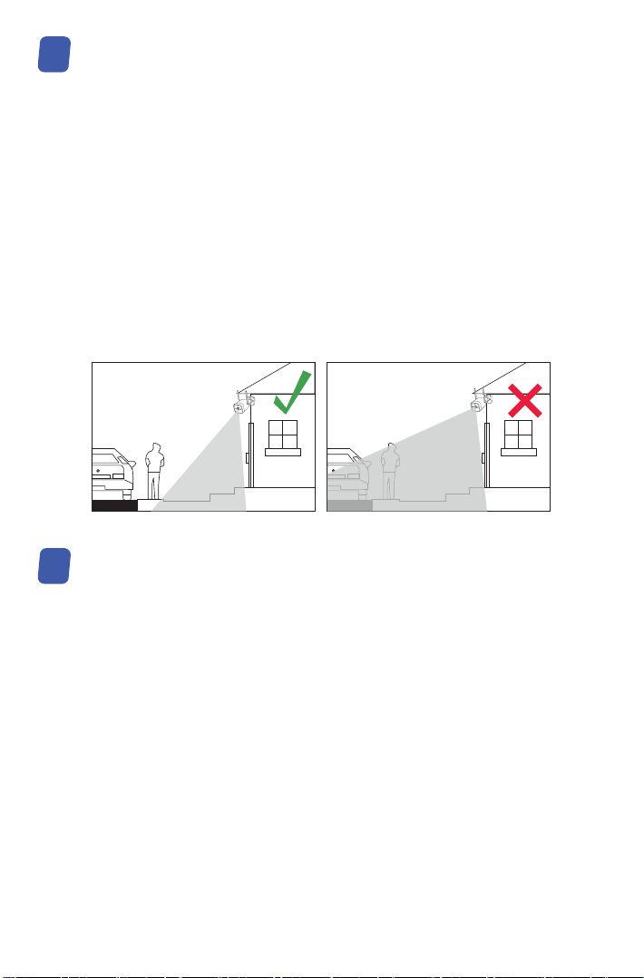
Please refer to the picture down below for the ideal installation.
It is recommended to place the camera at least 7 feet (2.1m) above the ground and tilted
slightly downward towards the monitoring area, excluding any high-traffic areas. (E.g.
sidewalks or roadways).
This product has a built-in hard drive. If you need to replace it, please choose a 3.5-inch
hard drive with a thickness of no more than 2cm.
NOTE: Please ignore it if you do not need to replace the hard disk for your video recorder.
1. Power off the video recorder and remove the sliding cover.
2. Insert the hard disk into the NVR, as shown in the figure.
3. Flip the NVR to the back and use a Phillips screwdriver to fix the hard disk.
4. Close the sliding cover of the NVR.
You need to format the hard drive before recording. Right click mouse > Main Menu > Hard
Disk Management > select Hard Disk > Format > Apply.
1. Ensure that the camera’s view is open and free of obstructions.
2. Place the camera at no more than 20 feet (6.1m) to ensure that the area you want to
monitor is within the field of view.
3. Install the camera within the receiving range of the recorder (refer to the camera
specifications).
4. The camera can be used outdoors (protection rating IP66).

06
Remote View Settings (App)
08
Remote View Settings (AVSS Client)
09
AVSS PC client can be applied to DVR/NVR/IPC monitoring, with functions such as live view,
device management, and remote video playback etc..
Make sure that the device has completed the network configuration before adding device on
PC client. Download and install the AVSS client, follow the steps below to start setup. Official
Download: https://www.zositech.com/app/.
Zosi Smart App (IOS/Android) App video operaon link
HDNetwork Video Recorder
HDD LAN POWER
HDNetwork Video Recorder
HDD LAN POWER
HDNetwork Video Recorder
HDD LAN POWER
HDNetwork Video Recorder
HDD LAN POWER
2TB
1 2
3 4

07
9.1 Login
9.2 Register
1. Click Register Now to enter
the registration page
2. Enter the unregistered account
and password to sign in
xxxxxxxxxxx
xxxxxxxxxxx
Install and open AVSS PC client, select the
language and click Login. Please register an
account first if you don’t have one. It is
recommended to log in with the account of
ZOSI Smart App, or choose local login (no
account and password is required)

9.3 Device Management
9.3.1 Click Add Device below the device list to add device information
9.3.2 Edit Device
08
Select device type: NVR/DVR/IPC, etc., enter the device name, device ID or instant identifier
ID (Drag the device QR code or sharing code into the QR Code Identification Zone), user
name, device password and channel amount, and then click Confirm to save the setup.
NOTE: The default user name is "admin", the default password of IPC is "admin", NVR/DVR
does not need to enter a password, the number of camera channels should be the number of
cameras, the default is 1.
Modify the device type, device name, device ID, channel number, login user name and
password, and save the modification.

09
Get to the device configuration.
1. Modify the login password of the device
2. Set up smart detection, WiFi
9.3.3 Device Configuration

10
9.3.4 Search Device
3. Date and time
4. Mirror mode and recording mode
Click Submit to apply after modifications.
The device and AVSS client are connected to the same LAN, and the AVSS client can search
out the information of the device.

11
Select channel to watch live streaming.
9.4 Live View
9.5 Video Playback
Live View
Playback
Click Playback, select device, channel, date, time, click the play icon to start replaying
recorded footage.

12
1. Right click the mouse, the main menu will come out.
2. Select and enter IPC Channel Config page.
New Camera Pairing
10
The cameras have been paired before leaving the factory, NVR will automatically display
video after powering on the camera system. It is recommended that users conduct a
power-on test before installation to ensure that each camera can work normally. If it fails,
please contact our customer service.
If you want to add a new camera or reset the camera, please follow the following steps. Take
out the camera, install the antenna, connect NVR and camera with a network cable. Make
sure that NVR can display normally on the monitor, and then perform the following opera-
tions:
3. Click the Search on the IPC Channel Config page to search for the corresponding IPC.
4. Double-click the searched cameras, or tick the camera and click WiFi Add. The status of
IPC connected shows at the bottom of the page, and the corresponding monitoring video will
display.

13
Warranty & Customer Service
11
NOTE: If all eight IPC channels have been connected and you need to connect other
cameras, then you will need to delete one or more channels to add other cameras.
Please kindly note that product failures caused by the following conditions are not covered
by the warranty:
1. Product failure due to accident, negligence, disaster, improper operation or misoperation.
2. Improper working environment or conditions, such as defaults due to power failure,
ambient temperature, lightning strikes, etc..
3. The product has been repaired by a maintenance not authorized by the manufacturer.
4. Product purchased over 12 months from its original purchase date.
5. The product must be purchased from ZOSI official website or authorized dealer to enjoy
warranty service.
More: https://zositech.com/ or https://www.zositech.com/support-center

14
Contenido del envío
01
4 × Cámara
1 × 12V/2A Adaptador
de corriente para NVR 1 × 1m Cable
de red
1 × Ratón USB 1 × Tapa impermeable
1 × Cable HDMI 4 × Bolsa
de tornillos
de montaje
4 × 12V/1A Adaptador de
corriente para cámara
1 × NVR 4 x Plantilla de
perforación
4 x Pegatina de
advertencia
1 × Guía de
operación rápida
Quick Start Guide
Nota: tenemos 2 kits, el kit de 4 cámaras y el kit de 8 cámaras. La cantidad de cámaras,
adaptadores de alimentación de cámara de 12V/1A, plantillas de montaje, bolsas de
tornillos de montaje y pegatinas de advertencia será la misma que la del kit de cámara
que compró. Para la tapa impermeable, hay 1 pieza en el kit de 4 cámaras y 2 piezas en
el kit de 8 cámaras.

15
Descripción del producto
02
2.1 Grabador NVR
2.2 Cámara
NOTA: NVR con disco duro admite grabación 24/7.
①Puerto VGA: conecte el monitor al puerto VGA del NVR mediante un cable VGA.
②Puerto HDMI: conecte el monitor al puerto HDMI del NVR mediante un cable HDMI.
③Puerto USB de respaldo: inserte la memoria USB para realizar una copia de seguridad
o actualizar el sistema.
④Puerto Ethernet: conecte el enrutador o interruptor al NVR mediante un cable Ethernet.
⑤Puerto USB del ratón: conecte el ratón.
⑥Puerto de alimentación: conecte el transformador.
⑦Puerto de audio: salida de señal de audio.
⑧Antena: transmite la señal Wi-Fi.
①Puerto VGA
②Puerto HDMI ⑦Puerto de audio
⑤Puerto USB
del ratón
⑥Puerto de
alimentación
④Puerto Ethernet
⑧Antena
③Puerto USB
de respaldo
①Lente: capturar imagen y video.
②Luz blanca: iluminación y alarma luminosa.
③LEDs infrarrojos: proporciona visión nocturna en
entornos oscuros.
④CDS: cambio automático de día y de noche.
⑤Micrófono: para intercomunicador por voz.
⑥Altavoz: para intercomunicador por voz y alarma sonora.
⑦Antena: transmite la señal Wi-Fi.
⑧Luz de advertencia: se enciende cuando el NVR se enciende y actúa como una advertencia.
Se puede apagar en la interfaz de configuración de alarma de luz y sonido del NVR.
①Lente ⑦Antena
⑤Micrófono
④CDS
⑧Luz de
advertencia
⑥Altavoz
③LEDs infrarrojos
②Luz blanca*2

16
¿Cómo conecta el sistema?
04
¿Cómo funciona el sistema?
03
El kit completo consta de dos partes. Una es el NVR, que debe estar conectado al monitor;
la otra es la cámara IP. El NVR y la cámara necesitan una fuente de alimentación para
funcionar. Los usuarios pueden ver videos en tiempo real capturados por cada cámara en
el monitor. Estos videos también se guardarán en el NVR para su posterior reproducción en
cualquier momento.
Para garantizar el funcionamiento correcto del producto, se recomienda encarecidamente
conectar y probar todo el sistema antes de la instalación.
Conexión del sistema:
1. Conecte el NVR al enrutador mediante un cable de red;
2. Conecte el monitor al puerto HDMI o VGA (no se incluye el cable VGA) del NVR;
3. Conecte el ratón suministrado al puerto USB superior del NVR;
4. Conecte el transformador DC12V 2A al puerto de alimentación del NVR;
5. Conecte el NVR y las cámaras a la toma de corriente utilizando los transformadores
suministrados, las cámaras y el NVR se conectarán automáticamente después del inicio;
6. El monitor mostrará el video en vivo de la cámara.

17
Instrucciones para instalar la cámara
05
1. Ajuste la antena de la cámara en posición vertical para obtener la mejor señal Wi-Fi.
2. Taladre orificios en la pared de acuerdo con la posición de la plantilla de perforación e
inserte los tacos de goma en los orificios.
3. Alinee los orificios de montaje de la cámara con los tacos de goma de la pared, luego
atornille los tornillos en los tacos de goma y apriételos.
4. Ajustelacámaraaunánguloadecuado.
4. Ajustarelángulo
3. Instalar la cámara
1. Montar la antena 2. Insertar los tacos de
goma en los orificios

18
Consejos de instalación
06
Instalación del disco duro
07
Consulte la imagen a continuación para ver la instalación ideal.
Se recomienda colocar la cámara al menos a 2,1m (7 pies) sobre el suelo y ligeramente
inclinada hacia el área de vigilancia, excluyendo las áreas de mucho tráfico (Por ejemplo,
aceras o carreteras).
Este producto tiene un disco duro incorporado. Si necesita reemplazarlo, elija un disco duro
de 3,5 pulgadas con un grosor de no más de 2cm.
Nota: omita estos pasos si su grabador no necesita reemplazar el disco duro.
1. Apague el grabador y retire la cubierta lateral deslizante.
2. Inserte el disco duro en el NVR, como se muestra en la figura.
3. Gire el NVR hacia atrás y use un destornillador Phillips para fijar el disco duro.
4. Cierre la cubierta lateral deslizante del NVR.
Debe formatear el disco duro antes de grabar. Haga clic derecho del ratón> Menú principal>
Administración de disco> Seleccione el disco duro> Haga clic en Formato> Aplicar.
1. Asegúrese de que la vista de la cámara esté abierta y sin obstrucciones.
2. Coloque la cámara a una distancia de 6,1m (20 pies) para asegurarse de que el área que
desea supervisar esté dentro del rango de visión.
3. Instale la cámara dentro del rango de recepción del grabador.
4. La cámara se puede utilizar en exteriores (grado de protección IP66).
Table of contents
Languages:
Other ZOSI Security Camera manuals