ZUBI 700 Instruction Manual

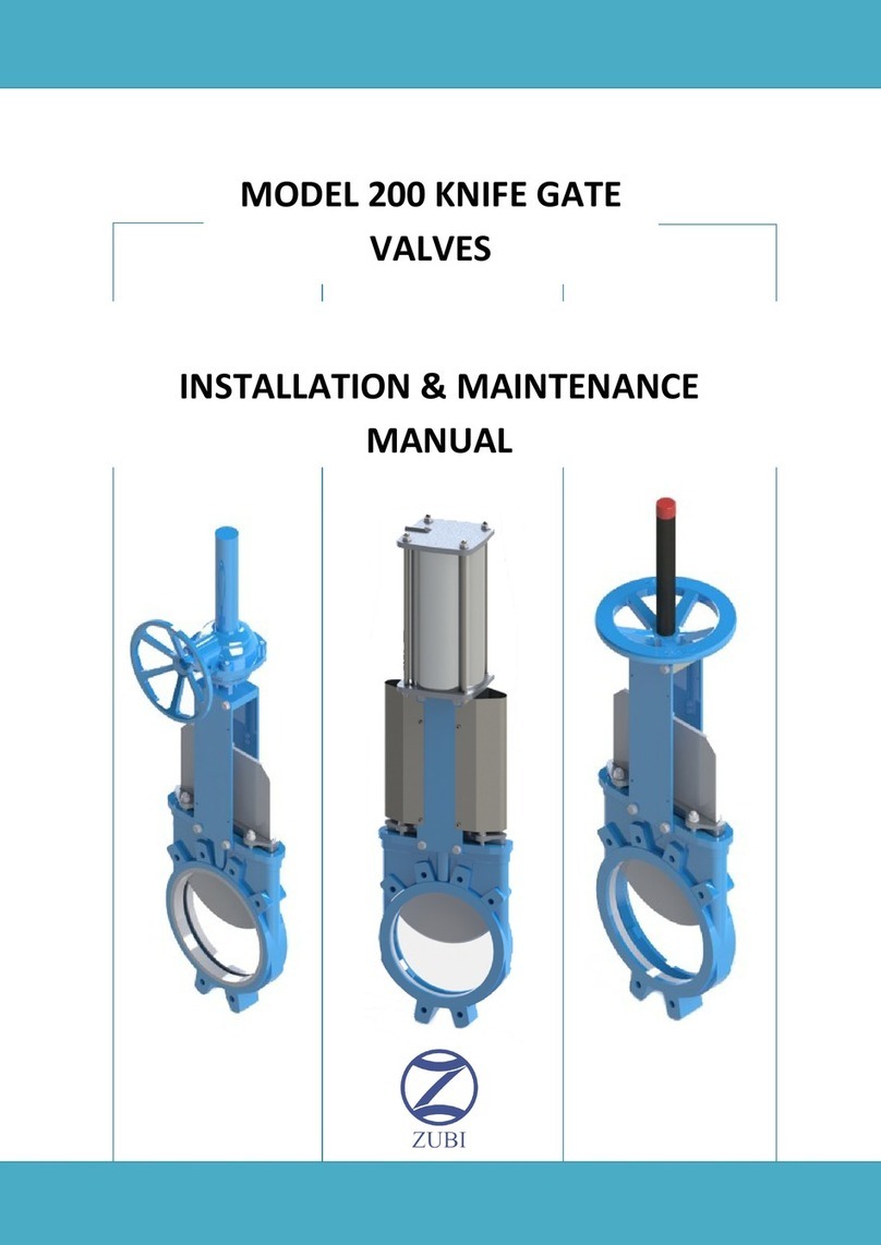
MODEL 700 KNIFE GATE
VALVES
INSTALLATION & MAINTENANCE
MANUAL

Installation & maintenance manual
Knife gate valves Page 2
Rev. 0 –12/2019
T700
Index
1. List of components / General arrangement
2. Description
3. Handling
4. Installation
5. Actuators / Operation
6. Maintenance
a. Changing the packing
b. Replacing the seat
c. Maintenance of the pneumatic cylinders
7. Recommendations
8. Storage

Installation & maintenance manual
Knife gate valves Page 3
Rev. 0 –12/2019
T700
1. List of componentes / general arrangement

Installation & maintenance manual
Knife gate valves Page 4
Rev. 0 –12/2019
T700
2. Description
The model 700 knife gate valve is bidirectional so it can be installed in either of his two
directions. The valve is commonly used for clean fluids with few suspended solids.
The Model 700 complies with the following European directives:
2006/42/CE (Machinery Directive)
2014/68/EU (PED)
3. Handling
It is important to pay attention to the following points when handling the valve.
Do not lift the valve by the actuator or by the guards as they are not designed for it, you should
use threaded eyebolts into threaded holes in the body. It is also not advised to hold the valve
through the bore of the valve as this could damage or dislodge the seat.
It is advisable to use slings for lifting and handling valves where the weight exceeds that stated
as acceptable in the Health & Safety Manual Handling Codes.

Installation & maintenance manual
Knife gate valves Page 5
Rev. 0 –12/2019
T700
4. Installation
For proper installation of the Model 700 valves it is important to consider the following:
Personnel handling and installing the valves must be trained and must comply with all
necessary safety regulations.
Prior to installation of the valve is important to inspect and verify that it has not suffered any
damage or harm during shipping and/or storage.
Make sure that the internal bore of the valve is clean and free from debris, also that the
adjoining areas where it will be installed are free from dirt, weld deposits and that the flange
facings are clean. Make sure that used gaskets are suitable.
The distance between the connection flanges must be correctly aligned and parallel, any
defects will cause difficulties in the operation. Special care should be taken to maintain the
correct distance between the flanges and to ensure that they are parallel to the valve body.
Incorrect alignment of the valve can cause deformations, which can lead to difficulties in
operation.
Tighten bolts with caution, so that tensions in the body do not cause any cracking or breaking.
As a general rule, the valve should be installed vertically on horizontal pipe. However it is also
possible to mount it in any other position as long as you consider that any actuators fitted to
the valve are adequately supported when the position is horizontal or inclined.
Once the valve has been installed and securing the flanges are tight, operate the valve under
pressure and check the seal under load. It is important to note that during transportation or
storage of the valve the gland material might have settled, so that, in the event of leak, tighten
the gland nuts gradually and in a crosswise pattern. Only tighten just enough to prevent any
leakage. If the gland is overtighten, as this reduces the life of the gland and increase the force
required to operate the valve, possibly causing damage.
5. Actuators / Operation
Hand Wheel
To open the valve turn the hand wheel counterclockwise, to shut valve turn the hand wheel
clockwise.

Installation & maintenance manual
Knife gate valves Page 6
Rev. 0 –12/2019
T700
Lever
To operate the valve, first loosen the quick release locking screw and then operate the lever in
the direction of opening or closing. To secure the position, tighten the quick release locking
lever.
Cylinder
For pneumatically operated valves, there are option for double-acting and single-acting, in
both cases the recommended air pressure is 5 to 6 bar.
We recommend dry compressed air, filtered and lubricated for proper operation and longevity
of the cylinder.
Hydraulic
Where valves are operated with hydraulic cylinders, is important to use clean hydraulic and to
maintain the cylinders on a regular basis. It is recommended specifying low temperature oils in
areas where the valves are constantly exposed to cold temperatures.
Gear-box
The operation with a gearbox is similar to the drive wheel. For best performance, it is
recommended to lubricate the gear every six months. When valves are stored, it is
recommended to operate every 4 months.
Electric
Recommended electric actuator rpm for Zubi T700 valve is 45rpm, higher speed rpm under
end user responsibility.
6. Maintenance
VALVULAS ZUBI is not responsible for any damage that may occur due to the use of non-
original components or spare parts. For any modification, consult ZUBI VALVES for advice.
The valves require a periodical minimum maintenance of the packing set and body seal. Knife
sliders need to be checked and replaced if they are in poor condition.
Shaft lubrication is highly recommended every 6 months using the lubrication point located in
the handwheel bridge.
Measures to take into account:
The installation and handling process, as well as the maintenance of the valves, must be
carried out by trained personnel using appropriate personal protection equipment (gloves,
safety shoes, etc). Release process pressure and drain process fluid from the valve, isolating
the valve from the process. Clear the area where we are manipulating the valve to avoid
accidents.

Installation & maintenance manual
Knife gate valves Page 7
Rev. 0 –12/2019
T700
Procedure:
It is important to replace the seat and packing set. The life of these elements will depend on
the working conditions of the valve such as: pressure, temperature, abrasion, chemical action,
number of operations, etc. Maintenance should be carried out as follows:
*Bear in mind that in this process we will remove the valve drive so it would be advisable to
use lifting gear if you consider it necessary.
1. First, without releasing the body from the pipe, isolate the line pressure and close the
valve. Remove (recommended) the valve from the pipeline to facilitate the process.
2. Remove the gate guards (for automatically actuated valves only). Next, the lower bolts
of the support plate to release the drive.
3. Release the shaft/gate nuts and remove top supports and actuator.
4. Loosen the gland follower studs/nuts and remove the gland.
5. Remove the packing, gate and finally the internal gate guides.
6. Pull the seat out (use some pliers if necessary)

Installation & maintenance manual
Knife gate valves Page 8
Rev. 0 –12/2019
T700
7. Once all is removed, clean the seat cavity and stuffing box area. Lubricate new U-
profile seat with synthetic lubricating grease, silicone based and install by pushing it in
from both sides.
8. Fit both HD1000 sliders (This maybe made easier using a dab of Vaseline (non
pretroleum based) on the back of the slider to keep them in place in the body cavity).
Install the knife and lubricate with synthetic lubricating grease, silicone based for
easier installation.
9. After cleaning the stuffing box area, we will install the new packing set. 45º o´ring cut
is recommended as shown in detail A.
10. Once new packing is inserted, proceed with a steady initial tightening of the gland
follower. Do not overtorque the gland, as this will reduce the life of the packing
elements and make the valve difficult to operate.
11. Fix the shaft/gate and support plates and remount the handwheel / actuator.
12. Carry out some operations with a loaded circuit to test new components and if
necessary re-tighten the gland follower to prevent leakage.
Detail A:
Slider:

Installation & maintenance manual
Knife gate valves Page 9
Rev. 0 –12/2019
T700
c) Maintenance of pneumatic cylinders
The actuators seals must be replaced if leaking is detected between the two cylinder
chambers. This leak is due to the deterioration of the seals or cylinder liner.
Complete replacement of the cylinder must be made as follows:
1. Disconnect the cylinder from the air supply with the valve in the closed position; make
sure all the air is drained out of the cylinder.
2. Loosen and remove the lower bolts on the support plates.
3. Disconnect the shaft from the gate.
4. Next, install the new drive, reconnecting the shaft to the gate.
5. Replace the support plates and tighten the bolts.
6. Operate the valve several times before placing back in line, pressurise with air not
exceeding 7 bar or less than 5, thus proving the proper functioning of the cylinder.
When replacing the cylinder components, you must follow the guidelines above as 1-2-3 then
as follows:
To renew the o-rings on the covers, undo the tie rod nuts; carefully remove cover
tapping gently upwards trying not to damage the barrel or cap. Remove old o-ring and
clean cap, insert new o-ring and replace cap. Tighten the nuts on the tie rods
diagonally.
To replace the piston, remove the upper cover and the cylinder barrel leaving the
piston exposed inside. Subsequently, undo the nyloc nut and washer holding the
piston to the piston rod, removed the damaged piston, clean thread and replace with
new piston washer and new nyloc nut.
To replace the seal cap, bottom cover came loose and scraper, leaving open the
damaged board.

Installation & maintenance manual
Knife gate valves Page 10
Rev. 0 –12/2019
T700
7. Recommendations
For proper maintenance of the valves, we recommend periodic changes as mentioned
in the valve components. Its duration will depend on the working conditions, temperature and
chemical corrosion to which they are subjected.
8. Storage
Valves should be stored in a well ventilated place at a temperature not exceeding
30ºC, especially in long-term storage, because seats & gaskets may deteriorate.
It is recommended to store the valves under cover, but if this is not possible and they
have to be stored outside, it is advisable to leave in the plastic covered crates where
the valves are delivered in and cover the crates with suitable tarpaulins.
Dynamic areas of valves, especially the shaft, must remain greased, for it, it is
important to conduct periodic inspections and grease as needed. Valves will need to
be operated to make greasing effective.

Installation & maintenance manual
Knife gate valves Page 11
Rev. 0 –12/2019
T700
ZUBI FACTORY Auzolan 2b Bajo 20303 Irun Guipuzcoa (Spain)
ZUBI OFFICES Hilanderas 5 20303 Irun Guipuzcoa (Spain)
www.valvulaszubi.com
This manual suits for next models
1
Table of contents
Other ZUBI Control Unit manuals
Popular Control Unit manuals by other brands

Weidmüller
Weidmüller AMS400A operating instructions

Emerson
Emerson Fisher N551 instruction manual

Huawei
Huawei MU609 Hardware guide

Topline
Topline TOP-FLO 77 Series Installation & maintenance manual

GEM
GEM 625 Installation, operating and maintenance instructions

Texas Instruments
Texas Instruments TRF7962A manual

Daikin
Daikin E2MV03B6 Original instructions

Monacor
Monacor ATT-1950 instructions

Bosch
Bosch Rexroth IndraControl VCP 02.2 Project planning manual

HEIDENHAIN
HEIDENHAIN PWT 101 user manual

Cinterion
Cinterion BGS3 Hardware interface description

Bell and Gossett
Bell and Gossett DB-3/4 Installation, operation & service instructions