ZURN plumbSMART Z-LIGHT-W1 User manual

LIMITED WARRANTY
All goods sold hereunder are warranted to be free from defects in material and factory workmanship for a period of three years from the
date of purchase. Decorative nishes warranted for one year. We will replace at no costs goods that prove defective provided we are
notied in writing of such defect and the goods are returned to us prepaid at Sanford, NC, with evidence that they have been properly
maintained and used in accordance with instructions. We shall not be responsible for any labor charges or any loss, injury or damages
whatsoever, including incidental or consequential damages. The sole and exclusive remedy shall be limited to the replacement of the
defective goods. Before installation and use, the purchaser shall determine the suitability of the product for his intended use and the
purchaser assumes all risk and liability whatever in connection therewith. Where permitted by law, the implied warranty of merchantability
is expressly excluded. If the products sold hereunder are “consumer products,” the implied warranty of merchantability is limited to a
period of three years and shall be limited solely to the replacement of the defective goods. All weights stated in our catalogs and lists
are approximate and are not guaranteed.
NOTICE: READ ENTIRE MANUAL PRIOR TO INSTALLING PRODUCT.
Z-LIGHT-W1
Zurn Smart Occupancy Light
Installation,
Operation,
Maintenance
and
Parts
Manual
Patented and Patents Pending
WARNING: Cancer and Reproducve Harm - www.P65Warnings.ca.gov
ADVERTENCIA: Cáncer y daño reproducvo - www.P65Warnings.ca.gov
AVERTISSEMENT: Cancer et eets néfastes sur la reproducon - www.P65Warnings.ca.gov
For Commercial and Institutional Use Only

This Page Intentionally Left Blank

FCC REQUIREMENTS FOR OPERATION IN THE UNITED STATES
FCC Information for the User
This product does not contain any user serviceable components and is to be used with ap-
proved, internal antennas only. Any product changes of modications will invalidate all applica-
ble regulatory certications and approvals.
FCC Guidelines for Human Exposure
This equipment complies with FCC radiation exposure limits set forth for an uncontrolled en-
vironment.This equipment should be installed and operated with minimum distance of 20 cm
between the radiator and your body. This transmitter must not be co-located or operating in
conjunction with any other antenna or transmitter.
Federal Communication Commission Statement
This device complies with Part 15 of the FCC Rules. Operation is subject to the following two
conditions: (1) this device may not cause harmful interference, and (2) this device must accept
any interference received, including interference that may cause undesired operation.
FCC Radio Frequency Interference Warning and Instructions
This equipment has been tested and found to comply with the limits for a Class B digital de-
vice, pursuant to Part 15 of the FCC Rules. These limits are designed to provide reasonable
protection against harmful interference in a residential installation. This equipment uses and
can radiate radio frequency energy and, if not installed and used in accordance with the in-
structions, may cause harmful interference to radio communications. However, there is no
guarantee that interference will not occur in a particular installation. If this equipment does
cause harmful interference to radio or television reception, which can be determined by turning
the equipment o and on, the user is encouraged to try and correct the interference by one or
more of the following methods:
• Increase the separation between the equipment and receiver.
• Connect the equipment into an outlet on a circuit dierent from that to which the receiver is
connected.
• Consult the dealer or an experienced radio/TV technician for help.
FCC Caution
Any changes or modications not expressly approved by the party responsible for compliance
could void the user’s authority to operate this equipment.
Zurn is not responsible for any radio or television interference caused by using other than
specied or recommended cables and connectors or by unauthorized changes or modications
to this equipment.
Responsible party: ZURN INDUSTRIES, LLC 511 W. Freshwater Way, Milwaukee, WI U.S.A.
53204 · Ph. 1-855-ONE-ZURN, Fax 919-775-3541

INDUSTRY CANADA
This device complies with RSS-247 of the Industry Canada Rules. Operation is subject to the
following two conditions: (1) this device may not cause harmful interference, and (2) this device
must accept any interference received, including interference that may cause undesired opera-
tion.
Ce dispositif est conforme à la nor me RSS-247 d’Industrie Canada applicable aux appareils
radio exempts de license. Son fonctionnement est sujet aux deux conditions suivantes: (1) le
dispositif ne doit pas produire de brouillage préjudiciable, et (2) CE dispositif doit accepter tout
brouillage reçu, y compris un brouillage susceptible de provoquer un fonctionnement indésir-
able.
Radiation Exposure Statement
This equipment complies with ISED radiation exposure limits set forth for an uncontrolled
environment.This equipment must be installed and used with a minimum distance of 10 mm
between the radiator and your body.
NOTE IMPORTANTE: Déclaration d’exposition aux radiations:
Cet équipement est conform aux limites d’exposition aux rayonnements ISED établies pour un
environment non contrôlé. Cet équipement doit être installé et utilisé avec une distance mini-
male de 10 mm entre le radiateur et votre corps.
FCC ID: 2AY4MZURNOL
IC ID: 27057-ZURNOL

FV781 Rev. A 10/14/21
Page 1
Zurn Smart Occupancy Light Part List
Recommended Tools
Extension
Pole (If ordered)
Mounting
Bracket
Occupancy
Light
Screwdriver
Applicable Screw
For installing surface
#8 or M4
Anchor
(Optional)
Hand Drill
1/2”, 7/64”
Drill Bits

FV781 Rev. A 10/14/21
Page 2
Prepare for Installation
AC
DC
Verify Installation Height and Placement
Each light unit should be installed at a maximum height of 8’6”,
as measured from the oor to the mount or base of the light, to
provide best detection accuracy. A Zurn Smart Occupancy Light
Mount - Extension Pole should be utilized for ceiling heights over
8’6”.
The recommended installation for each light unit is 6” inside the
stall door without any visual obstructions within the light unit’s 60
degree eld of view. Any deviation from recommended installation
placement and height may impact product accuracy.
Ceiling
8’6”
Partition
Floor
Wiring Diagram
Breaker
Panel
Zurn Z-PWRSUP-W1
Power Supply
Enclosed
Junction box
Occupancy
Light
Insert
into
12 VDC
* Zurn Smart Occupancy Light should be mounted at a max 8’6”
feet above the oor, either directly to the ceiling or using a Zurn
Smart Occupancy Light Mount - Extension Pole.
120 VAC

FV781 Rev. A 10/14/21
Page 3
Power Supply
Wiring
Gateway - LTE or Ethernet
The Zurn Z-PWRSUP-W1 provides screw terminals for the
purpose of connecting to both the upstream 120VAC branch
circuit and the downstream low-voltage DC (Class II) circuit. To
protect these live contacts, the power supply should be installed
in an appropriate enclosure including all recommended cable
clamps, conduit connectors, etc. in accordance with applicable
local electric code.
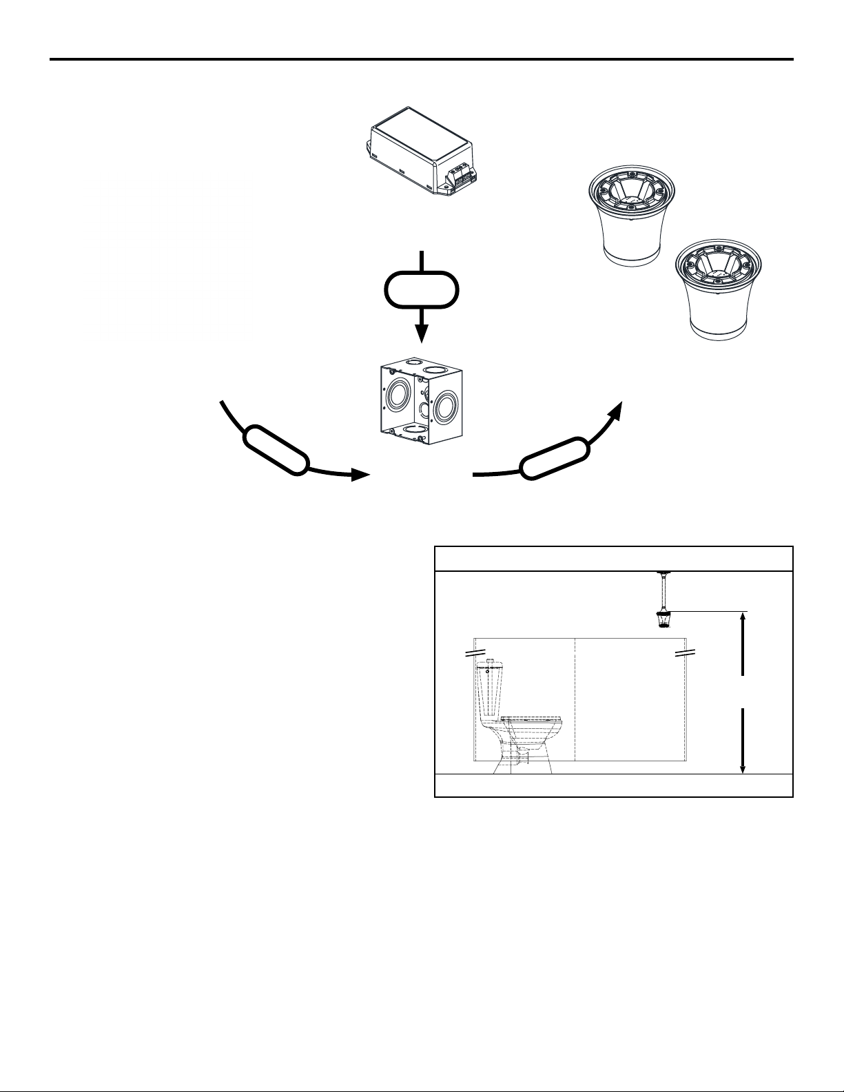
The supply will t diagonally into a standard 4-11/16” square
metal junction box. A 6” square metal junction box is sucient to
house two supplies side-by-side if necessary. Ensure the supply
is securely mounted within its enclosure so that shifting cannot
occur.
Dimensions: 2 1/8” W x 4 3/8” L x 1 5/16” H
Important: The Z-PWRSUP-W1 power supply is not for
residential or consumer use. Please install junction box and
power supply in dry locations only.
Each Zurn Smart Occupancy Light consumes a maximum of 150mA; a run of 40 lights, for example, would consume a maximum of
6A. Zurn recommends wiring the downstream low-voltage DC circuit (from power supply to light) using plenum-rated 2-conductor cable
sized according to the overall distance and maximum current load in accordance with applicable local electric code. Voltage drop in
the overall run must not exceed 1V at max load. Do not exceed 6A (40 lights) of total load per supply. If using stranded wire, Zurn
recommends using appropriately sized crimp-on ferrules at all terminations to ensure connection integrity and to prevent accidental
short-circuit conditions.
Power
Connect the ZGW-WRP-W1-LTE or ZGW-WRP-W1-ETH
gateway to a standard wall socket using the included power
supply as shown on the right.
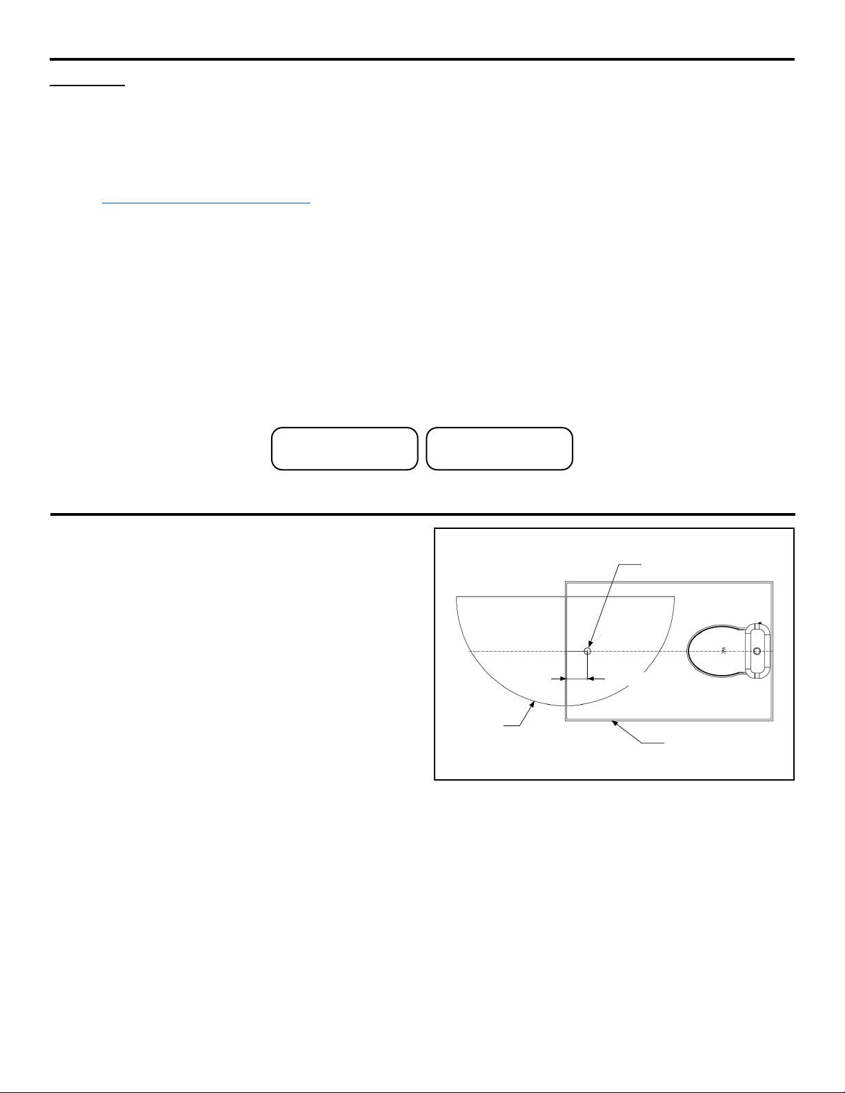
Placement
LTE Gateway: The ZGW-WRP-W1-LTE wireless gateway uses
a cellular wide-area-network connection. To improve quality,
place the gateway away from large metallic structures or sources
of signicant electrical interference like large transformers,
motors, or orescent lighting ballasts.
Ethernet Gateway: The ZGW-WRP-W1-ETH gateway requires
connection to an Ethernet cable. Ethernet port is adjacent to the
power connection on the gateway.
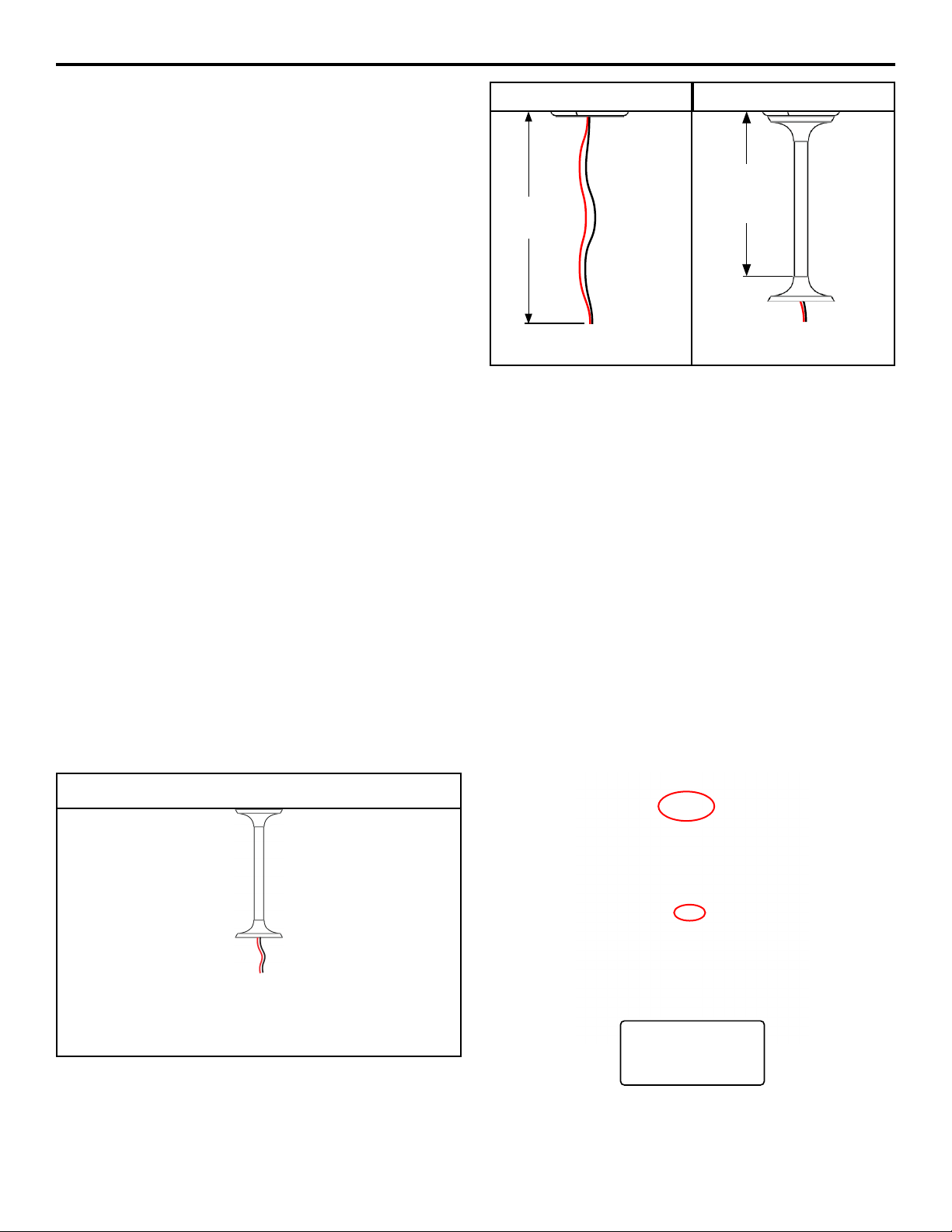
Zurn Smart Occupancy Lights: The Zurn Smart Occupancy Light system uses wireless mesh communication. Zurn Smart
Occupancy Lights will communicate wirelessly with the gateway; if necessary, they will use another Zurn Smart Occupancy Light as
a relay. The gateway should be located no more than 60ft away from the nearest Zurn Smart Occupancy Light, and no Zurn Smart
Occupancy Light should be located more than 60ft away from either a gateway or another Zurn Smart Occupancy Light relayed to the
gateway via wireless mesh network.
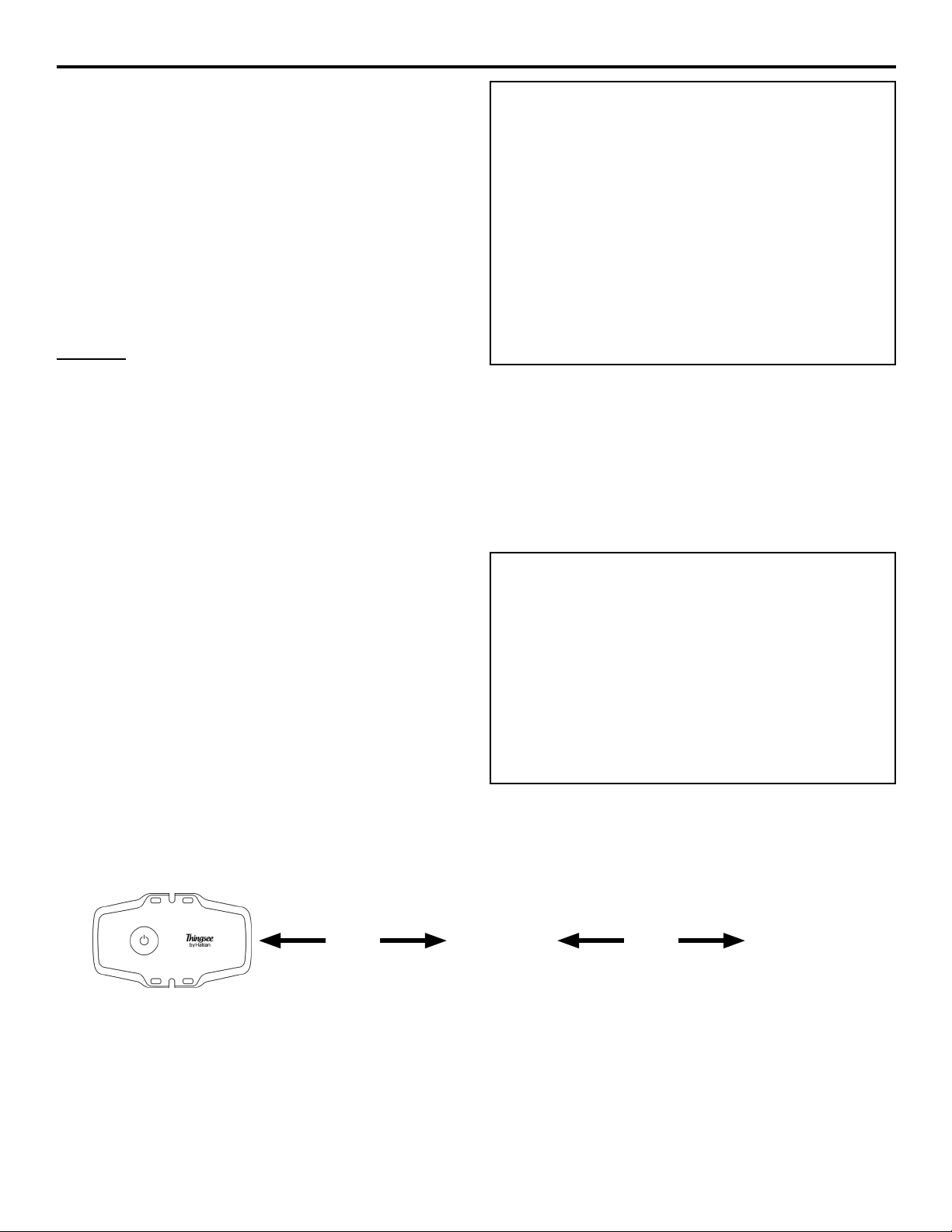
Setup
On connection to power, the gateway will attempt to connect rst to the cellular or Ethernet network, then to the cloud.
Blinking Red – Attempting to connect to Cellular or Ethernet network
Blinking Red/Green Simultaneously – Cellular or Ethernet connected, attempting to connect to cloud
Blinking Green – Connected and operating correctly (Cellular LTE only)
Solid Green – Connected and operating correctly (Ethernet only)
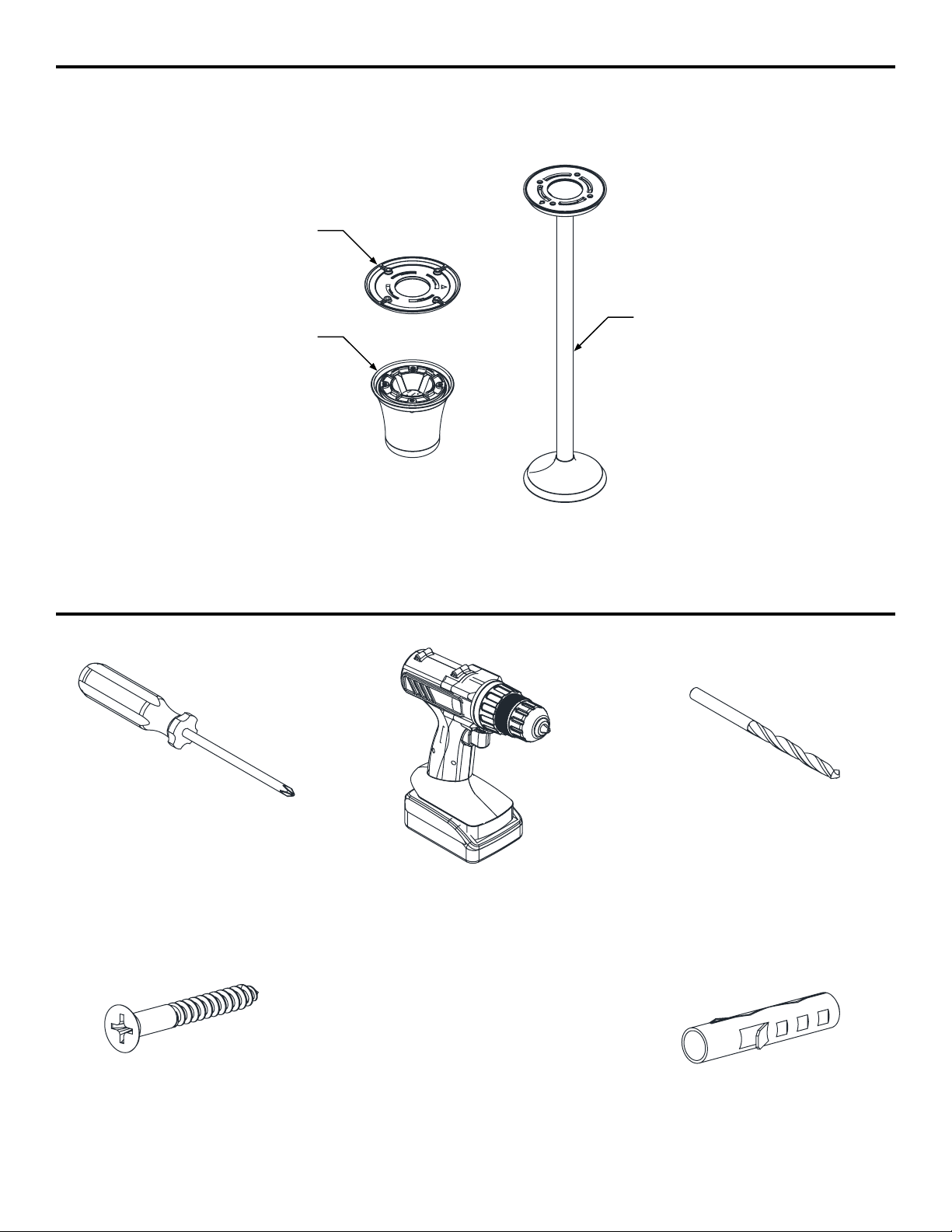
Install and Setup Your Power Supply and Gateway
< 60 ft < 60 ft
Power connection of ZGW-WRP-W1-LTE Gateway
At least one Zurn Smart
Occupancy Light should be
located within 60ft of the
gateway.
Each Zurn Smart Occupancy
Light should be located within
60ft of another light or the
gateway.
Not for residential or consumer use

FV781 Rev. A 10/14/21
Page 4
Install Your Zurn Smart Occupancy Lights
Step 1
First, nd the center of the doorway in the relation to the ceiling
that you intend on mounting the light to. Once you have located
the center of the doorway you will need to measure out from the
center line by approximately 6 inches to the inside of the stall,
from the center point of the doorway. See image on the right.
Drill a 1/2” hole in the ceiling surface to allow for the power
cables to run though.
Door
Swing
Radius Partition
Center Line
Light Cable Hole
6”
Important: The below registration instructions are provided for use of the Zurn plumbSMART™
portal. If you are connecting lights into a 3rd party portal, please consult your sales representative for
registration instructions and skip to the Install Your Zurn Smart Occupancy Lights section.
Note: You may install and register your Zurn Smart Occupancy Lights prior to receiving a gateway. However, you will not
be connected to the plumbSMART™ portal until you install your gateway. Please follow the instructions below to contact
Zurn prior to registering your devices.
Connecting to the plumbSMART™ Portal
1. Visit www.zurn.com/plumbSMART-connect to save time and money on your installation.
You can also call us at 844-987-6737.
2. Provide the serial number and contact name, email address, and basic information about the installation site.
3. We will activate your plumbSMART™ account, set up your enterprise, and give you guidance on how to register each connected
product as you install it.
4. We will send a conrmation email with a link, or you can go to plumbsmart.zurn.com to log into your plumbSMART™ account for
the rst time.
5. Add other users and installers to your plumbSMART™ account.
6. Make sure you and/or your installers have the plumbSMART™ mobile app, which you can download from the iPhone App Store or
Google Play.
7. Using the mobile app, scan or enter the serial number to register and locate each connected plumbing product as you install it.
8. Watch the how-to videos in the plumbSMART™ portal’s support section if you get stuck, or call us at 844-987-6737 for support.

FV781 Rev. A 10/14/21
Page 5
Step 2
When installing the ceiling mount bracket, it is very
important to ensure that the arrow is pointing toward the
inside of the stall, perpendicular to the stall door. In most
cases, the arrow should be pointing directly towards the
water closet. In some dierent stall congurations, such as
handicapped/ADA stalls, the arrow may not point directly
towards the water closet.
Once you have the arrow pointing towards the inside of the stall,
secure the ceiling mount bracket in-place with 4 x #8 screws or 4
x M4 screws. Be careful not to over-tighten the screws to mitigate
any ceiling or mount damage.
6”
Arrow
Pointing
Perpendicular to
Stall Door
Inside of stall door
Door
Water
Closet
The ceiling mount will come with a ‘WC’ sticker indicating the
direction of the arrow, allowing the angle of orientation to be
checked when the extension tube is in place.
Ceiling Bracket Mount Bottom EndcapExtension Tube (If used)
Each component that makes up an occupancy light has a small triangle. This triangle is a arrow that marks the direction of the sensor
beam. The arrow should always point towards the inside of the stall that the light is being installed for.

FV781 Rev. A 10/14/21
Page 6
Ceiling
Cable
Length
Ceiling
Ceiling
Extension
Tube
Length
Step 3
It is crucial that the cables you install are longer than the
extension tube that is being used. Ideally the length of the wires
should be 4 inches longer than the extension tube to make the
installation easier when connecting to the power block.
Step 4 - If Using Zurn Smart Occupancy Light Mount / Extension Pole
The ceiling mount bracket is now installed and it’s time to assemble the unit.
If using a Zurn Smart Occupancy Light Mount - Extension Pole, feed the power cables though the extension tube until you see them
visibly protruding out of the bottom extension cone.
Orient the extension pole mount (arrow located in the bottom of the extension cone) to an 11 o’clock position with the ceiling mount
bracket arrow already installed at a 12 o’clock position on the ceiling. Twist the extension tube onto the ceiling mount until the arrow
points towards the inside of the stall.
The arrow on the exposed end of the extension pole can be lined up with the WC sticker by rotating the tube when attached.
Installed
Light Mount /
Extension Pole

FV781 Rev. A 10/14/21
Page 7
Step 5
Connect the power block to the cables.
The power block is located inside the top of the Zurn Smart
Occupancy Light. Both connections are linked so either side can
be used for a single light or both sides when daisy chaining the
lights o a single power supply.
Note: When daisy chaining multiple lights o one power supply,
each light must be installed to maintain electrical connection
for the entire network of lights. If a light needs to be replaced, it
is best to remove the old light when a new one is available for
replacement. You may alternately install multiple lights using a
hub and spoke method.
Note: The dip switch on the bottom in the image is not currently
used.
+12v
+12v
0v
Dip Switch
0v
Daisy Chain Installation Option

FV781 Rev. A 10/14/21
Page 8
Step 7
Finished
Turn on power to the light. When powered up, the light will cycle
from blue to green. Once it has completed this cycle, the light
should be operational.
Finish by removing the stickers when the light has been tested
and is functioning correctly.
Your occupancy light is ready to use.
Note: If setting up an Occupancy Display, go to the Activate Your
Occupancy Display section at the end of this manual for further
instruction.
Ceiling
Step 6
Once the cables are secured into the power block, attach the light unit to the bottom of the light mount / extension pole or ceiling mount
bracket. If using a light mount / extension pole, ensure that you are holding the extension tube when twisting on the light unit to prevent
any misalignment from assembly.
IMPORTANT: Orient the indented arrow on the bottom of the light at an 11 o’clock position with the ceiling bracket arrow alread
installed at a 12 o’clock position. Twist the light until it points into the stall. You may not need to fully twist the light into the mount to
achieve the correct alignment.
Ceiling
Completed
Installation

FV781 Rev. A 10/14/21
Page 9
Activate Display Option in plumbSMART™
Link Your Display to plumbSMART™
Activate Your Occupancy Display
Step 1
After logging into plumbSMART™,
select Admin from your account pull-
down menu.
Step 2
Select Buildings on the left menu and
navigate to the desired room.
Step 3
Toggle “Enable Signage Page” slider
and click “Update” button.
Step 2 Step 3
1. Power on your television monitor and complete default setup prompts, as needed.
2. Choose option to setup network settings.
3. Select “Settings”, “EzSetting”, “Play via URL” (or equivalent).
4. Navigate to https://plumbsmart.zurn.com/display/activate.
5. Save URL.
6. Device will ask to reboot to apply settings. Select “Yes”.
7. Follow on screen instructions:
a. Navigate to https://plumbsmart.zurn.com/admin/displays on your computer, phone, or tablet.
b. Enter the displays unique activation code.
c. If activation takes longer than 2 minutes, reload the web page on your computer and get a new code from the display.
8. Select your restroom from the list on the display or on the computer.
9. Done!
Note: If the television monitor fails to display properly or has been unregistered in plumbSMART™, please restart the display and
repeat the instructions, as necessary.
Step 1

FV781 Rev. A 10/14/21
Page 10
Trouble Shooting
Problem Possible Cause Corrective Action
One or more lights in a
chain do not turn on when
power is applied
Incorrect Wiring Polarity Devices wired incorrectly will not be damaged, but will not power on.
Daisy-chained devices downstream of the polarity inversion may also
not function.
Verify wiring polarity matches markings on power input terminals.
Short Circuit Power supply Z-PWRSUP-W1 is protected against short circuit
conditions and will automatically disable power output when such a
condition is detected. If this is the case, no devices attached to the
short-circuited supply will function.
Beginning with the power supply and working down the chain of lights,
inspect power terminals for stray wires or other material causing
a short circuit. Zurn recommends use of crimp-on ferrules for all
connections when using stranded wire.
Light appears unexpectedly
dim and/or light appears
to turn o when green is
expected
Low Voltage Measure input voltage at xture and ensure voltage is between 11.4 V
and 12.6V.
If voltage measured is out of range, measure voltage at power supply
and ensure output is within range stated above.
If supply voltage is within range, ensure wiring used is sucient to
carry max current (150mA * total # of lights) per local code (excessive
voltage drop may be caused by insucient wire gauge).
If voltage at supply is low, disconnect lights from output terminals at
power supply and measure open-circuit voltage.
If open-circuit voltage is normal, inspect downstream wiring and
connections for possible short-circuit conditions.
If open-circuit voltage is low, replace power supply.
One light in a chain does
not turn on when power is
applied
Damaged Device Measure voltage at device power input terminals. If voltage is nominal
and device does not power on, replace device.
Light does not correctly
change to indicate
occupancy status
Device not oriented correctly Ensure small arrow on the bottom of the light (near sensor opening)
points into stall.
Device mounted too high Zurn recommends the mounting surface of the light be at most 8’6”
from the oor. Ensure device is installed at correct height.
Device not communicating
to cloud
Device too far from gateway or another light Ensure device is within 60ft of another light or gateway.
Gateway has no internet connection Follow troubleshooting steps for gateway below.
Gateway not installed Ensure LTE or Ethernet gateway is installed, powered on, and within
range (60ft).
Gateway not connecting to
internet
LTE Gateway: Insucient cell service Move gateway to a more optimal signal location. Ensure it is placed
above ground level and away from large metal objects or any electrical
equipment that could cause interference.
Ethernet Gateway: Network conguration Check with network administrator to ensure device is not being blocked
or blacklisted.
Gateway uses TCP ports 80, 443, and 8883 and UDP ports 53 and
123.
For further assistance with troubleshooting, visit http://www.zurn.com/

This Page Intentionally Left Blank

US 1.855.ONE.ZURN CANADA 1.905.405.8272
ZURN.COM
ZURN INDUSTRIES, LLC
511 W. Freshwater Way, Milwaukee, WI U.S.A. 53204 · Ph. 1-855-ONE-ZURN, Fax 919-775-3541
In Canada: ZURN INDUSTRIES LIMITED
7900 Goreway Drive, Unit 10, Brampton, Ontario L6T 5W6, Ph. 905-405-8272, Fax 905-405-1292
Rev. A Date:
10/14/21
C.N. No. 143368 Prod. | Dwg. No. FV781
Table of contents