ZURN AquaSense AV ZEMS Series User manual

LIMITEDWARRANTY
Allgoodssoldhereunderarewarrantedtobefreefromdefectsinmaterialandfactoryworkmanshipforaperiodoffiveyearsfromthedateof
purchase.Decorativefinisheswarrantedforoneyear.Wewillreplaceatnocostsgoodsthatprovedefectiveprovidedwearenotifiedinwriting
of such defect and the goods are returned to us prepaid at Sanford, NC, with evidence that they have been properly maintained and used in
accordancewithinstructions.Weshallnotberesponsibleforanylaborchargesoranyloss,injuryordamageswhatsoever,includingincidental
orconsequential damages. Thesoleand exclusiveremedyshall be limitedto the replacementof the defectivegoods. Before installationand
use,thepurchasershalldeterminethesuitabilityoftheproductforhisintended useandthepurchaserassumesallriskandliabilitywhatever
inconnectiontherewith.Wherepermittedbylaw,theimpliedwarrantyofmerchantabilityisexpresslyexcluded.Iftheproductssoldhereunder
are “consumer products,” the implied warranty of merchantability is limited to a period of three years and shall be limited solely to the
replacementofthedefectivegoods.Allweightsstatedin our catalogs and lists areapproximateandarenotguaranteed.
AquaSense AVTM
ZEMS Series
Automatic Systems Sensor-Operated
AquaVantage Flushometer
Installation, Operation, Maintenance
and Parts Manual
Patented and Patents Pending
Sensor-Operated Concealed Systems
ZEMS6140AV
ZEMS6142AV
ZEMS6152AV
ZEMS6190AV
ZEMS6195AV
ZEMS6197AV
Sensor-Operated Exposed Systems
ZEMS6000AV
ZEMS6000AV-2
ZEMS6000AV-3
ZEMS6001AV
ZEMS6003AV

FV38 Rev. D 2/27/12
Page 2
Model ZEMS6000 Models ZEMS6000-2 and ZEMS6000-3
Valve Rough-In
Model ZEMS6140 Model ZEMS6142
Model ZEMS6152 Models ZEMS6001 and ZEMS6003
SENSOR BOX
FINISHED WALL
41
4[108] MAX.
21
4[57] MIN.
111
2
[292]
21
[533]
43
4
[121]
TOP OF
FIXTURE
103
4[273] MAX.
33
4[95] MIN.
AS SPECIFIED
21[533]
141
2[368]
43
4
[121]
1" I.P.S.
SUPPLY
MOTOR
ACTUATOR

FV38 Rev. D 2/27/12
Page 3
PRIOR TO INSTALLATION
Prior to installing the Zurn Automatic Sensor-equipped
Flushometer, install the items listed below as illustrated in
Figures 1 through 3.
• 2-gang electrical box (4 x 4 x 2 1/8, use Steel City #52171-N
box, and #52-C-18 device cover or equivalent for sensor
with closet installs, or #52-C-14 reducing device or
equivalent for sensor with urinal installs);
• Single-gang electrical outlet for plug-in power converter.
• Electrical wiring to the power converter outlet (120 VAC, 35
watts service required for each power converter used).
• Closet fixture.
• Zurn carrier system, Z1200 series or equal.
IMPORTANT:
• All electrical wiring is to be installed in accordance with National/Local codes and regulations.
• All plumbing is to be installed in accordance with applicable codes and regulations.
• Water supply lines must be sized to provide an adequate volume of water for each fixture.
• Flush all water lines prior to making connections.
• Sensor units should not be located across from each other or in close proximity to highly reflective surfaces.
• Control Stop should never be opened to allow flow greater than fixture is capable of evacuating. In the event of valve failure,
fixture must be able to handle a continuous flow.
Model ZEMS6190 Model ZEMS6195
Model ZEMS6197
3
4[19]
VACUUM
BREAKER
TUBE
131
2
[343] 4
[102]
43
4
[121]
MOTOR
ACTUATOR
SENSOR
3
4" I.P.S.
SUPPLY
103
4[273] MAX.
33
4[95] MIN.
AS SPECIFIED
TOP OF
FIXTURE
3
4[19]
VACUUM
BREAKER
TUBE
131
2
[343]
10
[254]
43
4
[121] MOTOR
ACTUATOR
SENSOR
3
4" I.P.S.
SUPPLY
103
4[273] MAX.
33
4[95] MIN.
AS SPECIFIED
TOP OF
FIXTURE

FV38 Rev. D 2/27/12
Page 4
Notes:
1. Failure to observe proper polarity will result in faulure of
the sensor and/or power converter.
2. Use #18 AWG for interconnections.
Electrical Hook-up (Figure 1)
Be certain power is off to prevent damage to electrical components. Connect the sensor to the actuator and power converter
exactly as shown in Figure 1.
Double check that power converter polarity is correct.
Figure1
ACTUATOR
BRN
GRN
BLU
BRN
GRN
BLU
PB
PB
PB
ACTUATOR
ACTUATOR
SENSOR
SENSOR
SENSOR
HW6
(-)
BLACK
BLACK/WHITE STRIPE
(+)
PLUG-IN POWER
CONVERTER
120 VAC IN
6 VDC OUT
MANUAL OVERRIDE
PUSHBUTTONS
(-)
(+)
Electrical
AC/DC Power Supply
Install hardwired power supply or receptacle for the Zurn Power Converter in a convenient location. An optional mini junction
box (P6000-MJ) is recommended to distribute power to each sensor location. It is also recommended that brown wire be used
for the DC positive (+) of the supply and blue wire be used for the DC negative (-) of the supply. This matches the sensor and
actuator wire colors.
NOTE: One Zurn P6000-HW6 or P6000-PC6 Power Converter can operate as many as eight Automatic Sensor equipped
Flushometers. The Power Converter is supplied with a six-foot cord. If additional wire is needed from the Power Converter to
the Flushometer(s), use #18AWG for this (by others). Do not supply power to the Power Converter until installation of actuator,
sensor and Flushometer is completed and checked. Proper polarity must be observed or damage to one or all components
will result.
Maximum of
8 actuators
allowable
P6000-MJ
Optional Mini
Junction Box
Figure 2
(Power Distribution)
RED
VDC BLUE
GND
CAUTION:
RISK OF EL ECT RIC SH OCK
DRYLOCATIONUSEONLY
R
REGULATEDPOWER SUPPLY
PARTNO : 2000970 01
MODELNO : P 6000-HW6
I/P: 120 VAC/320mA@Full load, 60Hz
O/P:+ 7.6.0VDCmin@2Aload
DUTYCYCLE : 2 sec "On", 60 sec "Of f"
Delta Electronics (T hailand) Pub licCo. ,Ltd.
7.6VDC
OUT
BLACK
BLACKwith
WHITESTRIPE
BLUE(-)
RED (+)
WHITE
BLACK
120VAC
IN
P6000-HW6 WIRING
TOFAUCET
ORF LUS H VA LVE
E323168
MADE IN T H AIL AND
CUS
UL
®
"Use Co ppe r c ond uc to r o nly a nd
seedetails ininstructioin manual"
"For Gr oun din g C o ndu cto r, U se 18
AWGminimum"
WARN IN G :
Toreduceriskoffireor electric
shock-Do notinterconnect
outputterminations.
SENSOR AND
4 X 4 BOX
MOTOR
ACTUATOR
HW6
FIXTURE
BOX CLAMP
CABLE
ARMOR
FINISHED WALL
120VAC/60Hz
Service
P6000-HW6

FV38 Rev. D 2/27/12
Page 5
Override Button
on closet models only Override Button assembly. (Yoke
offset extends into device cover)
Zurn “ZEMS” Sensor
(Install horizontally for
closent models, install
verticallyfor urinal models)
Closet Installation
(Shown with cover removed)
Urinal Installation
(Shown with cover removed)
Frontsurface of device cover
to be flush with finished wall
Figure 3
Sensor Installation
Closet Models: Install plaster ring so screw holes are on left and right side of box (as shown in Figure 3). Trim tiles to allow
screw holes in plaster ring to show.
Urinal Models: Install reducing cover so screw holes are on top and bottom side of box (as shown in Figure 3). Trim tiles to
allow screw holes in plaster ring to show.
STEP 1 – Locate sensor box
Locate sensor box in the wall according to model number as shown on pages 2 and 3.
STEP 2 – Mount Automatic Sensor (Figure 3)
Install the Zurn Automatic Sensor into the 2-gang electrical box using two (2) long screws provided. Ensure that wires from
sensor case point up for closet installs and point to the right for urinal installs. The rubber push caps will be on the left side
of the sensor for closet and at the top for urinal (See Figures 4 and 4A). The sensor lens faces outward from the finished wall.
STEP 3 – Mount Yoke and Override Button (Figure 4)
Install inner nut, bracket and sealing boot on threaded shaft of override push button. Mount bracket to yoke. Adjust the distance
so that the override push button will protrude through the wall plate using the nuts on each side of bracket. Wire the override
push button as per Figure 1. Mount the assembled yoke to the electrical box.
Inner Nut
Yoke
Sealing
Boot
Bracket
Override
Button
Figure4
(Closet)
DeviceCover
#52-C-18 DeviceCover
#52-C-14
4 x 4 x 2 1/8
2 Gang Electrical Box
#52171-N
4 x 4 x 2 1/8
2 Gang Electrical Box
#52171-N
Figure4A
(Urinal)

FV38 Rev. D 2/27/12
Page 6
A. Install stop valve assembly using sweat solder adapter
kit if applicable. Thread sealing compounds should
be used on male NPT threads only.
E
C
D
B
Attach Valve Body to Stop Valve
1.) Before the supply water is turned on, be sure all stop valves
are closed off tight. The stop valves can be opened and
closed by using the adjusting screw located at the center of
the stop valve cap. Stop valve adjustments can only be
made by using the adjusting screw. It is not necessary to
remove the stop valve cap (F) when making adjustments.
If for any reason it becomes necessary to remove the
stop valve cap, be certain the water is shut off at the main
supplyvalve.
2.) Prior to inserting the flush valve tailpiece (B) into stop valve
(A), be certain that the O-ring seal (C) is located in O-ring
seal groove at the end of the tailpiece and that the locking
nut (D) and locking snap ring (E) are located as shown.
Care should be taken not to damage the O-ring when in-
serting the tailpiece into the stop valve. If lubrication is
needed, wetting the O-ring with water will be sufficient.
3.) Insert the flush valve tailpiece (B) into the stop valve (A) and
hand tighten the lock nut (D) to the stop valve. Level the
entire unit.
When all stops are connected to the water supply and
water pressure is available, flush the supply piping to
remove dirt, metal chips, etc., from system.
A
A. Before the valve is installed, open each stop fully for a
brief time and catch the water in a two gallon or larger
bucket. For multiple installations, start with the stop
valve closest to
the water supply
and work toward
the most remote
valve.
B. Due to the small
passages and
orifices, it is not
possible to
flush the piping
through the low
volume valve.
C. Once the lines
are flushed, the
valve can be
installed.
Step 1 Step 2
Step 3
Figure 5
Figure 7
Figure 6
Mechanical
The AquaVantage®design is optimized to operate between 25 and 80 psi (172 to 552 kPa) of water pressure (running). The
minimum pressure required for the valve to work properly is determined by the fixture selected. Please consult fixture manufacurer
for water pressure requirements. Protect the chrome or special finish of this flushometer during installation. Do not use toothed
tools to install or service the valve as this will damage the finish. Also, see “Care and Cleaning” section of this manual.
F

FV38 Rev. D 2/27/12
Page 7
Selection switches
(Shown in Factory
Position for closet
installs)
Selection switches
(Shown in Factory
Position for urinal
installs)
Green
(Flush Signal)
Blue (-)
Brown (+)
Sensor Cover
ResetButton
Rubber Push
Caps
Range
Adjustment
Figure 11
MODEL ADIM
ZEMS6000 10 1/8
ZEMS6000-2 22 5/8
ZEMS6000-3 25 5/8
Figure10(Exposed System)
FLUSH VALVE C
L
TOP OF
FIXTURE
Install Vacuum Breaker Flush Connection
Models ZEMS6000, ZEMS6000-2, ZEMS6000-3, ZEMS6001,
and ZEMS6003
Slide the tube nut (H), spud nut (G), slip gasket, rubber gasket
and spud escutcheon over the vacuum breaker tube and
insert tube into fixture spud. Hand tighten tube nut to valve
body and hand tighten spud nut onto fixture spud. Adjust the
valveassembly for plumb. Tighten fixture spudnut(G),vacuum
breaker tube nut (H) and lock nut (D) (fig. 7) with a wrench.
Motor Actuator Installation (Figure 10)
1. Drill 1-3/4" diameter hole per Figure 10.
2. Run “fish tape” from electrical box to 1-3/4" hole.
3. Install actuator escutcheon to the actuator pipe with setscrew toward actuator. Do not tighten setscrew at this time.
4. Pull actuator cable through hole with fish tape and back to sensor box. Secure armored cable to box with box clamp.
5. With escutcheon loose and handle port washer installed, push cable into wall. The actuator must be angled away from the
valve body at this time until the actuator push rod clears the handle port flange. The actuator can now be mounted to the
flush valve and tightened.
6. Push escutcheon back to wall and tighten setscrew.
NOTE: See Figure 2 for typical installation including optional mini junction box.
H
G
Vacuum
Breaker
Tube Nut
Spud Nut
Slip Gasket
Rubber
Gasket
Spud
Escutcheon Figure8
ZEMS6190 ZEMS6195 ZEMS6197
ZEMS6140 ZEMS6142 ZEMS6152
ZEMS6000
ZEMS6000-1
ZEMS6000-2
ZEMS6000-3
ZEMS6001
ZEMS6003
Models ZEMS6140, ZEMS6142, ZEMS6152, ZEMS6190,
ZEMS6195 and ZEMS6197 (Figure 9)
NOTE: When cutting scored pipe, leave a minimum of 1-1/4"
of scoring to ensure engagement with compression coupling.
Assemble pipe, elbows, couplings, slip washers, rubber
gaskets and flanges as illustrated in Figure 7. Hand tighten
all couplings. Once installation is completed, tighten all
connections.
Figure9

FV38 Rev. D 2/27/12
Page 8
Test and Adjustment (Figure 11)
(Also see “Sensor Features”)
Zurn Automatic Sensors are preset at the factory and provide
the user with selectable options as follows:
Switch 1 – Automatic Flush (Factory setting is on.)
Switch 2 – Red/Green LED (Factory setting is on.)
Switch 3 – Courtesy Flush (Factory setting is on for closet.)
(Factory setting is off for urinal)
• Red/Green LED – With power applied the red light will
illuminate when an object is detected. The green light will
momentarily illuminate after the object has been detected
for a minimum of 8 seconds then leaves. The green light
indicates the flushing sequence.
• Range Adjustments – The Zurn Automatic Sensors are
factory set to operate at a range of 50". This range should
be satisfactory for most installations. If the range is too
short (i.e., not detecting the user) or too long, adjust the
range.
• To Make A Range Adjustment – Remove the rubber push
caps. The range adjustment is shown in Figure 12. Using
a small screwdriver, turn the range adjustment clockwise
to increase range (maximum range is 60") or counter
clockwise to decrease range (minimum range is 12").
Note: This adjustment device is fragile. Be careful not to
apply excess force.
CAUTION: Range adjustment rotates only 1/2 turn total from
min. to max. Do not exceed this or sensor will be damaged.
Stand in front of the Zurn Automatic Sensor at the desired
distance; the red light will illuminate when you are within
range. Repeat adjustment procedure until the desired
range is obtained.
• Switch Settings (Figure 11)
The three switches control the following options. They can
be activated or deactivated by means of the switches (down
is on, up is off).
Switch 1 – Automatic Flush – The unit will automatically
flush 24 hours after last user.
Switch 2 – Red/Green LED – When an object is detected the
Red LED illuminates. The Green LED illuminates while
flushing.
Switch 3 – Courtesy Flush – When an object has been
detected for two seconds, the unit flushes and goes into
the normal mode. This is repeatable after 90 seconds.
NOTE: After the options have been selected the reset button
must be pushed for sensor to accept selections. Make
sure rubber push caps are securely installed after making
adjustments to protect sensor from moisture.
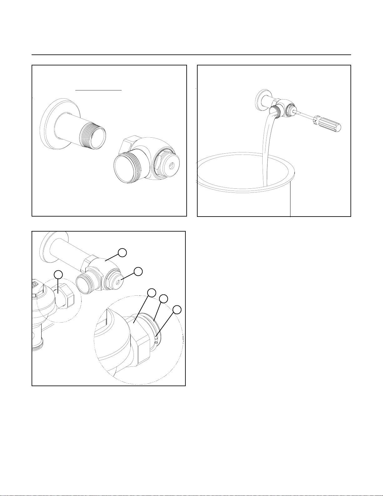
STEP 11 – Adjust Control Stop (Figure 6)
Adjust the control stop to meet the flow rate required for proper
cleaning of the fixture. Open control stop counterclockwise
one half turn from closed position. Activate Flushometer
simulating a user. Adjust the control stop after each flush
until the rate of flow delivered properly cleanses the fixture.
IMPORTANT NOTE: Excessive water flow creates noise,while
too little flow will not satisfy the needs of the fixture. Proper
adjustment is made when:
1. The plumbing fixture is cleansed after each flush without
splashing water out from the lip.
2. A quiet flushing cycle is achieved.
After adjustment: Replace the Zurn stop cap screw cover.
CAREANDCLEANINGINSTRUCTIONS
Do not use abrasive or chemical cleaners to clean
Flushometers and actuators as they may dull the luster and
attack the chrome or special decorative finishes. Use only
mild soap and water, then wipe dry with a clean cloth or towel.
While cleaning the bathroom tile, the Flushometer and
actuator should be protected from splattering of cleaner.Acids
and cleaning fluids can discolor or remove chrome plating.
Seasonal use.
Valves use in installations subject to shut down because of
cold and freezing conditions should be maintained in the fol-
lowing manner. After the main supply has been shut off and
the water drained from the system, remove the stop valve cap
and stop internals to allow the water to drain from the flush
valve and supply line.
SENSOR FEATURES (See Step 10 for instructions.)
1. Courtesy Flush: The Sensor will provide a courtesy flush
two seconds after a person is first detected. The courtesy
flush removes any residue from the fixture. The main flush
will occur when the user steps away from the fixture. The
courtesy flush can be manually activated/deactivated at
any time.
2. Automatic 8-Hour Flush: The sensor will provide an
automatic flush 8 hours after the last user. The automatic
flush can be manually activated/deactivated at any time.
3. Adjustable Range: The viewing distance is adjustable from
12" to 60".
A. Indicator Lights: The sensor unit has two operation lights,
red and green. The red light is lit when an object is
detected. The green is lit when the user leaves view of the
sensor and unit is flushing. The indicator lights can be
manually activated/deactivated at any time.
B. Function Light: Abnormal reflection detection function. If
an object is in the viewing range for more than 30 minutes
the red LED will blink. Range readjustment may be
required.
C. Maintenance Override (For Maintenance Purposes):
The sensor may be disabled for 10 minutes by placing a
magnet on the sensor lens for 3 to 5 seconds. After 10
minutes the sensor will automatically resume functioning.
Placing a magnet on the sensor for one second will restore
normal operation and also provide a flush. These features
are often desired for cleaning purposes.

FV38 Rev. D 2/27/12
Page 9
Care of Chrome plated surfaces.
The suggested cleaning of chrome plated surfaces is simply to clean them with soap and water then dry. Commercial cleaning compounds
are never recommended.
Seasonal use.
Valves usein installations subject to shut down because of cold and freezing conditions should be maintained in the following manner. After
the main supply has been shut off and the water drained from the systim, remove the stop valve cap and stop internals to allow the water to
drain from the flush valve and supply line.
ZURN INDUSTRIES, LLC.
♦♦
♦♦
♦
COMMERCIAL BRASS OPERATION
♦♦
♦♦
♦
5900 ELWIN BUCHANAN DRIVE
♦♦
♦♦
♦
SANFORD NC 27330
Phone: 1-800-997-3876
♦♦
♦♦
♦
Fax: 919-775-3541
♦♦
♦♦
♦
World Wide Web: www.zurn.com
In Canada: ZURN INDUSTRIES LIMITED
♦♦
♦♦
♦
3544 Nashua Drive
♦♦
♦♦
♦
Mississauga, Ontario L4V1L2
♦♦
♦♦
♦
Phone: 905-405-8272 Fax: 905-405-1292
Problem Possible Cause Corrective Action
1.) Stop valve is closed 1.) Open stop valve.
2.) Supplyvalve is closed. 2.) Open supplyvalve.
3) The electric wire(s) is not connected 3) Connect the wires.
4) The surface ofthe infrared cover is
stained. 4) Clean the surface ofthe sensor cover.
5) There is a reflective surface in front
of the sensor. 5) Remove the reflective surface from in front of the
sensor.
6) The detection range is notadjusted
properly. 6) Adjustthe detection range.
7) Actuator fault 7) Contactdistributor for replacement.
8) Sensor fault 8) Contactdistributor for replacement.
9) No power provided bypower supply 9) Replace power supply
No red LED with targetin view 1) The electric wire(s) is not connected
or sensor fault. 1) Connect the wires.
1) Electric wire fault. 1) Verifywire connections
2) Sensor fault 2) Replace sensor
1.) Stop valve is not open enough. 1.) Open stop valve for desired volume of water.
2.) Urinal diaphragm installed in closet
valve. 2.) Replace urinal diaphragm with proper closetpiston.
3.) Insufficientvolume or pressure at
supply. 3.) Consult fixture guide for minimum gallons per minute
flow and running pressure for satisfactoryperformance.
1.) Damaged diaphragm. 1.) Install new P6000-ECA,P6000-EUAreplacement kit.
2.) Enlarged by-pass orifice. 1.) Install new P6000-ECA,P6000-EUAreplacementkit.
1.) Enlarged by-pass orifice. 1.) Install new P6000-ECA,P6000-EUAreplacementkit.
2.) Urinal piston installed in closet 2.) Replace urinal piston with proper closet piston.
1.) Trip mechanism notseating
properlydue to foreign material
between trip mechanism and seat.
1.) Disassemble parts and rinse thoroughly.
2.) By-pass orifice is plugged or
partiallyplugged. 2.) Examine by-pass orifice and clean ifnecessarybeing
certain notto enlarge orifice opening.
3.) Line pressure is notadequate to
force trip mechanism to seal. 3.)Pressure is inadequate or has dropped below
minimum operating range. Steps should be taken to
increase the line pressure.
1.) Supplyvolume is more than is
necessary. 1.) Adjust downward on control stop.
2.) Lime accumulation on vortexor
spreader holes offixture. 2.)Remove the lime build up.
1.) Control stop maynotbe adjusted
for quietoperation. 1.) Adjust the control stop for quietoperation keeping in
mind the fixture evacuation requirements.
2.) Fixture maybe contributing to noise. 2.) Check noise created byfixture byplacing a cover over
the bowl opening to separate valve noise from bowl
noise. If itis determined the fixture is too noisy, consult
with fixture manufacturer.
3.)Piping system maybe source of
noise. 3.) High pressure in the system can sometimes be
controlled bythe stop valve. Other sources ofnoise may
be the absence of air chamber and shockarrestors,
loose pipes, impropersize pipes, etc. In these cases
the building engineershould be consulted.
Valve will not operate.
Flush is notconsidered quiet.
Watersplashes out offixture/
Valve is flushing too long ornot
shutting off.
Insufficient volume of water to
adequatelysiphon fixture
Valve is short flushing
Flush valve shuts off too quick.
Green LED illuminates with target
removed,butdoes notflush
Trouble Shooting

FV38 Rev. D 2/27/12
Page 10
ZEMS6000AV AquaVantage Valve
ZEMS6000
ZEMS6000-1
ZEMS6000-2
ZEMS6000-3
ZEMS6001
ZEMS6003
ZEMS6140 ZEMS6142 ZEMS6152
ZEMS6190 ZEMS6195 ZEMS6197
Install with
flange against
spud.
14A
13
12A
15A
15B
15C
15D 15D
15E
16A-C
16C
16A
16A17
18
15F 15G
15G
18
18
19
18
17A 17B
17A

FV38 Rev. D 2/27/12
Page 11
1. P6000-YBYC Cast Wall Escutcheon & Solder Kit
2A. P6000-D-SD Stop Assembly
2B. P6000-D-WH Stop Assembly for Wheel Handle
3. P6000-VC Vandal-Resistant Control Stop Cover
4. P6000-YBA Sweat Solder Adapter
5. P6000-LL-CP Valve Body Outside Cover
6. P6000-L Valve Body Inside Cover
7. P6000-ECA-WS Closet Repair Kit (3.5 gpf)
P6000-EUA-WS Urinal Repair Kit (1.5 gpf)
P6000-ECA-WS1 Low Consumption Closet Kit (1.6 gpf)
P6000-EUA-WS1 Low Consumption Urinal Kit (1.0 gpf)
P6000-ECA-HET High Efficiency Closet Kit (1.28 gpf)
8. Varies Valve Body
9. P6000-B Vacuum Breaker
10. PEMS6000-HYM ZEMS Actuator
11. PEMS6000-G ZEMS Escutcheon
12A. PESS6000-22 ZEMS Closet Sensor Plate
12B. PESS6000-22A ZEMSUrinal Sensor Plate
13. PESS6000-24 ZEMS Closet Override Button
14A. PEMS6000-26 ZEMS Closet Sensor
14B. PEMS6000-26A ZEMS Urinal Sensor
15A. P6000-A-AA-CP Chrome Plated 1-1/2” X 8 1/2” Vacuum
Breaker Assembly
P6000-2-A-AA-CP Chrome Plated 1-1/2” X 21” Vacuum
Breaker Assembly
P6000-3-A-AA-CP Chrome Plated 1-1/2” X 24” Vacuum
Breaker Assembly
15B. P6001-A-AA-CP Chrome Plated 1-1/4” X 8 1/2” Vacuum
20. P6000-K Tailpiece Coupling Assembly
21. P6000-C32 Locking Nut
22. P6000-C31 Tailpiece O-Ring
23. P6000-C30 SnapRing
24. Varies Tailpiece
25. Varies Adjustable Tailpiece Assembly
26. P6000-VC Cast Wall Escutcheon
27. P6000-YB-CVR Supply Cover Tube
Breaker Assembly
15C. P6003-A-AA-CP Chrome Plated 3/4” X 8 1/2” Vacuum
Breaker Assembly
15D. P6000-1-A-AA-RB Rough Brass 1-1/2” X 12 1/2” Vacuum
Breaker Assembly
15E. P6000-A-AA-RB Rough Brass 1-1/2” X 5” Vacuum
Breaker Assembly
15F. P6001-10-A-AA-RB Rough Brass 1-1/4” X 10” Vacuum
Breaker Assembly
15G. P6003-10-A-AA-RB Rough Brass 3/4” X 10” Vacuum
Breaker Assembly
16A. P6000-H 1 1/2” Spud Coupling Assembly
16B. P6001-H 1 1/4” Spud Coupling Assembly
16C. P6003-H 3/4” Spud Coupling Assembly
17A. P6000-QE3-RB Rough Brass 1 1/2” Slip Elbow
Assembly
17B. P6000-QE3-CP Chrome Plated 1 1/2” Slip Elbow
Assembly
18. Varies Chrome Plated slotless tube
19. Varies Rough Brass Slip Elbow
28. P6000-VC-SS Setscrew for Cast Wall Escutcheon
29. P6000-VC-W-VP 5/64 Allen Wrench
30. P6000-YB Sweat Solder Adapter
31. PESS6000-28 Yoke Screw
32. PESS6000-25 Yoke
33. PESS6000-23 Bracket
34. PESS6000-27 Bracket Screw
32
33
34
31

FV38 Rev. D 2/27/12
Page 12
ZURN INDUSTRIES, LLC.
♦♦
♦♦
♦
COMMERCIAL BRASS OPERATION
♦♦
♦♦
♦
5900 ELWIN BUCHANAN DRIVE
♦♦
♦♦
♦
SANFORD NC 27330
Phone: 1-800-997-3876
♦♦
♦♦
♦
Fax: 919-775-3541
♦♦
♦♦
♦
World Wide Web: www.zurn.com
In Canada: ZURN INDUSTRIES LIMITED
♦♦
♦♦
♦
3544 Nashua Drive
♦♦
♦♦
♦
Mississauga, Ontario L4V1L2
♦♦
♦♦
♦
Phone: 905-405-8272 Fax: 905-405-1292
Other manuals for AquaSense AV ZEMS Series
1
This manual suits for next models
11
Table of contents
Other ZURN Measuring Instrument manuals
Popular Measuring Instrument manuals by other brands

Primes
Primes BM+ 60 Original instructions

Riftek
Riftek IMR-L Series user manual

Nic
Nic PE-1 instruction manual

Anton Paar
Anton Paar EasyDens Instruction Manual and Safety Information

A.W. Sperry Instruments
A.W. Sperry Instruments DSA-1020 TRMS operating instructions

Meggitt
Meggitt Sensorex SX40000 instruction manual