manuals.online logo
Brands
  1. Home
  2. •
  3. Brands
  4. •
  5. 2gig Technologies
  6. •
  7. Security Sensor
  8. •
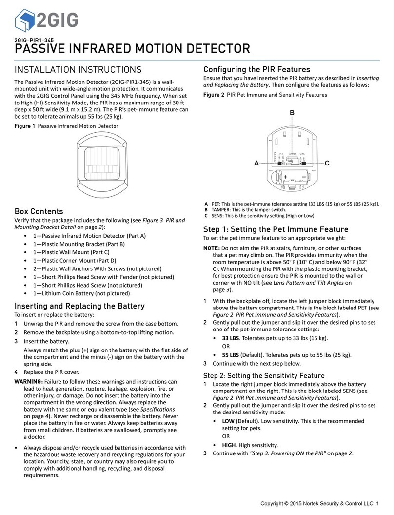
  9. 2gig Technologies 2GIG-FT1-345 User manual

2gig Technologies 2GIG-FT1-345 User manual

Copyright ©2015 Nortek Security & Control LLC 1
PRINTER’S INSTRUCTIONS:
INSTR,INSTL,2GIG-FT1 TEMP FLOOD SENSOR - P/N: 10008993 A- INK: BLACK - MATERIAL: 20 LB. MEAD BOND - SIZE: 8.5000” X 11.000” - TOL. +/- 0.125”- SCALE: 1-1 - PAGE 1 OF 2- FOLDING: FOLD 4X TO FINAL SIZE: 2.125" X 2.750"- FINISH WITH LOGO SHOWING
2GIG-FT1-345
FLOOD AND TEMPERATURE DETECTOR
INSTALLATION INSTRUCTIONS
The 2GIG-FT1-345 is a fully supervised, tamper protected one-way 345 MHz
sensor. It will monitor the ambient temperature and/or will detect a wet/dry flood
condion. The sensor reports wet/dry condions and temperature to the panel.
Flood Conditions
Once the sensor probe detects the presence of water for three (3) minutes, the
integral transmier will send a wet alarm transmission to the panel. The probe will
also send a restore (dry) report when the presence of liquid is no longer detected
by the flood probe for three (3) minutes. For flood reporng the sensor requires
the installaon of the supplied external flood probe. The sensor is capable of
detecng clean or dirty fresh water, salt water, or tap water.
Temperature Conditions
Heat:
1. If the temperature is more than 95° F (35°C) for five (5) minutes, the sensor
will send a loop 2 transmission.
2. If the temperature is less than 95°F (35°C) for five (5) minutes, the sensor will
send a loop 2 clear.
Cold:
1. If the temperature is less than 41°F (5°C) for five (5) minutes, the sensor will
send a loop 3 transmission.
2. In the temperature is more than 41°F (5°C) for five (5) minutes, the sensor
will send a loop 3 clear.
Contents
Verify that the package includes the following:
•1—2GIG Flood/Temperature Sensor
•1—Sensor Mounting Plate
•1—3V Lithium Battery ( Panasonic CR15H270 uninstalled)
•3—3/8” Phillips Screws
•1—Double Stick Tape Strip
•1—Probe Mounting Plate
Installation Tools Required
•Phillips Screwdriver
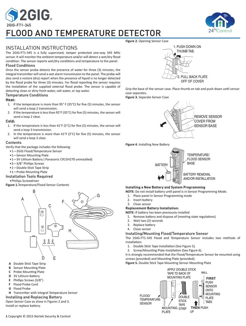
Figure 1.Temperature/Flood Sensor Contents
ADouble Sck Tape Strip
BSensor Mounng Plate
CProbe Mounng Plate
D3V Lithium Baery
EPhillips Screws (3/8”)
FFlood Probe Cord
GFlood Probe
HTransmier with Integral Temperature Sensor
Installing and Replacing Battery
Open Sensor Case as show in Figures 2 and 3.
Install or replace baery.
Figure 2. Opening Sensor Case
Grip the base of the sensor case. Place thumb on tab and push down unl sensor
case separates.
Figure 3. Separate Sensor Case
Figure 4. Installing New Baery
Installing a New Battery and System Programming
NOTE: Do not install baery unl panel is in Sensor Programming Mode.
1. Place panel in Sensor Programming mode
2. Insert baery
3. Close sensor
Replacement Battery Installation:
NOTE: If baery has been previously installed
1. Remove baery and dispose of (meeng state regulaons)
2. Wait two (2) seconds
3. Replace baery
4. Close sensor
Installing/Mounting Flood/Temperature Sensor
The 2GIG-FT1-345 Flood and Temperature Sensor includes two methods of
installaon:
1. Double Sck Tape Installaon (See Figure 5).
2. Screw/Mounng Plate Installaon (See Figure 6).
It is strongly recommended that the Flood/Temperature Sensor be mounted using
screws (provided) and Mounng Plate (provided).
Figure 5. Double Sck Tape Mounng Sensor Mounng Plate
A
B
C
DE
F
G
H
1. PUSH DOWN ON
THUMB TAB.
2. PULL BACK PLATE
OFF OF COVER
BATTERY REMOVAL
AND/OR INSTALLATION
BATTERY
TEMPERATURE/
FLOOD SENSOR
BASE
REMOVE SENSOR
COVER FROM
SENSOR BASE
MOUNTING
PLATE
DOUBLE
STICK
TAPE
STRIP
FLOOD/
TEMPERATURE
SENSOR
FIRST
PUSH
SENSOR
ONTO
MOUNTING
PLATE
TABS
THEN PUSH
UP
APPLY DOUBLE STICK
TAPE TO BACK OF
MOUNTING PLATE
WALL
2 Copyright © 2015 Nortek Security & Control
Figure 6. Screw Mounng Sensor Mounng Plate
Removing Flood/Temperature Sensor from Mounting Plate
If Flood/Temperature Sensor needs to be removed from the wall (for changing out
baery), open sensor case (See Figures 2 and 3). Remove baery, then Press Down
on release tab with flathead screwdriver and pull sensor UP.
Figure 7. Removing Sensor from Wall/Mounng Plate
Mounting Flood Probe
The Flood Probe must be mounted at floor level using the Probe Mounng Plate
and screw (included) mount as shown in Figure 8.
Figure 8. Mounng Probe Mounng Plate at Floor Line
Flood/Temperature Specifications
Operang Temperature: 32°to 120°F (0°to 49°C)
Operang Rel. Humidity: 5 to 95%, non-condensing
Operang Frequency: 345 MHz
Baery Type: CR2 3V lithium baery
Projected Baery Life: 5 Years
REGULATORY INFORMATION
This equipment has been tested and found to comply with the limits for Class B Digital
Device, pursuant to Part 15 of the FCC Rules. These limits are designed to provide reasonable
protecon against harmful interference in a residenal installaon. This equipment generates
and can radiate radio frequency energy and, if not installed and used in accordance with the
instrucons, may cause harmful interference to radio communicaons. However, there is
no guarantee that interference will not occur in a parcular installaon. If this equipment
does cause harmful interference to radio or television recepon, which can be determined by
turning the equipment offand on, the user is encouraged to try to correct the interference by
one or more of the following measures.
Reorient or relocate the receiving antenna
Increase the separaon between the equipment and receiver
Connect the equipment into an outlet on a circuit different from that to which the receiver
is connected
Consult the dealer or an experienced radio/TV technician for help.
Any changes or modificaons not expressly approved by the party responsible for compliance
could void the user’s authority to operate the equipment.
Le présent appareil est conforme aux CNR d’Industrie Canada applicables aux appareils
radio exempts de licence. Ľexploitaon est autorisée aux deux condions suivantes: (1)
ľappareil ne doit pas produire de brouillage, et (2) ľulisateur de ľappareil doit accepter tout
brouillage radioélectrique subi, même si le brouillage est suscepble ďen compromere le
fonconnement.
FCC COMPLIANCE STATEMENT
This device complies with FCC Rules and Regulaons as Part 15 devices as well as Industry
Canada license exempt RSS Rules and Regulaons. Operaon is subject to the following two
(2) condions: This device may not cause harmful interference. This device must accept any
interference received, including interference that may cause undesired operaon.
LIMITED WARRANTY
This Nortek Security & Control LLC product is warranted against defects in material and
workmanship for two (2) years. This warranty extends only to wholesale customers who
buy direct from Nortek Security & Control LLC or through Nortek Security & Control normal
distribuon channels. Nortek Security & Control does not warrant this product to consumers.
Consumers should inquire from their selling dealer as to the nature of the dealer’s warranty,
if any.
There are no obligaons or liabilies on the part of Nortek Security & Control for consequenal
damages arising out of or in connecon with use or performance of this product or other
indirect damages with respect to loss of property, revenue, or profit, or cost of removal,
installaon, or reinstallaon. All implied warranes for funconality, are valid only unl the
warranty expires. This Nortek Security &Control Warranty is in lieu of all other warranes
expressed or implied.
Nortek Security & Control LLC
1950 Camino Vida Roble, Suite 150
Carlsbad, CA 92008-6517 USA
For technical support in the USA and Canada:
855-2GIG-TECH (855-244-4832)
Email: 2gigtechsupport@nortek.com
Visit www.nortekcontrol.com for technical support hours of operaon
For technical support outside of the USA and Canada:
Visit dealer.2gig.com for a list of distributors in your region
10008993 A
SENSOR
MOUNTING
PLATE
FIRST
PUSH
SENSOR
ONTO
MOUNTING
PLATE
TABS
THEN PUSH
UP
MOUNT SENSOR
MOUNTING PLATE
WITH SCREWS (INCLUDED)
WALL
MOUNT FLOOD
PROBE MOUNTING
PLATE AT FLOOR LINE
FLOOD PROBE
SCREW FASTENER
INSTALL FLOOD
PROBE TO MOUNTING
PLATE UNTIL IT “SNAPS
”
INTO THE SIDE CLIP
SIDE CLIP
PRINTER’S INSTRUCTIONS:
INSTR,INSTL,2GIG-FT1 TEMP FLOOD SENSOR - P/N: 10008993 A- INK: BLACK - MATERIAL: 20 LB. MEAD BOND - SIZE: 8.5000” X 11.000” - TOL. +/- 0.125”- SCALE: 1-1 - PAGE 2 OF 2- FOLDING: FOLD 4X TO FINAL SIZE: 2.125" X 2.750"- FINISH WITH LOGO SHOWING
2GIG Flood & Temperature Control I Instrucon Manual
OPEN SENSOR
CASE AND REMOVE
BATTERY
PRESS DOWN ON
TAB IN UPPER LEFT
CORNER WITH FLATHEAD
SCREWDRIVER
THEN PUSH UP ON
SENSOR CASE TO REMOVE
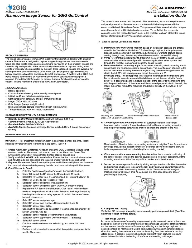
Other 2gig Technologies Security Sensor manuals

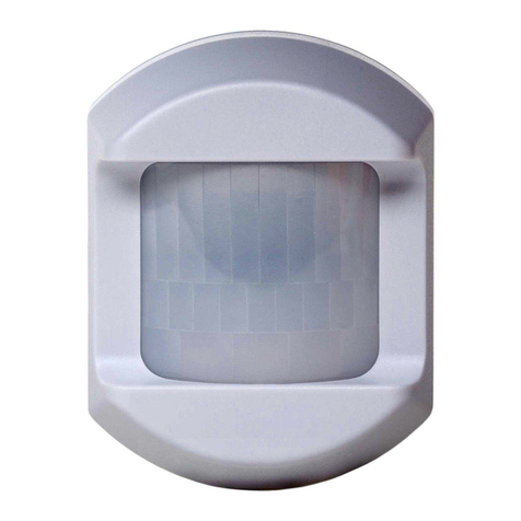
2gig Technologies pir1-345 User manual

2gig Technologies

2gig Technologies pir1-345 User manual

2gig Technologies 2GIG-FT6-345 User manual

2gig Technologies

2gig Technologies 2GIG-FT6-345 User manual

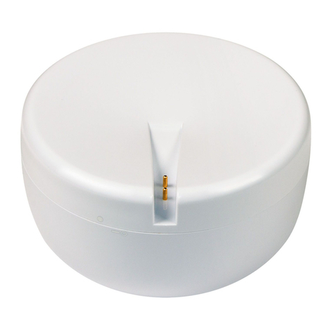
2gig Technologies 2GIG-FT1-345 User manual

2gig Technologies

2gig Technologies 2GIG-FT1-345 User manual

2gig Technologies Alarm.com ADC-IS-100-GC User manual

2gig Technologies

2gig Technologies Alarm.com ADC-IS-100-GC User manual

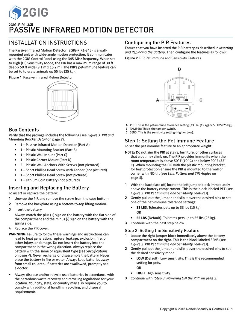
2gig Technologies 2GIG-PIR1-345 User manual

2gig Technologies

2gig Technologies 2GIG-PIR1-345 User manual

2gig Technologies 2GIG-PIR1E-345 User manual

2gig Technologies

2gig Technologies 2GIG-PIR1E-345 User manual

Popular Security Sensor manuals by other brands

HT HT20s user manual

HT

HT HT20s user manual

Velodyne HD HDL-64E S2 User's manual and programming guide

Velodyne

Velodyne HD HDL-64E S2 User's manual and programming guide

Feig Electronic VEK MNE2-R24-F operating instructions

Feig Electronic

Feig Electronic VEK MNE2-R24-F operating instructions

Basalte SENTIDO RS485 installation manual

Basalte

Basalte SENTIDO RS485 installation manual

Orno OR-CR-209 operating manual

Orno

Orno OR-CR-209 operating manual

Generex SM MD quick start guide

Generex

Generex SM MD quick start guide

BEA LZR-FLATSCAN W manual

BEA

BEA LZR-FLATSCAN W manual

Optex FLX-S-ST installation instructions

Optex

Optex FLX-S-ST installation instructions

Riken Keiki SD-D58-AC operating manual

Riken Keiki

Riken Keiki SD-D58-AC operating manual

System Sensor B401R Installation and maintenance instructions

System Sensor

System Sensor B401R Installation and maintenance instructions

Epson USN 52R operating manual

Epson

Epson USN 52R operating manual

C.P. Electronics MWS6-PRM-LV installation guide

C.P. Electronics

C.P. Electronics MWS6-PRM-LV installation guide

Techno Trade ALMAZ manual

Techno Trade

Techno Trade ALMAZ manual

Axio MET AX-T03 manual

Axio MET

Axio MET AX-T03 manual

Tecno Piu PTR 02/130 instruction manual

Tecno Piu

Tecno Piu PTR 02/130 instruction manual

Abus FUEM35000A quick guide

Abus

Abus FUEM35000A quick guide

wattstopper LMDW-101 quick start guide

wattstopper

wattstopper LMDW-101 quick start guide

HIK VISION DS-PDBG8-EG2-WE user manual

HIK VISION

HIK VISION DS-PDBG8-EG2-WE user manual

manuals.online logo
manuals.online logoBrands
  • About & Mission
  • Contact us
  • Privacy Policy
  • Terms and Conditions

Copyright 2025 Manuals.Online. All Rights Reserved.