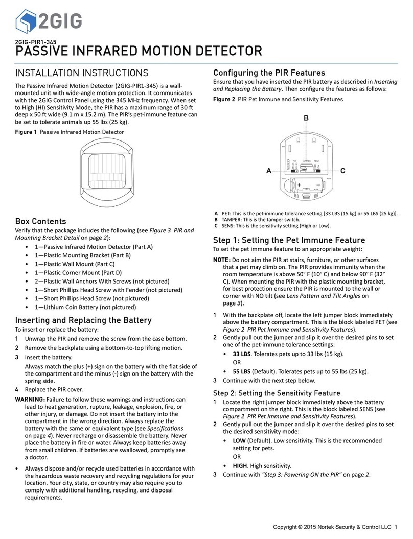
2gig Technologies pir1-345 User manual

Copyright © 2014 Linear LLC 1
2GIG-PIR1-345
PASSIVE INFRARED MOTION DETECTOR
INSTALLATION INSTRUCTIONS
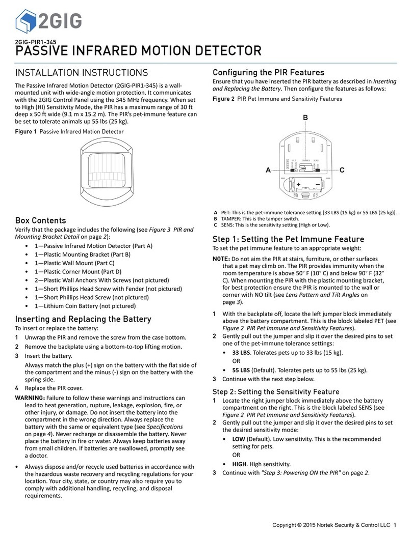
ThePassiveInfraredMotionDetector(2GIG‐PIR1‐345)isawall‐
mountedunitwithwide‐anglemotionprotection.Itcommunicates
withthe2GIGControlPanelusingthe345MHzfrequency.Whenset
toHigh(HI)SensitivityMode,thePIRhasamaximumrangeof30ft
deepx50ftwide(9.1mx15.2m).ThePIR’spet‐immunefeaturecan
besettotolerateanimalsup55lbs.
Figure 1 Passive Infrared Motion Detector
Box Contents
Verifythatthepackageincludesthefollowing(seeFigure3PIRand
MountingBracketDetailonpage2):
• 1—PassiveInfraredMotionDetector(PartA)
• 1—PlasticMountingBracket(PartB)
• 1—PlasticWallMount(PartC)
• 1—PlasticCornerMount(PartD)
• 2—PlasticWallAnchorsWithScrews(notpictured)
•1—ShortPhillipsHeadScrewwithFender(notpictured)
•1—ShortPhillipsHeadScrew(notpictured)
• 1—LithiumCoinBattery(notpictured)
Inserting and Replacing the Battery
Toinsertorreplacethebattery:
1UnwrapthePIRandremovethescrewfromthecasebottom.
2Removethebackplateusingabottom‐to‐topliftingmotion.
3Insertthebattery.
Alwaysmatchtheplus(+)signonthebatterywiththeflatsideof
thecompartmentandtheminus(‐)signonthebatterywiththe
springside.
4ReplacethePIRcover.
WARNING: Failuretofollowthesewarningsandinstructionscan
leadtoheatgeneration,rupture,leakage,explosion,fire,or
otherinjury,ordamage.Donotinsertthebatteryintothe
compartmentinthewrongdirection.Alwaysreplacethe
batterywiththesameorequivalenttype(seeSpecifications
onpage4).Neverrechargeordisassemblethebattery.Never
placethebatteryinfireorwater.Alwayskeepbatteriesaway
fromsmallchildren.Ifbatteriesareswallowed,promptlysee
adoctor.
•Alwaysdisposeand/orrecycleusedbatteriesinaccordancewith
thehazardouswasterecoveryandrecyclingregulationsforyour
location.Yourcity,state,orcountrymayalsorequireyouto
complywithadditionalhandling,recycling,anddisposal
requirements.
Configuring the PIR Features
EnsurethatyouhaveinsertedthePIRbatteryasdescribedinInserting
andReplacingtheBattery.Thenconfigurethefeaturesasfollows:
Figure 2 PIR Pet Immune and Sensitivity Features
Step 1: Setting the Pet Immune Feature
Tosetthepetimmunefeaturetoanappropriateweight:
NOTE: DonotaimthePIRatstairs,furniture,orothersurfaces
thatapetmayclimbon.ThePIRprovidesimmunitywhenthe
roomtemperatureisabove50°F(10°C)andbelow90°F(32°
C).WhenmountingthePIRwiththeplasticmountingbracket,
forbestprotectionensurethePIRismountedtothewallor
cornerwithNOtilt(seeLensPatternandTiltAngleson
page3).
1Withthebackplateoff,locatetheleftjumperblockimmediately
abovethebatterycompartment.ThisistheblocklabeledPET(see
Figure2PIRPetImmuneandSensitivityFeatures).
2Gentlypulloutthejumperandslipitoverthedesiredpinstoset
oneofthepet‐immunetolerancesettings:
•33LBS.Toleratespetsupto33lbs(15kg).
OR
•55LBS(Default).Toleratespetsupto55lbs(25kg).
3Continuewiththenextstepbelow.
Step 2: Setting the Sensitivity Feature
1Locatetherightjumperblockimmediatelyabovethebattery
compartmentontheright.ThisistheblocklabeledSENS(see
Figure2PIRPetImmuneandSensitivityFeatures).
2Gentlypulloutthejumperandslipitoverthedesiredpinstoset
thedesiredsensitivitymode:
•LOW(Default).Lowsensitivity.Thisistherecommended
settingforpets.
OR
•HIGH.Highsensitivity.
3ContinuewithStep3:PoweringONthePIRonpage2.
APET:Thisisthepet‐immunetolerancesetting(33LBSor55LBS).
BTAMPER:Thisisthetamperswitch.
CSENS:Thisisthesensitivitysetting(HighorLow).

2Copyright © 2014 Linear LLC
Passive Infrared Motion Detector | Installation Instructions
Step 3: Powering ON the PIR
Withthebatteryinserted(seeInsertingandReplacingtheBattery
onpage1),pressandreleasetheswitchlabeledTAMPER.Ittakes
approximately10secondsforthePIRtopowerON.
Mounting the PIR
TherearetwomethodsformountingthePIR:OptionA:Bracket
MountingorOptionB:Direct‐to‐WallMounting.Forbothmethods,
alwaysmountthePIRataheightof7.5ft(2.3m).
Figure 3 PIR and Mounting Bracket Detail
Option A: Bracket Mounting
SeeFigure3PIRandMountingBracketDetail.Ifyouplantomount
thePIRtoeitherthePlasticWallMountorPlasticCornerMount,
youmustfirstattachthePlasticMountingBrackettothePIR
backplate.
Step 1: Attaching the Plastic Mounting Bracket to the PIR
1RemovethePIRbackplate.
2InsertthetwostubsonthePlasticMountingBracketintothe
correspondingholesontheexteriorsideofthePIRbackplate.
3OntheinteriorofthePIRbackplate(seeFigure4PIR
Backplate—Direct‐to‐WallMountingGuides),usetheShort
PhillipsHeadScrew(provided)tosecurethePlasticMounting
Brackettothebackplate
4ReplacethePIRbackplate.
5Reattachthescrewthatwasremovedearliertothebottomof
thePIR.
6ContinuewitheitherStep2:WallMountingOptionorStep2:
CornerMountingOption.
NOTE: ForoptimumpetimmunitywhenusingthePlastic
MountingBracket,ensurethatthePIRismountedtothe
wallorcornerwithNOtilt(seeLensPatternandTiltAngles
onpage3).
Step 2: Wall Mounting Option
SeeFigure3PIRandMountingBracketDetail.IfusingthePlastic
WallMount(C),dothefollowing:
NOTE: EnsurethatyouhaveattachedthebrackettothePIR
backplate(seeStep1:AttachingthePlasticMounting
BrackettothePIR).
1Ontheintendedwall,usethetwo(2)PlasticWallAnchorsto
hangthePlasticWallMountataheightof7.5ft(2.3m).
2LocatethebarrelendofthePlasticMountingBracket.Locate
thebarrelendofthePlasticMountingBracketandcarefullyset
itontotheribbedpinofthePlasticWallMountatthedesired
angle(seeLensPatternandTiltAnglesonpage3).
3FromthetopsideofthePlasticWallMount,usetheShort
PhillipsHeadScrewwithFender(provided)tosecurethemount
tothebarrelendofthebracket.
Step 2: Corner Mounting Option
SeeFigure3PIRandMountingBracketDetail.IfusingPlastic
CornerMount,dothefollowing:
NOTE: EnsurethatyouhaveattachedthebrackettothePIR
backplate(seeStep1:AttachingthePlasticMounting
BrackettothePIRonpage2).
1Usethetwo(2)PlasticWallAnchorstohangthePlasticCorner
Mountataheightof7.5ft(2.3m).
2LocatethebarrelendofthePlasticMountingBracketand
carefullysetitontotheribbedpinofthePlasticWallMount.
Ensurethatyousetitatthedesiredangle(seeLensPatternand
TiltAnglesonpage3).
3FromthetopsideofthePlasticWallMount,usetheShort
PhillipsHeadScrewwithFender(provided)tosecurethemount
tothebarrelendofthebracket.
Option B: Direct-to-Wall Mounting
IfplanningtomountthePIRdirectlytoawall,usethebuilt‐in
mountingguidesoninteriorofthePIRbackplatetoscrewthe
backplateintothewall.
1RemovethePIRbackplate.
2Usethetwo(2)PlasticWallAnchorstoscrewthePIRbackplate
intothewallataheightof7.5ft(2.3m):
•Wall.Usethewallmountingguides(seeAbelow).
•CornerMount.Usetheleft‐orright‐cornermounting
guides(seeBbelow).
Figure 4 PIR Backplate—Direct-to-Wall Mounting Guides
APIR
BPlasticMountingBracket
CPlasticWallMount
DPlasticCornerMount
AWallMountingGuides(ForOptionB:Direct‐to‐WallMounting)
BCornerMountingGuides(ForOptionB:Direct‐to‐WallMounting)
CWallMountBracketGuide(ForOptionA:BracketMounting)

Passive Infrared Motion Detector | Installation Instructions
Copyright © 2014 Linear LLC 3
Environmental and Other Useful Information
WhilethePIRisahighlyreliableintrusiondetectiondevice,itdoes
notguaranteeagainstburglary.Anyintrusiondeviceissubjecttoa
“failuretowarn”foravarietyofreasons.Considerthefollowing
wheninstallingandsettingupthePIR:
1ThisPIRhasbuilt‐inprotectiontokeepbugsfromgettinginto
thesensorareaandcausingfalsealarms.Notethatthis
protectiondoesnotpreventinsectsfromcrawlingacrossthe
lensofthePIR,whichcouldtriggerthePIR.
2Infraredenergycanbereflectedoffanyglossysurfacessuchas
mirrors,windows,floors,orcountertopswithglossyfinish,and
slick‐finishedconcrete.Somesurfacesreflectlessthanothers
(e.g.thePIRcanseeachangeininfraredenergyoffofreflective
surfaceseveniftheheatorcoldsourceisnotwithinthePIR
detectionpattern).
3Windowsreflectinfraredenergy.Theyalsoallowsunlightor
lightfromothersources(e.g.,cars)topassthroughtothePIR.
ThePIRcandetectthesechangesininfraredenergy.For
example,ifsunlightpassingthroughawindowshinesontoa
hardwoodfloorandthechangeininfraredenergyisquick
enough,thePIRcantriggeranalarm.Thesameappliesifthe
PIRareaincludesawindow,eventhoughthepatternof
protectioncannot“see”throughglass.Lightsfromapassingcar
canalsopassthroughthewindowatnightandshinedirectly
intothePIR’slens.
4Heatingandairconditioningductsarealsoimportantbecauseif
theyblowairontoanobjectwithinthefieldofthePIR’sview,
thetemperatureofthatobjectcouldchangequicklyenoughfor
thePIRto“see”achangeininfraredenergy.PIR’scannotseeair
current,onlythechangeintemperatureofaphysicalobject.
5ThePIRsenseschangeintemperature.However,astheambient
temperatureoftheprotectedareaapproachesthetemperature
rangeof95°to120°F, thedetectionperformanceofthePIR
decreases.
6EnsurethattheareayouwishthePIRtocoverisfreeof
obstructions(forexample,curtains,screens,plants,andsoon.)
thatmayblockthepatternofcoverage.
7Anythingthatcanswayormoveduetoaircurrentcancausea
changeininfraredenergywithinthefieldsofview.Draftsfrom
doorsorwindowscancausethistohappen.Plants,balloons,
curtains,andhangingbasketsshouldneverbeleftinthePIR’s
fieldofview.
8DonotmountthePIRonasurfacethatallowsforanyvibration.
VibrationsnotonlycausethePIRtomovealittle,butitalso
causesthefieldsofviewinaroomtomovewithrespectthePIR.
AlittlevibrationcancausehavocwiththePIR’sfieldofview,
thusthePIRmayseeachangeinenergyandtriggerthealarm.
9AninstallationoftenrequiresthatthePIRisaimedatthedoor.
ThePIRmaydetectdoormovementbeforethedoorcontact
caninitiateanentrydelay,causingthealarmtotrigger.Ifyou
installthePIRfacingadoor,thenwhileprogrammingthePIR,
chooseanappropriatesensor/zonetype.
10 ThePIRONLYdetectsintrusionwithinthepatternofcoverage.
11 ThePIRdoesnotprovidevolumetricareaprotection.
12 ThePIRcreatesmultiplebeamsofprotection.Intrusioncanonly
bedetectedinunobstructedareascoveredbythosebeams.
13 ThePIRcannotdetectmotionorintrusionthatoccursbehind
walls,ceilings,floors,closeddoors,partitions,glassdoors,or
windows.
14 Tamperingwith,masking,painting,orsprayingofanymaterial
onthePIRlensoranypartoftheopticalsystemcanimpair
detectionability.
15 ThePIR,likeotherelectricaldevices,aresubjecttocomponent
failure.EventhoughthePIRisdesignedtolastaslongas10
years,theelectroniccomponentsaresubjecttofailure.
Lens Pattern and Tilt Angles
ThediagramsbelowshowthelenspatternandtiltanglesforthePIR
inmeters.
Figure 5 Lens Pattern—Top View
Figure 6 Tilt Angle—Side View
‐9° PIRtitleddownoneclick
0° PIRfacingtheoppositewall(Direct‐to‐wallormountingbracketwithno
tiltadjustment.
‐18° PIRtilteddowntwoclicks
+9° PIRtilteduponeclick

4Copyright © 2014 Linear LLC
Passive Infrared Motion Detector | Installation Instructions
SPECIFICATIONS
WirelessSignalRange 350ft(106.7m),openair,withWireless
ControlPanel
CodeOutputs Alarm,AlarmRestore,Tamper,Tamper
Restore,Supervisory,LowBattery
TransmitterFrequency 345.00MHz(crystalcontrolled)
UniqueIDCodes Overone(1)milliondifferentcode
combinations
SupervisoryInterval 70minutes
SensorType Quadelement
PetImmunitySelectable 33lb(15kg)or55lb(25kg;default)
SensitivityJumperSelectable HighorLow(default)
SuggestedMountingHeight 7.5ft(2.3m)
SensorRange 30ft(9.1m)x50ft(15.2m)
MaximumHorizontalSensingAngle 90°
Dimensions(LxWxH) 3.2x2.5x1.9in(8.12x6.35x4.82cm)
Weight(includingbattery&bracket) 3.7oz(104.9g)
HousingMaterial ABSPlastic
Color White
OperatingTemperature 32°‐120F°(0°‐49°C)
RelativeHumidity 5‐90%Non‐Condensing
Battery(installed) One(1)CR123A3Vorequivalent
Lithiumbattery
Certification Anatel,ETL,FCC,IC,IFETEL,andNOM
REGULATORY INFORMATION
FCC Notice
ThisdevicecomplieswithPart15oftheFCC'sRules.Operationis
subjecttothefollowingtwoconditions:
1Thisdevicemaynotcauseharmfulinterference,and
2Thisdevicemustacceptanyinterferencereceived,including
interferencethatmaycauseundesiredoperation.
Thisequipmenthasbeentestedandfoundtocomplywiththelimits
foraClassBdigitaldevice,pursuanttoPart15oftheFCCRules.
Theselimitsaredesignedtoprovidereasonableprotectionagainst
harmfulinterferenceinaresidentialinstallation.
Thisequipmentgenerates,usesandcanradiateradiofrequency
energyand,ifnotinstalledandusedinaccordancewiththe
instructions,maycauseharmfulinterferencetoradio
communications.However,thereisnoguaranteethatinterference
willnotoccurinaparticularinstallation.Ifthisequipmentdoes
causeharmfulinterferencetoradioortelevisionreception,which
canbedeterminedbyturningtheequipmentoffandon,theuseris
encouragedtotrytocorrecttheinterferencebyoneormoreofthe
followingmeasures:
•Reorientorrelocatethereceivingantenna.
•Increasetheseparationbetweentheequipmentand
receiver.
•Connecttheequipmentintoanoutletonacircuitdifferent
fromthattowhichthereceiverisconnected.
•Consultthedealeroranexperiencedradio/TVtechnicianfor
help.
ThisproductcomplieswithFCCradiationexposurelimitsforan
uncontrolledenvironment.Avoidoperatingthisproductata
distancelessthan20cmfromtheuser.
CAUTION: Anychangedormodificationsnotexpressly
approvedbythepartyresponsibleforcompliancecould
voidtheuser'sauthoritytooperatethisequipment.
Industry Canada (IC) Compliance
ThisdevicecomplieswithIndustryCanadalicense‐exemptRSS
standard(s).Operationissubjecttothefollowingtwoconditions:(1)
thisdevicemaynotcauseinterference,and(2)thisdevicemust
acceptanyinterference,includinginterferencethatmaycause
undesiredoperationofthedevice.
Repairstocertifiedequipmentshouldbemadebyanauthorized
Canadianmaintenancefacilitydesignatedbythesupplier.Any
repairsoralterationsmadebytheusertothisequipment,or
equipment
malfunctions,maygivethetelecommunicationscompanycauseto
requesttheusertodisconnecttheequipment.
Usersshouldensurefortheirownprotectionthattheelectrical
groundconnectionsofthepowerutility,telephonelinesand
internalmetallicwaterpipesystem,ifpresent,areconnected
together.Thisprecautionmaybeparticularlyimportantinrural
areas.
Usersshouldnotattempttomakesuchconnectionsthemselves,
butshouldcontacttheappropriateelectricinspectionauthority,or
electrician,asappropriate.
LIMITED WARRANTY
ThisLinearproductiswarrantedagainstdefectsinmaterialand
workmanshipfortwo(2)years.Thiswarrantyextendsonlyto
wholesalecustomerswhobuydirectfromLinearLLCorthrough
LinearLLC’snormaldistributionchannels.LinearLLCdoesnot
warrantthisproducttoconsumers.Consumersshouldinquirefrom
theirsellingdealerastothenatureofthedealer’swarranty,ifany.
TherearenoobligationsorliabilitiesonthepartofLinearLLCfor
consequentialdamagesarisingoutoforinconnectionwithuseor
performanceofthisproductorotherindirectdamageswithrespect
tolossofproperty,revenue,orprofit,orcostofremoval,
installation,orreinstallation.Allimpliedwarrantiesforfunctionality,
arevalidonlyuntilthewarrantyexpires.ThisLinearLLCWarrantyis
inlieuofallotherwarrantiesexpressedorimplied.
2GIGbyLinear
1950CaminoVidaRoble,Suite150
Carlsbad,CA92008USA
FortechnicalsupportintheUSAandCanada:
855‐2GIG‐TECH(855‐244‐4832)
Email:2gigtechsupport@linearcorp.com
Visitwebsitefortechnicalsupporthoursofoperation
FortechnicalsupportoutsideoftheUSAandCanada:
Contactyourregionaldistributor
Visitdealer.2gig.comforalistofdistributorsinyourregion
187‐0727Rev.G
Other 2gig Technologies Security Sensor manuals

2gig Technologies
2gig Technologies 2GIG-FT6-345 User manual

2gig Technologies
2gig Technologies 2GIG-FT1-345 User manual

2gig Technologies
2gig Technologies 2GIG-PIR1E-345 User manual

2gig Technologies
2gig Technologies 2GIG-PIR1-345 User manual

2gig Technologies
2gig Technologies 2GIG-FT1-345 User manual

2gig Technologies
2gig Technologies Alarm.com ADC-IS-100-GC User manual
Popular Security Sensor manuals by other brands

Thermo Scientific
Thermo Scientific Accela PDA Hardware manual

PCB Piezotronics
PCB Piezotronics ICP T356A32 Installation and operating manual

Bosch
Bosch RADION Life Safety installation manual

PCB
PCB Load & Torque 4115K-13A Installation and operating manual

jablotron
jablotron JA-150P PET manual

Comelit
Comelit DT12EAM manual