2PrintBeta Beta Prusa Standard User manual

Assembly Instructions Beta Prusa Standard & Deluxe 01/07/14
Assembly Instructions
Beta Prusa Standard & Deluxe
3D Printer
Version 2 6
Date 01/07/14
Page 1 / 67

Assembly Instructions Beta Prusa Standard & Deluxe 01/07/14
General data about the assembly instructions for an incomplete machine
according to appendix VI of the G machinery directive 2006/42/ G
Manufacturer:
Wenger & Krautwasser GbR - 2PrintBeta
Scheffelstrasse 8
78462 Konstanz
Description of the machine:
Identification: Beta Prusa 3D printer
Type: Standard with linear bearings
Year: 2012
Conditions that must be met for the incomplete machine so that it can properly, and
without compromising the safety and health of peoples, be assembled with other
parts to form a complete machine:
Condition 1: Let an expert check the electrical connections of the machine
Information over the undersigned:
Name: Dominik Wenger
Function: Shareholder Wenger & Krautwasser GbR
01 11 2012
_________________________________________
Date, Signature
This work is licensed under a Creative Commons Attribution-NonCommercial 3 0 Germany License
Page 2/ 67

Assembly Instructions Beta Prusa Standard & Deluxe 01/07/14
Congratulations on purchasing a Beta Prusa 3D Printer!
Please read the following assembly instructions carefully and keep the document on a safe
place Please follow carefully all instructions and lookout for the warning symbols
Table of Contents
SAFETY INSTRUCTIONS....................................................................................................................................4
ASSEMBLY OF THE FRAME..............................................................................................................................5
STEP 1 1
6
STEP 1 2
7
STEP 1 3
9
STEP 1 4
10
STEP 1 5
11
STEP 1 6
12
STEP 1 7
13
STEP 1 8
14
STEP 1 9
17
ASSEMBLY OF THE AXES................................................................................................................................18
STEP 2 1
19
STEP 2 2
21
STEP 2 3
24
STEP 2 4
26
STEP 2 5
28
STEP 2 6
30
STEP 2 7
32
ASSEMBLY OF THE EXTRUDER....................................................................................................................35
STEP 3 1
36
STEP 3 2
38
STEP 3 3
39
STEP 3 4
41
ASSEMBLY OF THE PRINT BED AND EXTRAS..........................................................................................42
STEP 4 1
43
STEP 4 2
44
STEP 4 3
45
STEP 4 4
46
ASSEMBLY OF THE ELECTRONICS..............................................................................................................49
STEP 5 1
50
STEP 5 2
53
STEP 5 3
55
STEP 5 4
66
Page 3/ 67
Assembly Instructions Beta Prusa Standard & Deluxe 01/07/14
Safety Instructions
Only assemble a Beta Prusa 3D printer according to the assembly instructions written here
Please take notice of the following Symbols and Notices They are structured into danger
levels according to ISO 3864-2
DANG R
Refers to an imminent Danger.
If the information is not followed, it can result in death or serious injury
(invalidity).
Indicates a possible dangerous situation.
If the information is not followed, it can result in death or serious injury
(invalidity).
ATT NTION
Indicates a potentially dangerous situation.
If the information is not followed, damage to property or light to
medium personal injuries are possible.
NOTIC
Indicates general notes, useful operator tips and operating
recommendations which do not affect the safety and health of
personnel.
Page 4/ 67
WARNING

Assembly Instructions Beta Prusa Standard & Deluxe 01/07/14
Chapter I
Assembly of the Frame
Page 5 / 67

Assembly Instructions Beta Prusa Standard & Deluxe 01/07/14
Step 1.1
Needed parts for step 1.1
The following parts are needed for this step:
2x Frame vertex with foot
1x Bar clamp
6x Washer M8
6x Nut M8
1x Threaded rod M8 x 370 mm
Assembly Step 1.1
Assemble the bar clamp between two frame vertices like its shown in the picture above
Don't completely fasten the nuts yet
Page 6/ 67

Assembly Instructions Beta Prusa Standard & Deluxe 01/07/14
Step 1.2
Needed parts for step 1.2
The following parts are needed for this step:
1x Pre-assembled part from step 1 1
1x Frame vertex without foot
8x Washer M8
8x Nut M8
2x Threaded rod M8 x 370 mm
Assembly Step 1.2
Page 7/ 67
Assembly Instructions Beta Prusa Standard & Deluxe 01/07/14
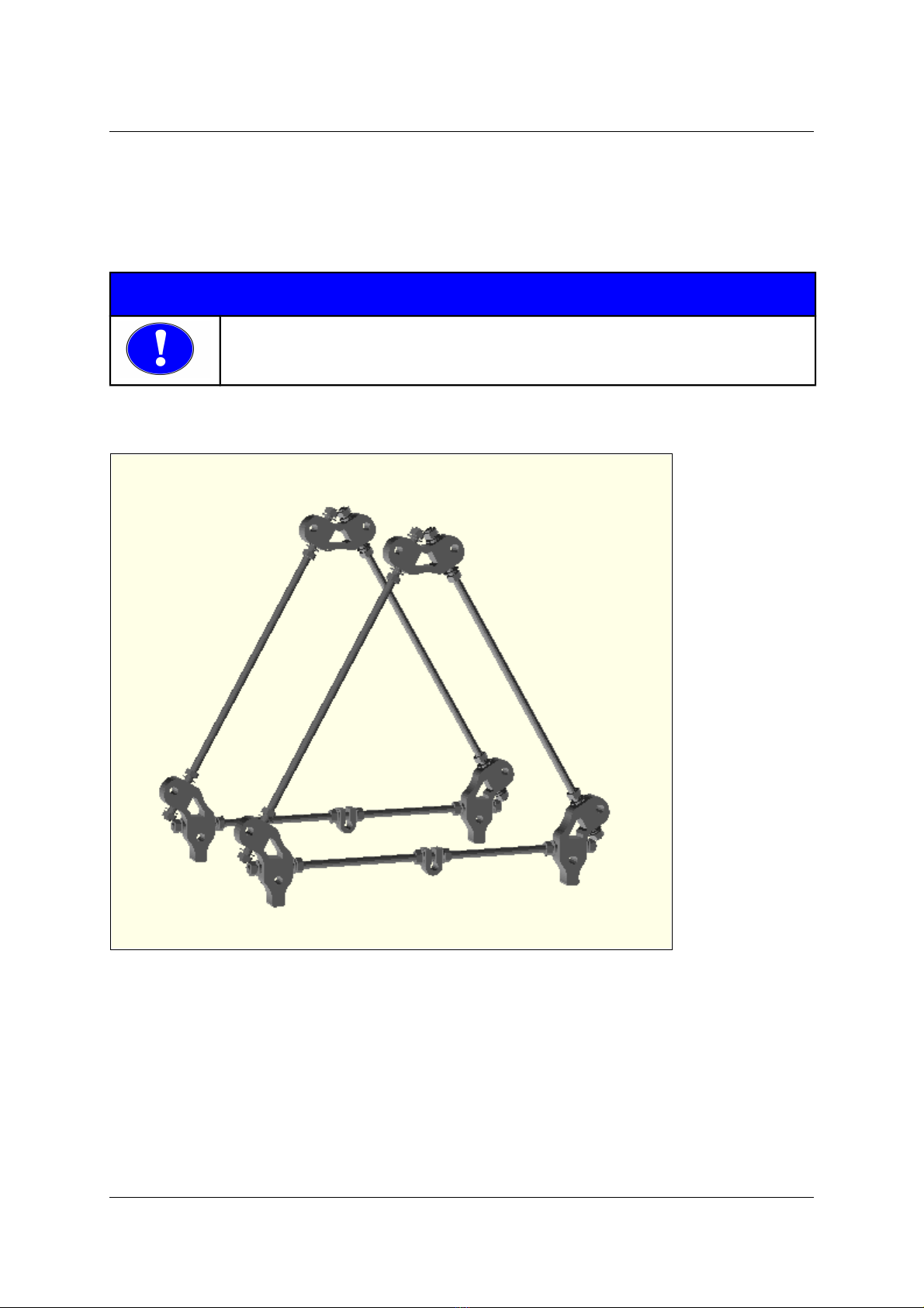
Connect the part from step 1 1 with the frame vertex and the rods to a triangle
Make sure that all sides of the triangle are exactly the same length The distance between
the outer edges of the plastic parts should be 291 mm
Repeat the previous two steps and build a second triangle
NOTIC
Make sure all sides of both triangles are exactly the same length.
Now fasten all nuts on the frame vertices
Assembly of step 1.2 repeated
Page 8/ 67

Assembly Instructions Beta Prusa Standard & Deluxe 01/07/14
Step 1.3
Needed parts for step 1.3
The following parts are needed for this step:
4x Washer M8
4x Nut M8
1x Threaded rod M8 x 294 mm
Assembly Step 1.3
Position the nuts and washer on the threaded rod as shown in the picture above
Page 9/ 67

Assembly Instructions Beta Prusa Standard & Deluxe 01/07/14
Step 1.4
Needed parts for step 1.4
The following parts are needed for this step:
1x Belt guide
2x Bar clamp
10x Washer M8
2x Big Washer M8
8x Nut M8
1x Bearing 608ZZ
1x Threaded rod M8 x 294 mm
Bearing 608zz in belt guide
Press the 608ZZ bearing into the belt guide until it's in the middle of the guide
Assembly step 1.4
Position the parts on the threaded rod as shown in the picture above
Page 10/ 67
Other manuals for Beta Prusa Standard
1
This manual suits for next models
1
Table of contents
Other 2PrintBeta 3D Printer manuals


