10 PP
2VV. Creating innovative solutions for you and your business since 1995.
ver.1 20-08-21
HW Settings
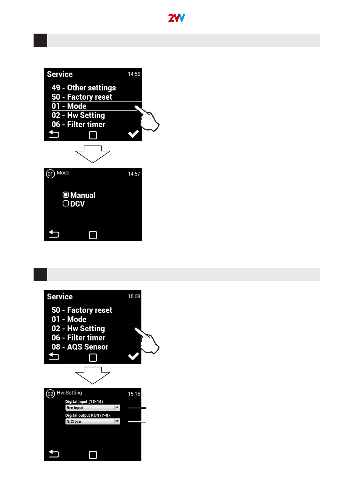
Mode
Select required ventilation mode
DCV - Ventilation according to the requirements of the air
quality sensor (AQS)
• Unit ventilates at the air quality sensor (AQS) require-
ments, e.g. CO2, RH (sensor control signal must range
from 0-10V).
Manual - manual ventilation mode
• Unit ventilates at the selected power independent of the
AQS
The Software reset (menu 48) must be performed to save
the changes
• This menu sets the logic used by input 15-16 and RUN
output.
• Input (15-16) – Lets you choose to control the unit with the
movement sensor or as a re contact. In case of re, the
behavior of the unit can be set (settings in service menu no.
13).
• Output (7-8) – Lets you set the logic of the RUN contact
switch as follows: N.close (normally closed) or N.Open
(normally open)
02
01
1
2
1. Option to select function of switching motion sensor or
re contact
2. Possibility to choose the logic of the run contact (N.Clo-
se / N.Open)