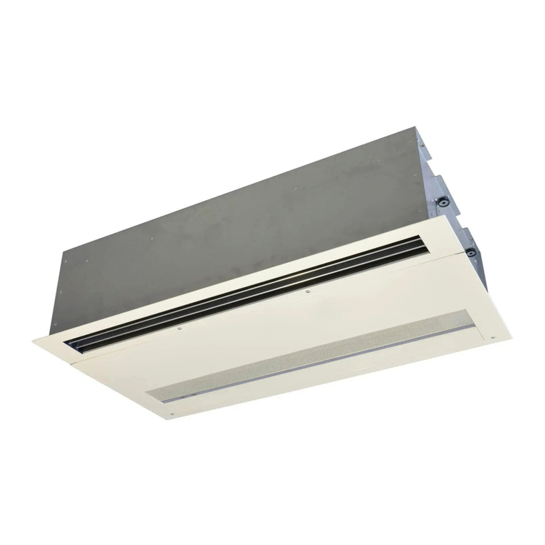
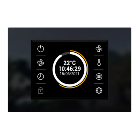
2VV SC-C-AC5-04 User manual

MANUAL
INSTALLATION AND OPERATION
SC-C/S
EN

23
2 VV. Creating innovative solutions for you and your business since 1995.
1. BEFORE YOU BEGIN
The following symbols in the manual serve for better guidance. The following table describes the symbols and their meaning.
Before you begin the installation, thoroughly read the manual to safely and properly using this product.
Symbol Meaning
CAUTION!
DO NOT SKIP!
YOU WILL NEED
TECHNICAL INFORMATION
Warning or Caution
Important instructions
Practical tips and information
Reference to a dierent part of the
manual
Detailed technical information
This manual provides instructions on how to properly install the unit. Before installing the unit, carefully read the entire manual.
The manufacturer reserves the right to make changes, including in the technical documentation, without prior notice. Keep the
manual in a safe place for future reference. The manual is an integral part of the product.
Declaration of conformity
The product has been designed, produced an marketed in compliance with all the applicable provisions, and abides to the pro-
visions of the European Parliament and Council, including the amendments under which it has been classied. It is safe under
normal conditions and under the conditions laid down by the manual. The assessment was conducted pursuant to harmonized
European standards included in the relevant EC Declaration of Conformity. The current and full version of the EC Declaration of
Conformity can be found at www.2vv.cz

23
2 VV. Creating innovative solutions for you and your business since 1995.
DO NOT SKIP!
• If the unit was shipped at temperatures below 0°C, let it
rest for at least 2 hours without turning it on, so that its
interior temperature can match the surroundings.
2. UNPACKING
2.1 INSPECT THE DELIVERY
DO NOT SKIP!
• Unpack the product upon delivery and control for dam-
ages. In case of damage, inform and le a report with the
carrier.
• Any claims that have not been led in due time, will be
disregarded later.
• Check that you have received the model ordered. Should
the delivered model dier from the one ordered, do not
unpack the unit and notify the supplier immediately.
• After unpacking the product, check that the unit and the
accessories are in good order. Contact the supplier in case
of any doubt.
• Do not attempt to commission a damaged unit.
• In the event that you decide not to unpack the unit imme-
diately after delivery, it must be stored in a dry place with
temperatures ranging from +5 °C to +40 °C.
• This product must not be used by persons (incl. minors)
with mental or physical disabilities, or insucient experi-
ence or knowledge in the safe use thereof, unless they are
supervised or instructed on how to use the product by a
person responsible for their safety.
• Do no let children play with the unit.
+5 oC
+40 oC
All the packing material is environmentally
friendly and can be reused or recycled. Please,
contribute actively to the protection of the
environment and procure the regular disposal
or recycling of packing materials.
SC-C-ACx
SC-S-ACx
SC-C-EC
SC-S-EC
1X
1X
1X
1X
4X
4X
1X
1X
1X
1X
4X
2X1X
1X
1X
14X
14X
4X
2X
1X

45
2 VV. Creating innovative solutions for you and your business since 1995.
3. MAIN SECTION
SC-x-ACx
SC-x-EC
1
2
3
4
8
6
7
5
1
2
1Regulator lid
2Cable housing
3Connecting distributor plate
4Source
5AC module
6Grounding bridge (PE)
7Null bridge (N)
8Controlling electronics
4
3
8

45
2 VV. Creating innovative solutions for you and your business since 1995.
SC-x-EC regulation box
4. DIMENSIONS
x
* - Dimensions for installing regulation on wall
SC-x-ACx regulation box
* *
**
*
*
239,7
87,4 260,5
239,9
210
230
B
F
E
A
C
D
A3
8
5
7
6
2
4
3
1
C
E
D
F
A
B
4
1
3
6
8
5
2
7
DATUM:
ISO 8015
ISO 1302 Ra
R
DRSNOST:
SCHVÁLIL:
ČÍSLO MATERIÁLU:
VERZE
2VV s.r.o., Poděbradská 289
CZ-530 09 PARDUBICE
002
NÁZEV
ČÍSLO
2-602-S06285
PROMÍTÁNÍ
KRESLIL:
MĚŘÍTKO
1:2
HMOTNOST ČISTÁ:
TOLEROVÁNÍ:
PŘESNOST:
DATUM:
DŮVOD ZMĚNY:
NÁZEV MATERIÁLU:
David Špráchal
16.3.2016
Josef Řezníček A
14.3.2016
ISO 2768 - mK
OE-M-AC5
-
3.68 kg
*
*

67
2 VV. Creating innovative solutions for you and your business since 1995.
5. TECHNICAL PARAMETERS
6. INSTALLATION
6.1 SELECT INSTALLATION SITE
The assembly and above all the connection of the control unit may only be carried out by a trained person with the
appropriate permit for connecting electrical devices who has suitable tools and resources available. During assembly it
is necessary to uphold all instructions and recommendations stated in this manual.
TECHNICAL INFORMATION
The regulator must be operated in places corresponding to the given coverage according to the IP.
6.2 ASSEMBLY TO WORKING POSITION
The regulator is to e installed on a wall in a vertical position.
The regulator must be installed in such a way that air may ow around it and that it may not overheat.
Maintain the minimal recommended clearance distance.
The regulator must be installed in such a way as to ensure sucient access in the event of maintenance, servicing, or disassembly.
The regulator is xed to the wall using screws and anchors or bolts.
No ammable materials may be kept within 100 mm of the regulator.
01/10 str.02
M-04.0102-01
2.5 KONTROLA
DODÁVKY
Po dodání ihned zkontrolujte zda není jednotka ani
ovladač poškozen. V případě poškození jednotku dále
nerozbalujte a závadu nahlaste dodavateli. V případě
poškození obalu přizvěte dopravce. Zkontrolujte zda
souhlasí Vámi objednaný typ jednotky s dodaným. Typový
štítek je umístěn na boku skříně regulátoru. Dálkový
ovladač s 5m komunikačním kabelem je umístěn v
jednotce.
Součástí dodávky řídicí jednotky jsou:
o regulátor
o dálkový ovladač s kabelem
o návod
Nebude-li reklamace uplatněna včas, nelze případné
nároky uplatnit v budoucnosti.
2.6 VYBALENÍ Vyjměte regulátor z obalu a pootočením šroubů ji otevřete.
Uvnitř naleznete dálkový ovladač a návod k použití, který uschovejte.
Všechny použité obalové materiály jsou ekologické a lze je znovu použít nebo recyklovat.
Přispějte aktivně k ochraně životního prostředí a dbejte na správnou likvidaci a znovu zhodnocení obalových materiálů.
3 INSTALACE
Montáž a hlavně zapojení řídicí jednotky může provést pouze proškolená osoba s příslušným oprávněním pro
zapojování elektrických zařízení, která má k dispozici vhodné nářadí a prostředky. Při montáži je nutné
dodržovat veškeré pokyny a doporučení uvedené v tomto návodu.
3.1 MONTÁŽ DO
PRACOVNÍ POLOHY
Regulátor a ovladač se instaluje na stěnu nebo přímo na
ovládané zařízení ve svislé nebo vodorovné poloze.
Regulátor musí být instalován tak, aby mohl okolo proudit
vzduch a nedocházelo k jeho přehřívání.
Dodržujte minimální doporučené odstupové vzdálenosti.
Regulátor i dálkový ovladač musejí být instalovány tak,
aby k nim byl dostatečný přístup v případě údržby, servisu
nebo demontáže.
Regulátor a dálkový ovladač se připevňují pomocí vrutů a
hmoždinek na zeď a nebo pomocí šroubů přímo na plášť
clony.
Do vzdálenosti 100 mm od regulátoru jednotky se nesmí
nacházet žádné hořlavé hmoty.
Minimální vzdálenost od stavební konstrukce
min.
100 mm
min.
100 mm
3.2 PŘIPOJENÍ
ELEKTROINSTALACE
Regulátor a dálkový ovladač musejí být vždy před jakýmkoliv zásahem odpojeny od hlavního přívodu el. energie.
Při zapojení řídicí jednotky musí být dodrženy pokyny uvedené v tomto návodu a příslušné národní předpisy a směrnice.
Všechny fáze elektrického přívodu do regulátoru musí být připojeny přes ochranný výkonový jistič odpovídajícího
proudu a typu.
Vzdálenost mezi rozpojenými kontakty musí být větší než 3 mm.
Jmenovité hodnoty elektrických parametrů jednotky jsou uvedeny na výrobním štítku.
Dálkový ovladač se připojí k regulátoru pomocí přiloženého komunikačního kabelu.
Hlavní přívod el. energie, spínané prvky a příslušenství se připojí dle schéma zapojení.
Pokud není regulátor dostatečně dimenzován pro ovládané zařízení, je možné zařízení ovládat pomocí většího
množství regulátorů propojených datovým kabelem řetězení.
Řetězení lze použít např. pro připojení přívodního a odvodního ventilátoru.
Při řetězení však nelze připojit jeden ventilátor na dvě řídicí jednotky!
Připojené ventilátory nesmí překročit jmenovitou hodnotu proudu řídicí jednotky!
Jakékoliv zásahy a změny ve vnitřním zapojení řídicí jednotky nejsou povoleny a vedou ke ztrátě záruky.
Regulátor je vybaven tavnou pojistkou, která je přístupná po odmontování víka skříně regulátoru.
V případě požáru je nutné zařízení hasit práškovým nebo CO2 hasícím přístrojem.
min.
500 mm
Type Voltage [V/Hz] Maximum current
AC fans [A] Electric sheathing [IP] Weight [kg] Maximum number of connectible
EC fans [units]
SC-C-AC5-04
230 / 50~60 4 65 13.5 ---
SC-C-AC5-07
230 / 50~60 7 65 15 ---
SC-C-AC5-16
230 / 50~60 16 65 23 ---
SC-S-AC5-04
230 / 50~60 4 65 13.5 ---
SC-S-AC5-07
230 / 50~60 7 65 15 ---
SC-S-AC5-16
230 / 50~60 16 65 23 ---
SC-C-EC
115~230 / 50~60 --- 40 3 10
SC-S-EC
115~230 / 50~60 --- 40 3 5

67
TECHNICAL INFORMATION
For installation of the AC version of the regulator onto the wall, we recommend separating the internal section (electronics and trans-
former) from the regulator box for easier handling.
1. 2.
6.3. INSTALLATION AND ASSEMBLY OF ELECTRONICS
CAUTION!
• The regulator must always be disconnected from the main power supply prior to opening the unit.
• The installation can be carried out only by a professional with qualications in electronics.
• The manual must be followed, along with the laws and regulations applicable in the given country.
• The unit must be connected to the main power source with an insulated cable with heat resistance compliant with the diameter and
applicable laws and regulations of the given country.
• All phases of the electrical intake to the regulator must be connected via a protective power breaker corresponding to the current and
model.
• The distance between disconnected contacts must be greater than 3 mm.
• The nominal values of the electrical parameters of the unit are listed on the manufacturer’s label.
• The main intake of electrical power, switching elements, accessories should be connected according to the connection schematic.
• The connected fans may not exceed the nominal value of current of the control unit!
• Opening and modifying the internal connection of the control unit is prohibited and can void the warranty.
• In case of re, it is necessary to extinguish the device with power or CO2 re extinguisher.
• The unit must be connected in such a way that it can be disconnected from the power supply with one piece.
Recommended breakers:
Table of minimum sizes of breakers according to the regulator model.
The suitability of the breaker always depends on the specic conditions at the site of installation. The following table is for orientation purposes only!!!
AC-C
SC-C-AC5-04
6A
SC-C-AC5-07
10A
SC-C-AC5-16
20A
AC-S
SC-S-AC5-04
6A
SC-S-AC5-07
10A
SC-S-AC5-16
20A
EC
SC-C-EC
16A
SC-S-EC
16A
• To mount the regulator, use the corresponding anchors and
screws.
• To preserve the IP cover of the box, use screws and washers
provided
• Drill
• 4x screws
• 4x anchors
• 4x washers with sealing rings (included)
The regulator must be installed as shown in the pictures, i.e. with
bushing downward.
Activating remote control
1. 2. 3. 4.
5. 6.
CANL (30)
CANH (29)
+12 V (27)
GND (28)

89
2 VV. Creating innovative solutions for you and your business since 1995.
MASTER UNIT
6. INSTALLATION6. INSTALLATION
2
1
7 8 9 10
Run Error
contact
11 12
Water
pump
13 14
Night/Day
17 18
External
control
23
63
25
A
A
B
B
GND
GND 66
66
24
64
26
20
20
0-10V
L-in
L-in
L-out
L-out
63
CANH
A
CANL
GND
+12 V
B
A
B
+12 V
GND
6465 66
2
ON
ON
SLAVE
MODBUS
RTU
Flap-
Mixing
Chamber
+
GND
LL-Fan Heat-1 Heat-2 N
+24
GND
1
SC-C-AC
Heat
+
0-10V

89
2 VV. Creating innovative solutions for you and your business since 1995.
SLAVE UNIT
6. INSTALLATION6. INSTALLATION
SC-S-AC
9
24 23 22
1110 8
3 4
External
control
2
1
2
1
A
B
B
A
GND
GND
Slave unit
MASTER
LL-Fan Heat-1 Heat-2 N
+24
GND
Heat
+
0-10V

10 11
2 VV. Creating innovative solutions for you and your business since 1995.
6. INSTALLATION6. INSTALLATION
L
7 8
Run
11 12
Water
pump
17 18
External
control
L-in
L-out
4131 4232
EC FAN - MAX 5 EC FAN - MAX 5
PWM 10V
PWM 10V
GND
GND
L
N N
GND
GND
TACHO/RPM - MOTOR 1
TACHO/RPM - MOTOR 2
TACHO/RPM - MOTOR 3
TACHO/RPM - MOTOR 4
TACHO/RPM - MOTOR 5
TACHO/RPM - MOTOR 6
TACHO/RPM - MOTOR 7
TACHO/RPM - MOTOR 8
TACHO/RPM - MOTOR 9
TACHO/RPM - MOTOR 10
63
CANH
A
CANL
GND
+12 V
B
A
B
+12 V
GND
6465 66
SC-C-EC
1
2
3
ON
ON
9 10
Error
contact
L-in
L-out
+24+
63
A B GND
66
64 20
SLAVE
25
A B GND
66
26 20
MODBUS
RTU
13 14
Night/Day
23 24
0-10V
Flap-
Mixing
Chamber
+
GND
1
2
3
GND 0-10V
Heat
LL
N N
+24+GND 0-10V
Heat

10 11
2 VV. Creating innovative solutions for you and your business since 1995.
6. INSTALLATION6. INSTALLATION
17 18
External
control
31 32
EC FAN
SLAVE
UNIT
22
9
23
10
24
11
Master UNIT
PWM 10V
GND
GND
GND
TACHO/RPM - MOTOR 1
TACHO/RPM - MOTOR 2
TACHO/RPM - MOTOR 3
TACHO/RPM - MOTOR 4
TACHO/RPM - MOTOR 5
TACHO/RPM - MOTOR 6
TACHO/RPM - MOTOR 7
TACHO/RPM - MOTOR 8
TACHO/RPM - MOTOR 9
TACHO/RPM - MOTOR 10
1
2
3
1
2
3
GND
GND
A
B
B
A
SC-S-EC
Max 5 motors!!!
When designing the wiring for the drive power of the EC engines, it is
necessary to take into consideration any possible decrease in power!!!
e minimum power for the lowest engine performance is 1.5V!!!
LL
N N
+24+GND 0-10V
Heat

12 13
2 VV. Creating innovative solutions for you and your business since 1995.
Max 150m
MASTER SLAVE no.1
The total length of the bus of all chained shutters may not exceed a length of 150m!!!
6. ELECTRONIC SCHEMATICS CHAINING
SLAVE no.2 SLAVE no.10
SLAVESLAVE
MASTER
A
A
A
A
A
B
B
B
B
B
GND
GND
GND
GND
GND
SLAVE
no.1
no.2
no. 3
no. 4
no. 5
SLAVE
no. 6
no. 7
no. 8
no. 9
no. 10 A
SLAVE

12 13
2 VV. Creating innovative solutions for you and your business since 1995.
READ CAREFULLY!
Before deploying into operation, check the following:
• that the device is properly xed on a load-bearing structure
• that the device has been properly closed
• that the electrical power has been properly connected, including grounding and protection of exterior starters.
• that all elements of electrical parts have been properly connected
• that the installation corresponds to all instructions given in this manual
• that no tool or other object that can damage the device has remained in it
CAUTION!
• Opening and modifying the internal connection of the control unit is prohibited and can void the warranty.
• We recommend using the accessories we provide. Contact your supplier in case of doubts with the use of non-original accesso-
ries.
DEPLOYMENT
After activating the main power supply, the display of the controller lights up and servicing data is downloaded.
The device is prepared for deployment only after all servicing data has been downloaded.
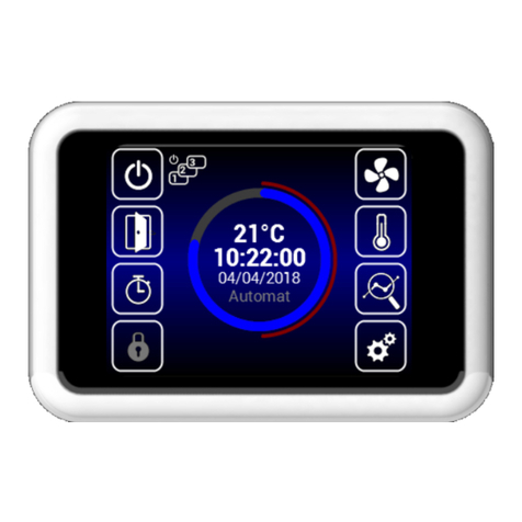
Remote control contains a touch-
screen – the device is operated by
touching the symbols on the screen.
This symbols merely inform about status, and do not indicate an error
These symbols warn of an error; by clicking on the symbol of a
warning icon a screen is shown with the given error messages
The individual MENUs are described later in this manual
page 13
page 14
page 17
Activation/deactivation
(only in standby mode)
Activating/deactivating the
specic Slave unit
Informational
icons
Warning icons
Description of main screen
Toggling between night
and day modes.
Timer
Displaying current temperature, air ow,
heating level, current time, control mode, and
displaying (day/night) mode.
Setting air ow
(for closed doors)
Setting required
temperature
(for closed doors)
Locking the controls with
a password, if the con-
troller is unlocked and
the MENU USER LOCK
has been congured
Detailed information
about boiler status
Device
settings
Night mode
DOOR mode
Informational
icon
Time mode
Warning icons
7. OPERATION
Cooling the device

14 15
2 VV. Creating innovative solutions for you and your business since 1995.
Settings can be found in these instructions in the
“SUBUNITS” menu.
Current status
MENU Settings Settings required
temperature for closed doors
Setting air ow for closed
doors
Setting date and time
This screen displays detailed status of the shutter and sensor values:
• Current set air ow (step or %), informational icons
• Air temperature for intake*, exhaust*, room temperature*, and temperature outside the building*
• (* - in the event that the necessary sensors are installed and enabled)
• Set heater power (if included)
Information
about unit type
Indication of heating blockage
(summer mode)
If there are SLAVE shutters connected, the information from them is displayed here.
Access to them is available by shifting the screen upward.
Return to previous
screen
Spatial temperature
Exterior temperature
Setting required tem-
perature
(for closed doors)
Setting air ow
(for closed doors)
Language
Setting DAY temperature
Setting NIGHT temperature
Display backlight
Parameters
Date and
time
NFC/QR CODE
Timer
Return to previous
screen
Conrm
+ return
Conrm
+ return
Displaying the required air ow
(step by 20%)
Blower power with closed doors may be limited in the menu 1616 Adv. fan
setting. After exceeding the limit, the blower power is restricted according
to the limit.
Reducing or increasing
air ow through shutters
(for closed doors)
Displaying the
current status of
air ow
Setting current date
and time
Reducing or
increasing required
temperature
Required temperature
settings-menu 09
Required power
Automatic mode = °C
In the event that heating is suspended by summer mode
(MENU - SUMMER HEATING), the “Sun” icon is displayed
here without the option to select power.
This mode can be toggled on the controls, or
using the Night/Day button attached to the
regulator.
clamp number 13, 14.
Conrm
+ return Return to main screen
7. OPERATION
SP= required temperature green color indicates active
sensor
displaying the need for servicing
mixing shutter

14 15
2 VV. Creating innovative solutions for you and your business since 1995.
7. OPERATION
Timer Language
Backlight settings
Week mode
Year mode
Time activation/deacti-
vation
Week mode Language
selection
Year mode
Where to copy
START / STOP interval
This setting is not observed in the timer mode.
When activating this eld the regulator
turns o at the set time on the timer.
Desired heating power.
CANCEL
Conrm
+ return
Go back
Return to main screen
Return to main
screen
Conrm selec-
tion
Various time modes may be set by
touching any given day.
Touch to add new time
mode
Button for copying dai-
ly plan to other days
Copy + return
Unless settings dictate otherwise, the device will transi-
tion into Standby mode once the time interval has passed.
This function does not take fan settings into consider-
ation.
Any of 10 dierent language interfaces may be selected.
Conrm
+ return
Level of backlight in
activated status
Level of backlight
in standby status
Return to main
screen

16 17
2 VV. Creating innovative solutions for you and your business since 1995.
MENU - HW SETTING
Motor 1
In the quantity of the “number
of motors” menu, select the
value “1”
Motor 10
..........
..........
GNDGND
Ad 1)
Ad 2)
Ad 3)
Ad 4)
Change mode (NO/NC)
External control contact
(NO/NC)
Error contact (NO/NC)
Ad 1) - Activation/settings of outer temperature sensor. Available selections:
None - sensor not connected/inactive
EXT-1 (45,46) - sensor connected (must be on connectors 45 and
46)
BMS - active temperature sensor and used from master system
Ad 2) - Setting the behavior of external contact input. Available selections:
None - inactive
External control - External activation/deactivation of device
Ad 3) - Not used.
Ad 4) - Number of connected EC motors on regulator: 0-10ks
Don't forget to connect the speed outputs of the motors to the
appropriate connectors
on the panel of the regulator, per the following schematic:
If the situation should occur that it is not required to check the speed output of
the motors, this function can be blocked:
And join the 1+2 connectors per the schematic below.
In this MENU you can set the detailed behavior of the individu-
al regulator inputs and outputs
7. OPERATION
Servicing menu
MENU - MODE
Use code 1616 to access the servicing MENU
1616
Select the MENU
after scrolling to
the middle of the
page and click-
ing to enter
If no engine with tacho or termo contact
is connected. Connectors 1 and 2 must be connected.
Enter menu
Enter selected
menu
Delete/go back
Only automated mode can be set for
this regulator.
Activation/deactivation of automatic
motor rotation control by temperature

16 17
2 VV. Creating innovative solutions for you and your business since 1995.
MENU - MODBUS RTU
MENU - NETWORK
IC-C Address:
1~247
Parity:
None
Odd
Even
Enabling/disabling DHCP
Manual entry of regulator
network settings:
IP address
Mask
Gate
Communication speed IC-C:
4800 Bd
9600 Bd
14400 Bd
19200 Bd
38400 Bd
This MENU allows for the setting of communications parame-
ters for the Modbus RTU
Setting PID values for the exchanger.
This MENU allows for the setting of communications parame-
ters for network interfaces
Incorrect settings can lead to inability to communicate with
the regulator
Incorrect settings can lead to poor heat exchanger function-
ing!!!
Incorrect settings can lead to inability to communicate with
the regulator
MENU - FILTER TIMER MENU - PID params
MENU - TEMPERATURE SENSOR
Current timer
status
Setting the desired time
until an alert appears on
the main screen of the
display
1000 h ~ 5000 h
Sample display of status
of fouled lter on main screen
RESET button
(use after replacing
lters with new
ones)
This MENU allows you to set the time (by motor hours) after
which an alert to replace lters is displayed, if applicable, to re-
set the timer after replacing lters
Available in Automatic Mode only.
In this menu the temperature sensor that will be used for pri-
mary temperature control can be selected
Available selections:
Room - Spatial temperature sensor (e.g. in a room)
Room BMS - Spatial temperature sensor from master system
7. OPERATION

18 19
2 VV. Creating innovative solutions for you and your business since 1995.
MENU - USER LOCK
MENU - SUMMER HEATING
Level of restriction - for more see
Ad1)
PINU entry 0000~9999
(only numeric values)
This MENU allows for setting restrictions on the control of the
regulator using panels at various levels
This MENU allows for the setting of heating restrictions in summer
months
If the outdoor temperature sensor is not set,
the “summer heating” mode operates only according to the se-
lected time and the set temperature is not assessed
Available selections:
None - Restriction not active
On/O - Only the option to activate/deactivate and access to the information menu are
accessible from the main screen.
On/O, Temp, Flow - The following are available without password: Activate/Deactivate,
Information menu,
Temperature Settings, Air Flow Settings
Full - Only the information menu is available without a password
User mode - Special user mode, see image below
End of winter season
(number of month)
Beginning of winter
season (number of month)
Activation/deactivation
of this function
Temperature limit - is
the temperature on the
“Outdoor” sensor is higher
than the setting her, the
deactivation of heating
occurs
7. OPERATION
MENU - SUBUNITS
This MENU allows for setting the behavior of other regulators
connected as "SLAVE”
This MENU is available only for units with water heat exchanger
Number of SLAVE regulations:
0 ks ~ 10 ks Ad 1)
The menu serves to dene protection of the water heat exchanger.
In the event of checking both sensors, both values
must be exceeded for the heat exchanger protection function to
be activated. If no sensor is selected, anti-freezing protection of
the heat exchanger is deactivated.
Ad 1) - Option to activate icon on the main screen that can allow for deactivating/
activating the individual SLAVE regulators. If this function is not active,
all SLAVE regulators will activate/deactivate at once.
Function disabled = Global switching/switching o of SLAVE regulators
Function enabled = From the main screen the individual SLAVE regulators can be selected
for activation/deactivation
MENU - WATER ANTIFREEZE
ROOM temperature
sensor
Water temperature
sensor

18 19
2 VV. Creating innovative solutions for you and your business since 1995.
7. OPERATION
This MENU allows for setting the behavior of other regulators
connected as "SLAVE”
MENU - WATER ANTIFREEZE
This MENU allows for setting the mixing shutters, which
intake exterior air into the interior space. This is active only in
DAY mode with Outlet limitation room enabled in MENU 37.
MENU for fan settings
After reaching the desired temperature in the space, the fan and the
heating are deactivated. During temperature drops by the set hyster-
esis,
the fan and heating once again reactivate.
Setting the shutters in mixing
mode.
Delay for instruction of
mixing mode
when toggling DAY/NIGHT
Setting minimum fan power.
Setting maximum fan
power.
When exceeding the desired
temperature by a set amount
(Fan O), the fan is deactivated.
Maximum temperature
for return water
Setting periods for
blower movement.
Only at 0:00 time and
in Standby mode.
The minimum throughput of water can be set only for analogue fan control.
This function is active in Standby mode as well.
MENU - Adv. WATER SETTING
MENU - Damper control
MENU - Fan limits
MENU for setting exhaust temperature limits.
Setting exhaust tempera-
ture limits after reaching a
temperature in the space.
If the exhaust temperature
set decreased by the desired
temperature (Room alarm),
the mixing shutter will be
closed, the contact alarm
heater will be bound and an
error will be reported.
MENU - Fan limits
MENU - OTHER SETTINGS
This MENU allows for setting other parameters
Ad 1)
Ad 1) - Option to set CAN address of control panel such that
up to 2 control panels can be connected to MASTER regulation
Options: CP 1 = control panel has address 1
CP 2 = control panel has address 2
Activation or deactivation
of automatic change
of summer/winter time

20 21
2 VV. Creating innovative solutions for you and your business since 1995.
7. OPERATION
Electrical connection - Option 1:
CP 1 CP 2
IC
CAUTION!
Each panel must have its own address.
If this is not observed, it can result in improper functioning of the regulator.
When connecting multiple panels it is necessary to set the termination elements. These can be found on
the main electronics and in the control:
Setting termination elements
Example of connecting controllers - Option 1:
63
CANH
A
CANL
GND
+12 V
B
A
B
+12 V
GND
6465 66
ON
ON
IC
CP 1 CP 2
63
CANH
A
CANL
GND
+12 V
B
A
B
+12 V
GND
6465 66
ON
ON
ON
ON
OFF
OFF
MENU - FACTORY RESET
This regulator settings MENU to default settings
Pressing the “FACTORY RESET”
button sets values in MENU 1616
to the outgoing
After completion it is recommended that you deactivate and
connect the main power supply of the regulator
Electrical connection - Option 2:
CP 1 CP 2
IC
IC
CP 1 CP 2
63
CANH
A
CANL
GND
+12 V
B
A
B
+12 V
GND
6465 66
ON
ONON
ON
Electrical connection - Option 2:
OFF
OFF
This manual suits for next models
7
Table of contents
Other 2VV Control System manuals
Popular Control System manuals by other brands

SNAP PAC BRAINS
SNAP PAC BRAINS SNAP-PAC-EB1 user guide

Lippert Components
Lippert Components Sway Command Install manual

Siemens
Siemens SINUMERIK 828D Turning Training manual

Sienci Labs
Sienci Labs LongMill V1 Assembly manual

GEA
GEA T.VIS E-20 Operating instruction

Cleveland
Cleveland HA-SE-CC Specifications