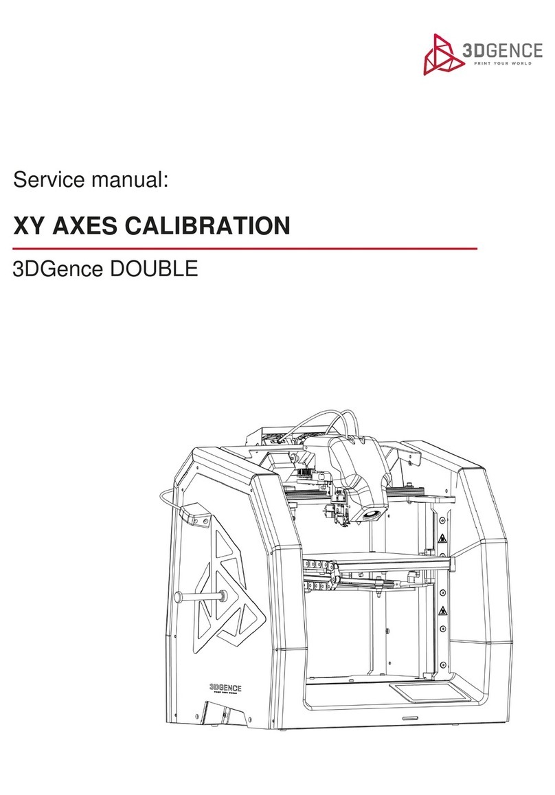
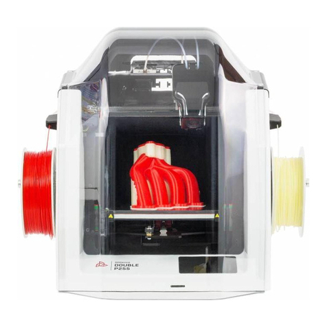
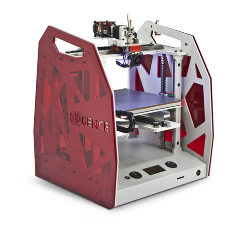
3DGence ONE User manual

USER’S MANUAL
3DGence ONE

page 2of 45
3DGence ONE | version 07.2018
Contents
I INTRODUCTION ............................................................................................................................................................................4
1. INTRODUCTORY COMMENTS.................................................................................................................................................4
2. MATERIALS FOR PRINTING.....................................................................................................................................................4
3. SYMBOLS ................................................................................................................................................................................5
3.1. List of symbols used in the manual.................................................................................................................................5
3.2. Indicator lights ................................................................................................................................................................6
4. SAFETY MEASURES.................................................................................................................................................................6
4.1. General information .......................................................................................................................................................6
4.2. Relocating the printer.....................................................................................................................................................7
4.3. Choosing proper installation place for the printer .........................................................................................................8
4.4. Before starting the printer............................................................................................................................................10
II DESCRIPTION OF PRINTER .........................................................................................................................................................11
1. CONSTRUCTION OF PRINTER ...............................................................................................................................................11
2. CONTENTS OF EQUIPMENT..................................................................................................................................................14
3. USER INTERFACE ..................................................................................................................................................................16
3.1. Main panel....................................................................................................................................................................16
3.2. PAUSE and START buttons ............................................................................................................................................17
3.3. LCD display....................................................................................................................................................................17
3.4. MENU............................................................................................................................................................................19
III PREPARATION FOR WORK ........................................................................................................................................................24
1. FIRMWARE UPDATE .............................................................................................................................................................24
2. CONNECTING AND STARTING PRINTER ...............................................................................................................................24
3. CALIBRATION OF HEATBED ..................................................................................................................................................25
3.1. Indication for calibration of heatbed............................................................................................................................25
3.2. Heatbed calibration procedure ....................................................................................................................................25
4. PRINTING MATERIAL APPLICATION PROCEDURE.................................................................................................................26
4.1. Mounting filament........................................................................................................................................................27
4.2. Filament removal..........................................................................................................................................................28
4.3. Changing filament during printing................................................................................................................................28
IV FIRST PRINTOUT .......................................................................................................................................................................30
1. LAUNCHING SD CARD CODE.................................................................................................................................................30
2. EVALUATION OF OPERATIONAL QUALITY OF PRINTER ........................................................................................................31
V SOFTWARE ................................................................................................................................................................................32
1. INTRODUCTION....................................................................................................................................................................32
1.1. Quality guarantee .........................................................................................................................................................32
2. INSTALLATION ......................................................................................................................................................................32
VI POST PRINTING OPERATIONS ..................................................................................................................................................33
1. REMOVING THE PRINTOUT FROM THE DEVICE ...................................................................................................................33

page 3of 45
3DGence ONE | version 07.2018
2. CLEANING.............................................................................................................................................................................33
2.1. Cleaning the hotend .....................................................................................................................................................33
2.2. Cleaning heatbed..........................................................................................................................................................34
3. SWITCHING THE PRINTER OFF .............................................................................................................................................34
VII hOTEND REPLACEMENT ..........................................................................................................................................................36
VIII CALIBRATION OF AXES ...........................................................................................................................................................38
IX MAINTENANCE AND SERVICE ACTIVITIES.................................................................................................................................40
1. AUTOCOMPENSATION .........................................................................................................................................................40
X DICTIONARY...............................................................................................................................................................................42

page 4of 45
3DGence ONE | version 07.2018
Fig. 1 Filament spool
I INTRODUCTION
1. INTRODUCTORY COMMENTS
Thank you for choosing 3DGence ONE 3D printer. The following manual shall introduce you to the world of 3D printing. It
enables you to work your way around it, ensures high quality working results and allows safe and effective exploitation of the
device for a long time. 3DGence mission is to offer exclusively the highest class of devices that meet expectations of both
professionals and amateurs.
On the last pages of this User's Manual there is the dictionary of terms and concepts connected with 3D printing. The dictionary
will facilitate understanding the professional terminology and explain some terms appearing in this User's Manual.
The User's Manual contains information necessary for proper and safe use of the printer. Read the entire User's Manual
carefully before using the printer.
The persons who have not read the User's Manual must not use the printer. Wrong use may damage the printer or cause bodily
injuries or even endanger the life of the operator.
Before starting the operation of 3DGence DOUBLE printer, the user must read the entire User's Manual and accept the
instructions and exceptions included in the User's Manual.
2. MATERIALS FOR PRINTING
FFF technology (Fused Filament Fabrication) used by 3DGence ONE printer consists in depositing plasticized thermoplastic
material (plastic) layer by layer. This plastic is the printer's operating material. The thermoplastic material is used in the form
of a filament with a precisely defined diameter, wound on a spool (fig. 1). 3DGence ONE printer uses the filament with the
diameter of 1.75 mm.

page 5of 45
3DGence ONE | version 07.2018
There are many different filament materials. Consumables are usually made of substances such as: ABS, PLA, nylon with various
admixtures (e.g. tribo-filaments) nylon, elastic materials, enriched with metals, wood, chalk, carbon fiber, graphite and many
others. There are many types of materials such as changing colors, luminescent or made of plant fibers. The use of particular
material depends primarily on individual requirements and customer expectations - filaments have a variety of properties such
as esthetic, mechanical or temperature features. Any used material requires specific, precisely defined parameters for the
correct printing. Growing choice of new 3D printing materials makes FFF printing one of the most universal tools on the market.
3DGence ONE printer can use a wide range of printing materials available in many colours, if the material meets the following
criteria:
•the diameter of the filament should be 1.75 mm, with a tolerance of +/- 0.05mm,
•the suggested printing temperature should not exceed 265°C.
The Certified Material Base, available at www.3dgence.com, has been created for 3DGence ONE printer.
3DGence is not responsible for the quality of printouts made of the materials other than those included in the Certified Material
Base and for damage caused by the use of such materials as well as it does not provide support for the quality of the printouts
made of the filaments other than those included in the Certified Material Base.
3. SYMBOLS
3.1. List of symbols used in the manual
Throughout this User's Manual the following symbols are used. They identify the situations that are potentially dangerous to
health or may cause damage to the printer. Always adhere to the warning symbols. Negligence may cause the printer's damage
excluded from the guarantee cover as well as bodily injuries.
DANGER:
The situation or procedure described is potentially dangerous and it may result in damage to the printer or
cause injury to the operator. Exercise care.
ATTENTION:
The situation or procedure described is potentially dangerous and it may result in damage to the printer.
Exercise care.
PROTECTION:
Protective gloves, delivered with the printer, must be worn when performing the activities described. Put on
protective gloves before performing these activities.

page 6of 45
3DGence ONE | version 07.2018
3.2. Indicator lights
3DGence ONE printer is equipped with LED backlight located under the printer's upper plate. The LED backlight illuminates the
printout during the printer operation and is also a form of signalling device. The description of all backlight colours and their
meanings is given below (table 1).
Tab. 1Meaning of backlight colours in 3DGence ONEprinter
COLOUR
MEANING
Green
Safe temperature of the heatbed (below 40°C).
After completed printing, the printout can be safely unloaded.
Red
Heatbed temperature exceeds 40°C.
Do not touch the heatbed –there is a risk of burns.
After completed printing, do not remove the printout from the heatbed until the
backlight turns green.
White
The printer is working. The heatbed is hot - do not touch it.
There is a serious risk of burns.
Yellow
Failure of the heating devices. If the hotend has been installed correctly,
immediately disconnect the printer from power supply and contact the service
department.
The backlight colour indicates the heatbed temperature not the hotend temperature! The hotend temperature is
shown only on the display!
4. SAFETY MEASURES
The information below describes the correct operating conditions of 3DGence ONE printer. Failure to comply with the
indications and contraindications may significantly reduce the life of the printer, violate the guarantee conditions or endanger
the health of users.
4.1. General information
The printer must not be installed:
•in open space, outdoors,
•in damp places or in places at risk of flooding,
•in the vicinity of volatile and flammable substances,
•near concentrated acids, caustic vapours or corrosive substances,
•in places easily accessible to children,
•using the network without a protective earth lead (PE) and residual –current device to avoid electric shock
in the event of a malfunction of the device.
Do not:
•touch the printed model, heatbed or hotend during printing,
•insert any body parts or objects into the printer's working area during printing –the printer may get damaged
or the operator may get injured,
•touch the heated nozzle with your hands, even with protective gloves,
•bend over the heated hotend or the hotend area during the printer operation - there is a risk of facial burn
injuries,
•touch live parts,
•touch linear guides and trapezoid bolts during the printer operation,
•operate the printer with wet hands,
•put any objects on or under the printer's table –during the printer operation or when the printer is at
standstill,
•put containers with liquids on the printer,
•leave the working printer without the control of an adult who is able to take appropriate steps in the event
of a failure,

page 7of 45
3DGence ONE | version 07.2018
•leave the working printer in a room with children or animals,
•disassemble the printer or hotends; make unauthorized repairs –the printer or hotends may get damaged.
3DGence ONE printer heats up to temperature above 250°C; the device has many elements, which make
unpredictable, rapid movements during printing. It is forbidden to put any objects or parts of body inside the device
when operating!
Adhere to the following instructions:
•when disconnecting the plug from the power source, pull the plug by its housing not by the cable,
•disconnect the printer from the power source before any repair or maintenance activities,
•make sure that the mains voltage corresponds with the printer's specifications,
•protect the power lead and plug against damage,
•disconnect the power plug before relocating the printer,
•disconnect the power plug if the printer will not be used for a longer period of time,
•periodically remove external contaminations from the hotend nozzles (using non-flammable material),
•always wear protective gloves when operating the printer,
•ensure the possibility of quick response in the event of a break-down/print failure,
•each time before starting the printer, carefully inspect the direct vicinity of the printer and remove all obstacles and
contaminations with which the printer could collide or which could in any way hinder the free movement,
•guarantee free access to the printer for the operator, throughout the printer operation.
Heated heatbed and hotends remain hot even after completed printing. Check their temperature on the display before
touching them (fig. 2) or wait at least 30 minutes after switching the printer off (e.g. in order to clean or remove the
model, change the hotend, etc.)
4.2. Relocating the printer
To ensure the safety of the user and to avoid accidental damage to the printer, the following rules must be followed when
relocating the printer:
•before relocating the printer, switch it off and disconnect it from the power source,
•the printer should be cooled down, the operating material and all loose elements and accessories should be removed from
the printer,
•the printer should be lifted only by the handles designated for this purpose (fig. 3); do not lift the printer by any other
elements,
•the printer should not be carried by children and the elderly due to its significant weight (about 20 kg).
Fig. 2 Temperature indications for: 1. hotend | 2. heatbed

page 8of 45
3DGence ONE | version 07.2018
Fig. 3 Locations of handles for printer handling
4.3. Choosing proper installation place for the printer
The printer installation place should meet the following conditions:
•the printer should work at room temperature,
•the printer is not designed for work in a dusty environment,
•ventilation suitable for a room size should be ensured,
•the printer should be installed on a hard and stable ground,
•the printer should not be exposed to direct sunlight,
•ensure sufficient free space around the printer based on the printer's external dimensions and working range
of the axes (fig. 4, 5),
•keep the printer away from other heat sources and draughts,
•the printer's installation place should be equipped with a 230V/50Hz mains socket (110V version for the USA
market),
•the device should be connected to a mains socket with grounding to avoid electric shock in the event of a
malfunction of the device,
•uninterruptible power supplies (UPS) should be used in order to ensure that the printing process is not
stopped in case of instantaneous current decay.

page 9of 45
3DGence ONE | version 07.2018
Fig. 4 The maximum dimensions of the printer taking into account the extreme
positions of the heatbed –right side view
Fig. 5 The maximum external dimensions of the printer (accessories included) and markings of X, Y, Z axes

page 10 of 45
3DGence ONE | version 07.2018
4.4. Before starting the printer
Before each use of the printer, make sure if the following conditions are met:
•check whether the cables have no visible fraying or other damage. In case of damage of cables, you should immediately
notify the 3DGENCE company’s technical service department. In such circumstances, the user is prohibited from
connecting the device to the power supply and/or making repairs on their own,
•make sure the filament is not dirty, broken, bent or tangled on the spool,
•make sure that in the printer working area there are no items or leftover prints that could cause a jam or damage the
machine,
•check the X and Y axes, and make sure that nothing is blocking their movement. Check that the toothed belts are pulled
tight and have no damage,
•check whether Z-axis stopwatch (fig. 6) is not damaged, broken or bent and if it matches Z-axis limit switch (aims at the
notch in limit switch),
•check the correct operation of thermistors (temperature sensors), hotend and heatbed. To do this, start the heating of the
hotend and heatbed and check if temperature parameters on LCD display are rising,
•check that in the area of the printer there are no objects or persons who might be injured as a result of the printer
operating.
Fig. 6. Z-axis limit switch and stopwatch in their.

page 11 of 45
3DGence ONE | version 07.2018
II DESCRIPTION OF PRINTER
1. CONSTRUCTION OF PRINTER
To facilitate learning and operating 3DGence ONE printer, the manual contains a number of figures (diagrams) (fig. 7–12) with
descriptions of the most important components of the device. Reading the figures and terms can help in understanding
terminology widely used in 3D printing.
Fig. 7. 3DGence ONE printer view (left side):
1. Extruder / 2. Z-axis limit switch / 3. Z-axis timer/stopwatch / 4. Heatbed / 5. Filament spool holder
6. Filament cleaner / 7. Control buttons / 8. LCD screen / 9. MENU buttons / 10. SD card slot
11. Power button

page 12 of 45
3DGence ONE | version 07.2018
Fig. 8. 3DGence ONE printer front view (right side):
12. X-axis guide / 13. Ball screws / 14. Y-axis guide / 15. Extruder elements
Fig. 9. 3DGence ONE printer view (left side):
16. USB port A (flash drive) / 17. USB port B (computer) / 18. Power inlet socket
19. Fan (warning: do not obstruct)

page 13 of 45
3DGence ONE | version 07.2018
NOTE:
After removing printer from the package, make sure that the extruder lever (element 20) is in correct position
(as shown in fig. 10) and if there is a 7-8 mm space between clamp adjustment screw (element 21) and
extruder clamp (element 23).
Fig. 10. Extruder and head module (front view)
20. Extruder (open/close) lever / 21. Clamp adjustment screw / 22. Knurl
23. Extruder clamp / 24. Tensometers / 25. Button releasing the hotend / 26. Hotend
27. Printout cooling fan
Fig. 11. 26. Hotend / 27. Cooling fans.

page 14 of 45
3DGence ONE | version 07.2018
NOTE:
Figure 11 presents the print head. The nozzle (element 26), accumulates contaminations in the process the
printing. Deposits accumulated on the nozzle should be regularly removed with the use of non-combustible
cleaning substance. For more information on cleaning the nozzle see chapter „Post-printing operations”, section
2.1.
Figure 12 shows locations of hot zones marked in red, where the operating machine reaches a high temperature. Touching
any elements placed in hot zones before their complete cooling may result in burns!
Zone 1: hotend and extruder zone. Working temperature to 265°C.
Zone 2: heatbed zone; working temperature to 160°C.
2. CONTENTS OF EQUIPMENT
The complete 3DGence ONE set includes the following items. Most of them is placed in the flat box shown in fig. 13.
•3DGence ONE printer,
•spatula for removing printouts (1),
•USB cable (2),
•filament spool holder (Note: left-hand thread!) (3),
•tweezers (4),
•SD memory card (5),
•USB memory stick with software (6),
•cleaner with handle and teflon wire (7),
•power cable (8),
Fig. 12. 1. Extruder / 2. Heatbed.

page 15 of 45
3DGence ONE | version 07.2018
•protective gloves (9),
•filament spool,
•hotend with nozzle with a diameter of 0.4 mm (already installed),
•panels made of polycarbonate (fig. 14) (sides, depending on the color version: red, blue or orange) (11),
•additional hotends (optional) (10).
Fig. 13. Distibution of accessories in the package.
Fig. 14. Panels made of polycarbonate (sides, depending on the color version: red, blue or orange).

page 16 of 45
3DGence ONE | version 07.2018
3. USER INTERFACE
3.1. Main panel
Below is shown the main panel of 3DGence ONE. It consists of 11 buttons, divided into two functional groups. The functions
of two of them (Pause/Start) are discussed in the next subsection.
Right panel
Buttons in this group are for navigating MENU. They provide access to all parameters in the menu and allow adjusting
their values.
Function of buttons (fig. 15):
1. Navigation key OK - entering MENU and confirming selection.
2. Upwards Menu navigation button (and values changer).
3. Instant file preview on SD card.
4. Key down navigation menu (and values changer).
5. Menu Navigation button and menu return.
Left panel
WARNING:
Left control panel operates outside of traffic restrictions (by micro switches), damage caused by improper use
is not covered by the warranty (buttons from 1 to 4).
Function of buttons (fig. 16):
1. Upwards heatbed adjustment button, one click moves the heatbed by 0,025mm, which enables adjusting the height of the
heatbed during printing (the button is active after referencing Z axis).
2. Add filament button (active after the hotend reaches 185°C). Allows control of feeding the material during printing. The
button allows to fill the unfinished spaces/losses on individual layers or fill up the hotend before the commencement
of printing.
Fig. 15. 3DGence ONE navigation panel: 1st group of buttons.
Fig. 16. 3DGence ONE navigation panel: 2nd group of buttons.

page 17 of 45
3DGence ONE | version 07.2018
3. Downwards heatbed adjustment button, one click moves the heatbed by 0,025mm, which enables adjusting the height of
the heatbed during printing (the button works after referencing Z axis).
4. Filament recognition button (active from 185°C). Allows removing material from the hotend.
Applies to PLA material, in the case of ABS, set hotend temperature to 240°C to use quick access keys.
WARNING:
Buttons in point 2 and 4 are to be used after the head has warmed up to the temperature recommended by
the manufacturer of the material. If not used properly, it may cause damage to the hotend.
3.2. PAUSE and START buttons
To increase functionality and facilitate the use of the printer, 3D Gence ONE unit has been equipped with PAUSE button
(fig. 17) (1) that has the following functions:
•a single-press will stop the printing process,
•a double-press will hold the printing process and the departure of the nozzle to X and Y axes base position.
This function allows modifying the printed object e.g.: inserting a cap (or other object) to a specially prepared socket and
further printing on the surface of the inserted object, changing the color of the filament, or, if the printing material runs out,
replacing an empty spool. However, for the replacement of printing material it is recommended to use filament replacement
guide „Filament change” from the MENU. Note that the added objects cannot protrude beyond the currently existing printing
surface; otherwise the hotend can collide with the added object and be damaged.
When changing the printing material, it is recommended to hold the printing process at the stage of printing the filling, which
reduces the risk of possible defects on the surface of printing model.
WARNING:
Always wear protective gloves for any manual operations within the working area.
To resume the printing process press START button (button 2, fig. 17), regardless of whether PAUSE button was pressed
once or twice.
3.3. LCD display
LCD display enables accessing all MENU functions and direct control of important parameters of 3DGence ONE printer
such as hotend and heatbed temperature. Location of particular parameters on LCD panel is presented below.
After starting the printer it displays the following information (fig. 18):
Fig. 17. 3DGence ONE navigation panel: PAUSE (1) i START (2).

page 18 of 45
3DGence ONE | version 07.2018
3DGence ONE printer displays the following information:
1. Preset hotend temperature,
2. Current temperature of hotend (as indicated by temperature sensor),
3. Preset heatbed temperature,
4. Current temperature of heatbed (as indicated by temperature sensor).
5. Percentage of current power of printout cooling fans.
After starting printing, LCD panel displays the following information (fig. 19):
Information currently displayed:
1. Preset hotend temperature,
2. Current temperature of hotend (as indicated by temperature sensor)
3. Preset introduced heatbed temperature,
4. Current temperature of heatbed (as indicated by temperature sensor)
5. Percentage of current power of printout cooling fans.
6. Printing progress panel (graphic presentation and percentage).
Temperature parameters and fan power can be changed during the printing process. Parameters can be manually adjusted for
the purpose of printing process optimization. For example, strong airflow should not be used during printing the first layer, for
this reason the obtained read may be 0%. Machine code automatically starts the cooling fan at the appropriate stage of
printing. Fan settings can be changed from the MENU - Fan Speed.
LCD panel can also display information on total printing time and the amount of printed material from the initial starting of the
printer. To access this data press the arrow down button (4, Fig. 14) on the right side of the panel from the main MENU.
Fig. 18. 3DGence LCD display after turning on.
Fig. 19. 3DGence LCD display while printing.

page 19 of 45
3DGence ONE | version 07.2018
3.4. MENU
3DGence ONE has an extensive user interface allowing full control of the printer without connecting it to a computer. For
accessing MENU press OK button on the main panel (button 1, Fig. 14). To navigate MENU use navigation buttons on the
right side of the panel (see chapter “Main Panel” - buttons 2, 3, 4, 5, Fig. 14).
Diagram of the Menu and description of available functions are presented below. The displayed functions of menu can
change depending on the printer’s current operation mode (active or idle). Here is an example of menu in idle mode:
The symbol shown stands for choosing the option for up and down parameter regulation after pressing OK
button.
Fig. 20. Main menu in idle mode.

page 20 of 45
3DGence ONE | version 07.2018
From this level you can enter a given selection settings:
Fig. 21. PREPARE menu.
Fig. 22. PRINT menu.
Other manuals for ONE
3
Table of contents
Other 3DGence 3D Printer manuals

3DGence
3DGence INDUSTRY F420 User manual

3DGence
3DGence DT3 User manual

3DGence
3DGence ONE User manual

3DGence
3DGence DOUBLE User manual

3DGence
3DGence INDUSTRY F340 User manual

3DGence
3DGence DOUBLE P255 User manual

3DGence
3DGence INDUSTRY F340 User manual

3DGence
3DGence ONE User manual

3DGence
3DGence DOUBLE P255 Guide

3DGence
3DGence ONE User manual