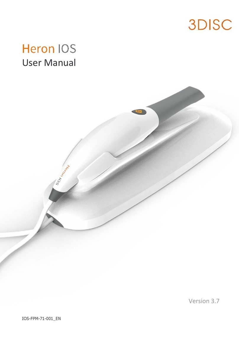
3Disc Fire CR dental User manual

Service Manual
Hardware revisions AH and later.

1

2
FireCR Dental Computed Radiography
Reader
Doc No.: TM-821-EN
Rev: 1 Sep 2016
Part No.: CR-FPM-11-021-EN
3DISC, FireCR, FireCR Dental and Quantor are trademarks of 3D Imaging & Simulations Corp,
South Korea, and its affiliates. All other trademarks are held by their respective owners and are
used in an editorial fashion with no intention of infringement.
The data in this publication are for illustration purposes only and do not necessarily represent
standards or specifications, which must be met by 3D Imaging & Simulations Corp.
All information contained herein is intended for guidance purposes only, and characteristics of the
products and services described in this publication can be changed at any time without notice.
Products and services may not be available in your local area. Please contact your local sales
representative for availability information.
3D Imaging & Simulations Corp. strives to provide as accurate information as possible, but shall
not be responsible for any typographical error.
© Copyright 2016 3D Imaging & Simulations Corp, all rights reserved, printed, and published in
South
Korea by 3D Imaging & Simulations Corp.

3
Table of contents
Parts removal/replacement
Disassembly ..................................................................................................................... 5
Replacing the door assembly ................................................................................................................ 10
Replacing the covers assembly ............................................................................................................. 10
Replacing the top cover ......................................................................................................................... 10
Replacing the side cover ........................................................................................................................ 10
Replacing the inner cover ...................................................................................................................... 11
Replacing the bottom cover .................................................................................................................. 11
Replacing the rear cover ........................................................................................................................ 11
Replacing the front board...................................................................................................................... 11
Replacing the left PSD sensor................................................................................................................ 13
Replacing the laser module ................................................................................................................... 14
Replacing the optics bracket ................................................................................................................. 15
Replacing the eraser .............................................................................................................................. 19
Replacing the right PSD sensor ............................................................................................................. 20
Replacing the PMT assembly ................................................................................................................. 21
Replacing the power board ................................................................................................................... 23
Replacing the main board ..................................................................................................................... 24
Replacing the BLDC driver board .......................................................................................................... 27
Replacing the mains power switch........................................................................................................ 28
Replacing the SD memory card ............................................................................................................. 30
Replacing the RFID board ...................................................................................................................... 31
Replacing the tray assembly.................................................................................................................. 34
Replacing the bottom board ................................................................................................................. 36
Replacing the stage base assembly....................................................................................................... 39
Replacing the drive belt ......................................................................................................................... 45
Replacing the stepper motor................................................................................................................. 47
Updating the firmware after parts replacement ................................................................ 49
Description of parts information ................................................................................................. 50
ADC offset verification and adjustment ...................................................................................... 51
PMT gain verification and adjustment ........................................................................................ 54
Scanner calibration...................................................................................................................... 56

4
This manual covers replacement of hardware for revision AH and later.
The hardware revision of the unit can be identified using the serial number on the back of the unit.
The centre part of the serial number contains two decimals, and 4 alphanumerical characters, the
last two identifies the hardware revision.
Please ensure these are AH or later e. g. FR-11-00DHAH-XXXXXX, on some units the serial has been
changed to a UDI, the hardware revision for these can be verified like shown in the following
example: (1)08809466040214(11)160502(10)FR1100AH(21)XXXXXX.

Parts removal/replacement
Disassembly
1. Set the reader into “sleep mode” by pressing on the half-moon symbol on the display.
2. Switch off the reader on the back and disconnect all cables.
Ethernet
Power switch
Off
On
USB socket
Power inlet

6
3.
Remove the 4 screws using a Philips #2 screwdriver and remove the rear cover.
4.
Push the door inwards and upwards to gain a decent handhold on the inside of the front cover
(1), then pull outwards and upwards to remove the front cover from the rest of the unit (2).
5.
Turn the front cover over to gain access to the cables.
1 2

7
6.
Tip the lock of the ribbon cable and disconnect the ribbon cable (1) and motor power cable (2)
from the TFT LCD display driver board.
7.
Put the reader on the side being careful not to damage it, and remove the 6 screws using a
Philips #2 screwdriver.
1 2

8
8.
Set the reader back upright and carefully lift the top cover off.

9
9.
Remove the 4 screws fastening the inner chassis using a 2.5 mm hex key and lift it off.

10
Replacing the door assembly
1.
Follow step 1, 2, 4, 5 and 6 of Disassembly.
2.
Replace the door assembly and install in reverse order.
3.
Calibrate the LCD as described in the LCD calibration section.
Replacing the covers assembly
1.
Follow step 1 through 9 of Disassembly.
2.
Replace the covers and install in reverse order.
Replacing the top cover
1.
Follow step 1 through 8 of Disassembly.
2.
Turn the cover over and release the locks fastening the top cover onto the side cover.
3.
Replace the top cover and install in reverse order.
Replacing the side cover
1.
Follow step 1 through 8 of Disassembly.
2.
Turn the cover over and release the locks fastening the top cover onto the side cover.
3.
Replace the side cover and install in reverse order.
4.
Fasten the serial number sticker on the back of the cover.

11
Replacing the inner cover
1.
Follow step 1 through 9 of Disassembly.
2.
Replace the inner cover and install in reverse order.
Replacing the bottom cover
1.
Follow step 1 through 8 of Disassembly.
2.
Put the scanner onto its side and remove the 6 screws using a 2.5mm hex key and remove the
bottom cover.
3.
Replace the bottom cover and install in reverse order.
Replacing the rear cover
1.
Follow step 1 through 3 of Disassembly.
2.
Replace the rear cover and install in reverse order.
Replacing the front board
1.
Follow step 1 through 9 of Disassembly.
2.
Unlock (1) and disconnect (2) the ribbon cables from the front board.
3.
Unplug the connectors from the front board.
1
2
1
2

12
4.
Remove the 3 screws using a 2.5 mm hex key.
5.
Replace the front board and install in reverse order.

13
Replacing the left PSD sensor
1.
Follow step 1 through 9 of Disassembly.
2.
Remove the 2 screws using a 2.5 mm hex key.
3.
Cut the cable tie and disconnect the PSD sensor from the front board PCB.
4.
Replace the left PSD and install in reverse order.

14
Replacing the laser module
1.
Follow step 1 through 9 of Disassembly.
2.
Disconnect the BLDC motor (1) and laser (2) from the front board.
3.
Remove the 3 screws using a 2.5 mm hex key letting the front board hang loose.
4.
Remove the 4 screws using a 2.5 mm hex key.
5.
Replace the laser module and install in reverse order.
1
2

15
Replacing the optics bracket
1.
Follow step 1 through 9 of Disassembly.
2.
Disconnect J1 and J4 from the bottom board.
3.
Unlock (1) and disconnect (2) the ribbon cable from the front board.
4.
Put the scanner onto its side and remove the 6 screws using a 2.5mm hex key and remove the
bottom cover.
J1
J4
1
2

16
5.
Remove the 2 screws fastening the left PSD using a 2.5 mm hex key.
6.
Rotate the unit to the other side and remove the 2 screws fastening the right PSD using a 2.5
mm hex key.
7.
Cut the cable tie and disconnect the eraser from the front board.

17
8.
Remove the 4 screws fastening the bracket using 3 mm hex key.
9.
Carefully lift the optics assembly out of the unit.
10.
Remove the 4 screws from the bracket using a 2.5 mm hex key.
11.
Remove the 2 screws fastening the eraser using a Philips #1 screwdriver.
12.
Remove the eraser (1) while guiding the wires through the eraser cover (2).

18
13.
Replace the optics bracket and install in reverse order.
1
2

19
Replacing the eraser
1.
Follow step 1 through 9 of Disassembly.
2.
Cut the cable tie and disconnect the eraser from the front board.
14.
Remove the 2 screws fastening the eraser using a Philips #1 screwdriver.
15.
Remove the eraser (1) while guiding the wires through the eraser cover (2).
3.
Replace the eraser and install in reverse order.
1
2
Table of contents
Other 3Disc Dental Equipment manuals
Popular Dental Equipment manuals by other brands

Kulzer
Kulzer PALA Palamat elite operating instructions

Garrison
Garrison eZr Instructions for use

KaVo
KaVo MASTERmatic LUX M10 L Instructions for use

ShenPaz
ShenPaz Zirconia Blazir Get started guide

Dentsply Neytech
Dentsply Neytech Prime&Bond NT Instructions for use

NSK
NSK Pana-Max PLUS PAP-MU 5H Operation manual