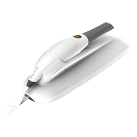
3Disc Heron IOS User manual

IOS-FPM-71-001-3.1_EN
User Manual
Version 3.4.x

Document
Software Version
Date
Heron™ IOS User Manual
IOS-FPM-71-001
1.0
08.01.2018
2.0
10.01.2019
3.0
01.01.2020
3.4
09.20.2021
3.4.x
10.27.2021
3.4.x
11.09.2021
3.4.x
11.23.2021
Comeandjointhe growing
3disc.com


Introducing the Heron™ IOS..............................................6
1.1
Introduction ........................................................................................................................... 6
1.2
What’s new in this version........................................................................................................ 6
1.3
Indications supported .......................................................................................................... 6
1.4
Certification and compliance ............................................................................................... 6
1.5
Regulatory ........................................................................................................................... 7
1.6
Intended Use ....................................................................................................................... 7
1.7
Classifications ...................................................................................................................... 7
2.
Components Overview ..................................................8
2.1
Hardware Components........................................................................................................ 8
2.2
Software Components ......................................................................................................... 8
3.
System Requirements and Specifications.......................9
3.1
System Specifications .......................................................................................................... 9
3.1.1
Scanner Specifications .............................................................................................. 9
3.1.2
Scanning Process
..................................................................................................... 9
3.2
Software output and design software compatibility ......................................................... 10
3.3
Computer Requirements ................................................................................................... 10
3.4
Environment Conditions .................................................................................................... 11
3.5
Power Input ....................................................................................................................... 11
3.6
Reusable Tips
.................................................................................................................... 11
3.7
Scanner Docking Base andHandpiece................................................................................ 12
3.8
Calibration ......................................................................................................................... 12
3.9
Wall Mount Installation Instructions (Optional)................................................................ 13
4.
Setting up your Heron™ IOS .........................................14
4.1
Connecting Heron™ IOS ..................................................................................................... 14
4.2
Launching HeronClinic™ .................................................................................................... 16
4.2.1
Setting Up A HeronClinic™ User Account ............................................................... 16
4.2.2
Connecting Heron™ IOS To HeronCloud™ .............................................................. 17
4.3
Getting Started With HeronClinicTM .................................................................................. 18
4.4
Configuring HeronClinicTM Settings.................................................................................... 20
5.
Using HeronClinicTM .....................................................27
5.1
Managing Patient cases..................................................................................................... 27
5.2
The HeronClinicTM Scan Workflow..................................................................................... 29
5.3
Before You Scan................................................................................................................. 33
5.3.1
Operating the scanner ............................................................................................ 33
5.3.2
Using the Scanner Tip ............................................................................................. 34
5.3.3
The Scanning Live View........................................................................................... 35
5.4
Recommended Scan Workflow ......................................................................................... 36
5.4.1
Scanning the MaxillaryArch .................................................................................... 36

Page 5
5.4.2
Scanning the MandibularArch ................................................................................ 39
5.4.3
Trimming scans............................................................................................................ 40
5.4.4
Using the Quality Map tool..................................................................................... 40
5.4.5
Bite Alignment ........................................................................................................ 41
5.4.6
Auto-Realignment................................................................................................... 45
5.4.7
Using Bite Alignment Tools ..................................................................................... 46
5.4.8
Finalizing A Patient Case ......................................................................................... 47
6.
Communicating With Labs ...........................................49
6.1
Linking a HeronClinic™ account to HeronCloud ................................................................ 49
6.2
Configuring a Connection with a Lab in HeronCloud ......................................................... 50
6.3
Managing Case Details in HeronCloud............................................................................... 51
6.4
Configuring HeronCloud Settings ...................................................................................... 52
7.
Maintenance................................................................55
7.1
Cleaning the Handpiece ..................................................................................................... 55
7.2
Cleaning and Sterilization ofTip......................................................................................... 55
7.3
Disposal ............................................................................................................................. 57
7.4
Calibration ......................................................................................................................... 57
8.
Safety Guidelines and Warnings...................................58
8.1
Warnings and Symbols....................................................................................................... 58
8.2
General Guidelines ............................................................................................................ 58
8.3
General Warnings .............................................................................................................. 59
8.3.1
System Modification ............................................................................................... 59
8.3.2
Approved Software ................................................................................................. 59
8.3.3
Equipment Failure................................................................................................... 59
8.4
Mechanical Hazards .............................................................................................................. 59
8.4.1
Moving Parts ........................................................................................................... 59
8.4.2
Dropped Equipment................................................................................................ 60
8.4.3
Base
........................................................................................................................ 60
8.5
Electrical Safety.................................................................................................................. 60
8.5.1
Electrical Shock
...................................................................................................... 60
8.5.2
Stress on Cables ...................................................................................................... 60
8.6
Eye Safety .......................................................................................................................... 61
8.7
Hygiene.............................................................................................................................. 61
8.8
During Systems Operation ................................................................................................. 62
8.9
EMC Guidance and Declaration ......................................................................................... 62
9.
Support, Warranty and RepairService..........................69
9.1
Support .............................................................................................................................. 69
9.2
Standard Warranty ............................................................................................................ 69
9.3
Repair Service .................................................................................................................... 70
9.4
Out of Warranty Repair Service......................................................................................... 70

Introducing the Heron™ IOS
1.1
Introduction
Thank you for purchasing the Heron™ IOS from 3DISC. The Heron™ IOS is
designed and developed to produce high-quality digital intraoral scans or
models, for dental restoration or analysis.
The Heron™ IOS solution is designed with you as a dentist and your patient in
mind. The scanner is lightweight, small and easy to use, enabling fast, accurate
scanning and enhanced patient experience.
Combined with the HeronClinic 3D Scanning and Case Management software,
and the HeronClinic cloud platform for ordering and communicating with labs,
the Heron IOS solution provides an easy-to-use, intuitive and fully digital
experience. Enjoy your new intraoral scanner solution!
1.2
What’s new in this version
This document update incorporates minor corrections and modifications to
the Heron IOS User Manual 3.4.
1.3
Indications supported
The software enables you to select the following indications* when filling out
orders for restoration:
·
Conventional crowns
·
Anatomic crowns
·
Copings
·
Provisional crowns
·
Anatomical pontics
·
Reduced pontics
·
Provisional pontics
·
Inlays/Onlays
·
Implant abutments
·
Implant-based bridges
·
Tooth-based bridges
·
Orthodontic aligners
·
Nightguards
·
Splints
·
Retainers
·
Bleach trays
·
Sleep appliances
·
…
* Verify with your dental lab or service provider about their capabilities to
produce particular indications.
1.4
Certification and compliance
The system has been tested and conforms to the following standards:

Page 7
•
IEC 60601-1, Medical electrical equipment - Part 1: General requirements for
basic safety and essential performance
•
IEC 60601-1-2, Medical electrical equipment - Part 1-2: General requirements
for basic safety and essential performance - Collateral Standard:
Electromagnetic disturbances
- Requirements and tests:
•
IEC 62471, Photobiological safety of lamps and lamp systems
1.5
Regulatory
The Heron™ IOS is manufactured and marketed in accordance with US FDA
Regulations and EU Medical Device Regulation 2017/745.
1.6
Intended Use
The Heron™ IOS is an optical impression system. It is used to record the
topographical characteristics of teeth, dental impressions, or stone models for
use in the computer-aided design (CAD) and computer-aided manufacturing
(CAM) of dental restorative prosthetic devices.
1.7
Classifications
The Heron™ IOS system has the following classifications
•Protection against electrical shock: Type B Applied Part
•Protection against harmful ingress of water: Ordinary equipment (IPX0)
•Safety of application in the presence of a flammable anesthetic material
with air or with oxygen or nitrous oxide: Equipment not suitable for use in
the presence of a flammable anesthetic mixture with air or with oxygen or
nitrous oxide.
CAUTION: Rx only - Federal law restricts this device to be sold by or on
the order of a Dentist.
WARNING: Unintended use of the system can result in physical injury
to the patient and operator, and damage to the system.

2.
Components Overview
The Heron™ IOS system is composed of hardware and software components.
2.1
Hardware Components
The Heron IOS system is composed of the
following hardware components:
1.
Heron IOS Scanner
2.
Heron IOS base
3.
Removable autoclavable tips
4.
USB 3.0 cable
5.
AC/DC power adapter
Hardware Component Part Number
Heron™ IOS (Includes 3 Tips) IOS-FP-71-001
USB 3.0 Cable IOS-CP-00-043
AC/DC Power Adapter IOS-CP-00-088
Save the Box: It is highly recommended that you store the packaging in a safe place
and do not dispose of it. The original packaging box is optimal for any necessary
transportation or shipment of the Heron™ IOS.
Note: Packaging details and contents may vary from those described in this guide.
2.2
Software Components
The Heron™ IOS system comprises the following software components:
HeronClinicTM : 3D Scanning and Case Management software.
HeronCloudTM : Dedicated cloud platform for ordering and communicating with
labs.

Page 9
3.
System Requirements and Specifications
3.1
System Specifications
3.1.1
Scanner Specifications
Scanner Type
Hand-held (chairside) scanner that creates
optical impressions for dental restorations.
Design Compact, lightweight, ergonomic – designed
to be operated with little physical effort.
Dimensions Base Size: L 306mm, W 98mm, H 72mm
Dimensions Scanner Weight: 150 grams
Size: L 256mm, W 43mm, H 43mm
Cable length (scanner to base): 2m
Power Requirement DC 5.0V / 4A (Power supply included)
Scanner Tip
Reusable up to 250 times, sterilize using steam
autoclave
Heating Element Ventilated. Prevents formation of fog on optics
Acquisition Method/Imaging
technology
Hybrid technology: active stereo imaging and
structured light
Sensor technology CMOS
Color Scanning
24-bit (8-bit per channel)
Scanning frequency
25-30 FPS
Imaging field-of-view
12mm x 14mm
Light sources
High-power LEDs
3.1.2
Scanning Process
Tooth Preparation
No powder or spray required
Scanning Principle
Continuously scanning and
accumulating (stitching) depth
and color data
Distance Scanner - Tooth
0 – 16mm

Page 10
User Manual
Possible contact duration by operator <10 min. Note: May vary with
hardware configuration
Operator accessible part
Handpiece
Possible contact duration by patient 10 min ≤ t
Patient accessible part (Type B Applied Part)
Tip (autoclavable)
Computer – Scanner Interface
USB 3.0
3.2
Software output and design software compatibility
Output File Format
STL, PLY, OBJ
Compatibility with CAD/CAM Systems Open Architecture Output format STL,
PLY, OBJ Compatible with most Dental
CAD systems
3.3
Computer Requirements
Required Software and Misc.
Operating System Windows 10 (Excluding Windows 10
S, now defunct) Administrative rights
required
Disk Space
100 GB or greater of free disk space
Ports
1 x USB 3.0 port (SuperSpeed)
Required Hardware
CPU Type
Intel i7 - 4 Cores or greater (e.g. i7 8700)
CPU Clock
2.8 GHz clock or greater
Memory 16 GB of RAM or greater (DDR4 or better)
GPU
NVIDIA GeForce Graphics Processor 10
Series (GTX): 1070 or Greater:
-at least 6 GB video memory
RTX2000 Series: 2060 or greater:
-at least 6 GB video memory
Quadro RTX3000 and above for laptop:
- at least 6 GB video memory

Page 11
3.4
Environment Conditions
Operating Temperature 10°C to 40°C
Operating Relative Humidity
10% to 80% (non-condensing)
Storage Temperature - 20°C to 60°C
Storage Relative Humidity 10% to 80% (non-
condensing) Indoor use
only
Installation Category
1
Pollution Degree
2
Ingress of Liquids IPXO
Protective Class
Class IIIb
Overvoltage category II per IEC 60664-1
Max. working condition Continuous cycles with image capture
and transmission from/to Notebook or
non-medical grade PC.
Other possible accessories (IEC60601-1
3rd, Cl. 16)
Notebook with AC/DC Adapter.
Equipment Maintenance No user maintenance is required, and no
user service is allowed. Please contact
technical support in case of problem.
Cleaning Do not try to clean the inside of the de-
vice. Refer to Chapter 7.1: Cleaning the
Handpiece for cleaning and sterilization.
3.5
Power Input
The power adapter input is 5V DC, 100-240V AC, 50-60Hz.
3.6
Reusable Tips
Scanner tip is autoclavable up to 250 times in a steam autoclave when used with
132°C/134°C 4 mins cycle or 121°C 45 min cycle.
See below: section 7.2 Cleaning and Sterilization of Tip.

Page 12
User Manual
3.7
Scanner Docking Base and Handpiece
The scanner body consists of the Docking Base and Handpiece, which are
connected by a flexible, non-detachable cable.
3.8
Calibration
The Heron™ IOS™ is factory calibrated. In the case of calibration issues due to
transport, please contact your reseller or 3Disc support technician.

Page 13
3.9
Wall Mount Installation Instructions (Optional)
When wall mounting the scanner’s base, be careful to respect measurements
indicated to drill holes for the wall mount.
•It is recommended to use wall anchors and threaded screws with an 8mm
(5/16th inch) head diameter.
•A 4-5mm (3/16th in) distance between wall and bottom screw head is
recommended.
Caution: If the docking base is not properly installed there is a
possibility of the base falling and damaging the scanner.
IMPORTANT: 3DISC is not responsible for accidents or damage
caused in the event the scanner falls.

Page 14
User Manual
4.
Setting up your Heron™ IOS
4.1
Connecting Heron™ IOS
Installing and connecting the Heron™ IOS Solution
To install and connect the Heron™ IOS Scanner:
1. Place the docking base on a flat, stable surface and place the Heron™ IOS
handpiece securely on the base.
2. Connect the AC/DC power adapter cable to the docking base (the connector
socket is located underneath thebase).
3. Connect the provided USB 3.0 cable to the docking base (the connector
socket is located underneath the base).
4. Connect the other end of the USB cable to the computer.
NOTE: Using a USB cable other than the one provided may result
in system malfunction or reducedperformance.

Page 15
5. Connect the AC/DC power adapter to a power outlet.
WARNING: Unsuitable installation sites:
Locations with excessive humidity ordust
Locations subject to high temperature
Locations subject to shaking orvibration
Locations exposed to considerable electrical or
magnetic noise, or other forms of electromagnetic
energy
IMPORTANT: If using a laptop computer, make sure the power
supply is connected to an outlet and not running on battery power.
Failure to do so will mean that the scanner will not have sufficient
power to produce images.
NOTE: It is strongly recommended to plug the USB cable
to a USB port located at the back of the computer; not
doing so may result in system malfunction or reduced
performance.
Make sure to use a USB port that is compatible with USB
3.0 (SuperSpeed), usually indicated by this symbol: not
doing so may result system malfunction or reduced
performance.

Page 16
User Manual
4.2
Launching HeronClinic™
Once you have connected the Heron™ IOS, you are ready to launch the HeronClinic™
software installed on your computer.
On the computer, click on the HeronClinic™ desktop icon to launch the
HeronClinic™ software.
On first launch, the HeronClinic™ Startpage will display a default
HeronClinic™ User Account (HC).
4.2.1
Setting Up A HeronClinic™ User Account
Before using the scanner, use the default HeronClinic™ (administrator) account to
setup your HeronClinic™ User account:
1. Click the System icon located in the top right-hand corner of the
HeronClinic™ interface. This will open the Settings interface.
2. Select Users in the left-hand Settings menu, and click on Add and Edit
Users.
3. Select the default HeronClinic User profile, and click on the Edit icon.
In Users settings you can Add or Edit Users, and enter/modify User information:
email, name andphoto.
User dossiers can be password protected, and linked to a HeronCloud™
account.

Page 17
4.2.2
Connecting Heron™ IOS To HeronCloud™
The Heron™ IOS Solution enables users to connect to its dedicated cloud platform
HeronCloudTM, to easily and efficiently setup and manage file transfers and connections
with labs.
If you select Use HeronCloud™ in the Add or Edit Users dialog box, the HeronCloud™
Login window will open automatically, inviting you to Login or to Create a New
Account.
For information on setting up a HeronCloud User Account and Connection see
Creating A HeronCloudTM User Account and Communication with theLab below.

Page 18
User Manual
4.3
Getting Started With HeronClinicTM
Using the HeronClinicTM Start Screen
When you login to HeronClinic, the Patients or Cases default view is displayed (selected
in settings).
A. Patients/Cases View
You can toggle between Patients and
Cases views, and Filter or search desired
Patients/Cases.
Filter/Search
Search by term or Click on the Filter icon
to open the Filters dialog box.
You can filter by Gender and/or Date.
B. Create new patient
Select the Create New Patient click bar to create a new patient profile
and add the new patient to the system database.

Page 19
•Click to open the Create New Patient
dialog box.
•A Patient ID will be auto-generated. This
can be edited as required.
•Enter Patient details and any useful
medical notes.
•Click to Create.
C. Create new case
Click on the Create New Case click bar to directly
access the Order Form window in the Heron™ IOS
Scanning module menu.
See the HeronTM IOS Scanning Workflow:below.
It is recommended you add a new Case by first selecting a Patient. See
Adding a new Case to a Patient below.
D. User Logout
Click here to logout or select a new user.
E. Settings
Click here to access system settings.

Page 20
User Manual
4.4
Configuring HeronClinicTM Settings
Settings Menu
System settings can be accessed by clicking the System icon located in the
top right-hand corner of the HeronClinic™ interface.
To access a specific Settings group, you can select from the left-hand Settings Menu,
filter by search or scroll down.
Note: System settings are automatically applied to all users.
Other manuals for Heron IOS
3
Table of contents
Other 3Disc Dental Equipment manuals
Popular Dental Equipment manuals by other brands

NSK
NSK TiMax nano15LS Operation manual

Belmont
Belmont BEL-20+ operating instructions

Aseptico
Aseptico ADU-40CF Command Air OPERATION, MAINTENANCE & SERVICE MANUAL

RAM PRODUCTS
RAM PRODUCTS iCUBE owner's manual

Carestream HEALTH
Carestream HEALTH CS 9000 user guide

Guilin Woodpecker Medical Instrument
Guilin Woodpecker Medical Instrument MT2 instructions