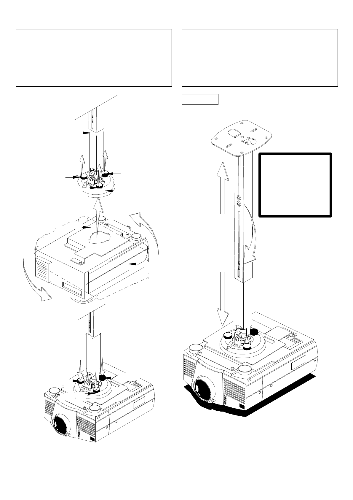
manuals.online logo
Brands
  1. Home
  2. •
  3. Brands
  4. •
  5. 3M
  6. •
  7. Projector Accessories
  8. •
  9. 3M HE100 User manual

3M HE100 User manual

This manual suits for next models

1

Other 3M Projector Accessories manuals

3M Wireless Network Module EP8790NET Manual

3M

3M Wireless Network Module EP8790NET Manual

3M SCP716W User manual

3M

3M SCP716W User manual

Popular Projector Accessories manuals by other brands

Optoma BX-AL133B datasheet

Optoma

Optoma BX-AL133B datasheet

PEERLESS PE 1120 Installation and assembly

PEERLESS

PEERLESS PE 1120 Installation and assembly

Osram SIRIUS HRI Series Directions for use

Osram

Osram SIRIUS HRI Series Directions for use

Presentation Switchers PS111 quick start

Presentation Switchers

Presentation Switchers PS111 quick start

Kramer VIA GO user manual

Kramer

Kramer VIA GO user manual

Yamaha PJL-112 Replacement guide

Yamaha

Yamaha PJL-112 Replacement guide

Mitsubishi Electric 236CB Features

Mitsubishi Electric

Mitsubishi Electric 236CB Features

Epson BrightLink 475Wi user guide

Epson

Epson BrightLink 475Wi user guide

Acer WP100 quick guide

Acer

Acer WP100 quick guide

i3 i3board user manual

i3

i3 i3board user manual

CHIEF HB-43E installation instructions

CHIEF

CHIEF HB-43E installation instructions

Biamp Modena Hub Network administrator's guide

Biamp

Biamp Modena Hub Network administrator's guide

NEC MP10RX Quick setup guide

NEC

NEC MP10RX Quick setup guide

Panamorph DCR-S3 installation guide

Panamorph

Panamorph DCR-S3 installation guide

Exact solutions FRAME-EVO-P10 manual

Exact solutions

Exact solutions FRAME-EVO-P10 manual

CHIEF VCM103S installation instructions

CHIEF

CHIEF VCM103S installation instructions

InFocus LP70+ Replacement instructions

InFocus

InFocus LP70+ Replacement instructions

Sharp AN-PH20EZ Operation manual

Sharp

Sharp AN-PH20EZ Operation manual

manuals.online logo
manuals.online logoBrands
  • About & Mission
  • Contact us
  • Privacy Policy
  • Terms and Conditions

Copyright 2025 Manuals.Online. All Rights Reserved.

1
MIDDLE EXTENSION
CEILING PLATE
BELL HOUSING
M8 HEX HEAD SCREW
FLAT WASHER
STAR WASHER
M8 HEX HEAD SCREW
FLAT WASHER
STAR WASHER
(REMOVE)
78-6969-9698-8 (White)
HE100® CEILING MOUNT SUSPENSION ADAPTOR
___________________________
3M Visual Systems Division
3M Austin Center
6801 River Place Blvd.
Austin Texas 78726-9000
The wall or ceiling structure must be capable of supporting at least five (5) times the weight of projector. If not, t
he wall or ceiling must be reinforced.
Proper installation procedure by qualified personnel as outlined in the installations instructions must be adhered to. Failure to do so could result in
serious personal injury
Step1
Remove the middleextension from the3M mount by removing two (2) of the M8 x 16 hex head
screws washers and star washers from the top and bottom holding the extension. See figure 1.
Figure 1
2
Step2
Replace themiddle extension with the 78-6969-9698-8with the same hardware that was
removed.
CEILING PLATE
BELL HOUSING
78
-
6969
-
9698
-
8
EXTENSION
M8 HEX HEAD SCREW
FLAT WASHER
STAR WASHER
M8HEXHEAD SCREW
FLAT WASHER
STAR WASHER
M8 HEX HEAD SCREW
FLAT WASHER
STAR WASHER
M8 HEX HEAD SCREW
FLAT WASHER
STAR WASHER
Figure 2
3
Step 3
SINGLE STUD:
Locate the center of the single wood stud in the ceiling or on the wall. Secure the
upper plate to the single stud using the three (3) #14 wood screws (supplied) with the3M mount
or use (commercially available) suitable hardware depending on your installation environment.
Start to secure the plate on the center
outer mounting points first. The plate may travel ½" front to
back from center of the slots for proper installation.See figure 3.
SOLID STRUCTURE: Choose the proper location for your mount. Secure the upper plate to the
solid structurebyusing the fourmounting points found on the ceiling
plate. Use suitable hardware
(commercially available) depending on the installation requirements. See figure 4.
SINGLE STUD INSTALLATION
SOLID STRUCTURE
INSTALLATION
Figure
3
Figure 4
SINGLE WOOD
STUD
CEILING STRUCTURE
CEILING PLATE
(3) #14 X 2"
WOOD SCREWS
78
-
6969
-
9
698
-
8
EXTENSION
SOLID STRUCTURE
CEILING
CEILING PLATE
78
-
6969
-
9698
-
8
EXTENSION
SUITABLE HARDWARE
(COMMERCIALLY AVAILABLE)
4
HEIGHT ADJUSTABLE
Step4
Fully raise the safety and tension knobs pick the projector with the mounting bracket
attached. Fully insert the arrow design opening from the mounting bracket to the
receiving tabs found on the bottom plate of the 78-6969-9698-8®. Once the bracket is
inserted, rotate the projector 180° and align the front arrow shaped slot from the
mounting bracket to the safety screw. The safety screw must go past the arrow shaped
slot below to prevent further rotation, finger tighten the rest of the tension screws to
stabilize the mounting bracket. Do not over-tighten the screws. See figure 5.
Step5
For grater heightadjustabilityor changing the remove the projector from the bell
housing, loosen the screws make your height adjustment or choose the lower slot.
Secure the height adjustment with the two(2) M8 Hex head screw.
CAUTION: For fine height adjustments hold the projector before loosening the
screws and adjusting.
Figure 5
WARNING
When making a height adjustment
while
the ceiling plate is secured to
the ceiling or wall.
Do not remove the screws
completely from the extension.
Loosen; adjust then re-tight the
screws. Failure to do so could
result in injury and damage to the
projector.
BELL HOUSING
SAFETY KNOB
78
-
6969
-
9698
-
8
EXTENSION
PROJECTOR
(NOT SUPPLIED)
MOUNTING BRACKET
RAISE THE
FINGER TIGHT
SAFETY KNOB
FINGER TIGHT
TENSION KNOBS
FINGER TIGHT
TENSION KNOBS
RAISE THE
TENSION KNOBS
RAISE THE
TENSION KNOBS
Figure 6