4EVAC Compact 500 User manual

Hacousto Holland bv
Industrieweg 87
2651BC Berkel & Rodenrijs
4EVAC Compact 500 quick guide
DoP OD 16.47
Author:
DD
Design revision:
2.0
Page 1of 33
SUMMARY
This document is the quick guide for installation and initial setup of Compact 500 Voice Evacuation System.
It explains how the hardware of Compact 500 should be installed and configured. Quick guide is addressed
to the trained technical personnel, such as installers, service technicians and commissioning engineers.
REVISION AND APPROVAL
Rev.
Date
Nature of Changes
Approved By
03
22-09-2017
Corrected audio performance specs
DD
04
25-03-2020
General update
AJH
05
04-06-2020
Corrections
TvdH

Hacousto Holland bv
Industrieweg 87
2651BC Berkel & Rodenrijs
4EVAC Compact 500 quick guide
DoP OD 16.47
Author:
DD
Design revision:
2.0
Page 2of 33
Table of Contents
1. What’s in the box?................................................................................................................................................................... 3
2. What else do I need to make it run? ................................................................................................................................ 3
3. Where do I start?..................................................................................................................................................................... 4
4. Unboxing 4EVAC Compact 500 ......................................................................................................................................... 4
5. Mounting Compact 500 onto a wall................................................................................................................................. 5
6. Installation.................................................................................................................................................................................. 6
Open the cabinet........................................................................................................................................................... 6
Mains.................................................................................................................................................................................. 8
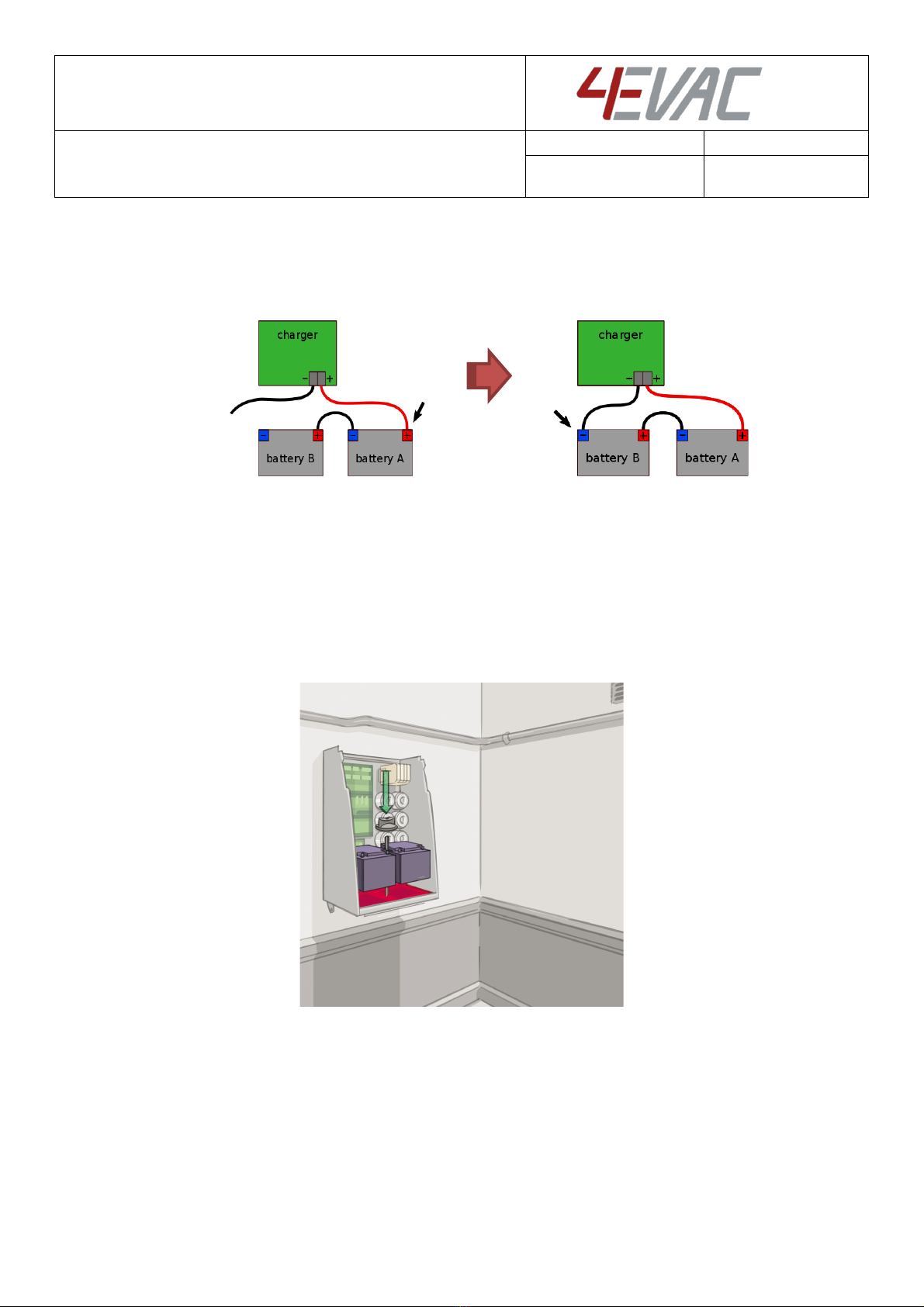
Battery ............................................................................................................................................................................... 8
EVAC / SILENCE / RESET inputs............................................................................................................................... 11
System status relay outputs ...................................................................................................................................... 11
6.5.1. EVAC out ...........................................................................................................................................................12
6.5.2.FAULT out .........................................................................................................................................................12
6.5.3.RESET out ..........................................................................................................................................................12
GPI / GPO ........................................................................................................................................................................12
Loudspeaker lines.........................................................................................................................................................13
6.7.1. Bridging to 200 W..........................................................................................................................................13
6.7.2. EOL board.........................................................................................................................................................16
Analog audio input (BGM) ........................................................................................................................................17
Network ports................................................................................................................................................................17
6.9.1. Global network (G-Net)................................................................................................................................18
6.9.2.Local network (L-Net) ..................................................................................................................................20
Memory card..................................................................................................................................................................21
Device ID setting..........................................................................................................................................................22
7. Startup and commissioning...............................................................................................................................................23
Power-on / power-off sequence............................................................................................................................23
Battery setting...............................................................................................................................................................23
Power supply equipment indications ...................................................................................................................25
Loudspeaker line impedance calibration ............................................................................................................26
Amplifer unit indications...........................................................................................................................................28
8. Connections and recommended cable types..............................................................................................................30
9. Technical specifications........................................................................................................................................................31

Hacousto Holland bv
Industrieweg 87
2651BC Berkel & Rodenrijs
4EVAC Compact 500 quick guide
DoP OD 16.47
Author:
DD
Design revision:
2.0
Page 3of 33
Thank you for choosing 4EVAC as your Voice Evacuation System solution.
4EVAC Compact 500 is all-in-one-box Voice Evacuation System. The box contains a completely integrated
Voice Evacuation System, capable of both standalone and network operation. 4EVAC Compact 500 is
certified in accordance to EN54-16 and EN54-4, which are harmonized standards under Construction
Products Regulation, mandatory in the European Union.
1. What’s in the box?
Inside the package you will find the main unit of Compact 500 Voice
Evacuation System, which includes:
Wall-mounted IP30 housing;
Integrated push-button panel and fireman microphone on the front;
Mainboard with input and output ports (including screw terminal
plugs);
Memory card (microSD);
DA200 dual-channel amplifier units incl. 100V step-up transformers
(number of amplifier units depends on the hardware config you
ordered);
DIN-rail with 16A fused manual mains switch;
Integrated EN54-4 power supply equipment with temperature-
compensated charger;
Battery leads set with; 20A battery fuse and battery terminal insulating caps;
Jumpers for amplifier units (if you’re planning to bridge amplifier outputs to 200W)
Before shipping, the hardware is pre-configured in our factory according to your project-specific
requirements. This includes:
Number of primary amplifier units (1, 2 or 3 units)
Optional backup amplifier (0 or 1 unit)
2. What else do I need to make it run?
4EVAC Compact 500 needs additional items, which you are responsible to supply on your own. The
additional equipment includes:
Battery,
Mains cord,
Wall mounting plugs (5 pieces, ø8mm),
10kΩ and 4.7kΩ resistors (for surveillance of EVAC triggering inputs, 1 pair per input);
EOL boards for surveillance of loudspeaker lines (available at 4EVAC in packs of 10 pieces);
Network cabling (if you are building network system),
Configuration file prepared in 4EVAC Manager PC software (software and GUI manual available at
4EVAC)

Hacousto Holland bv
Industrieweg 87
2651BC Berkel & Rodenrijs
4EVAC Compact 500 quick guide
DoP OD 16.47
Author:
DD
Design revision:
2.0
Page 4of 33
3. Where do I start?
First, make sure that you are officially allowed to access the Compact 500 hardware. This is usually the case
if:
you are an authorized representative of 4EVAC;
you have been trained by 4EVAC or its authorized representative for installation, service and
commissioning of the Compact 500 Voice Evacuation System.
Unauthorized hardware and/or software modifications are against the law and outside of manufacturer’s
responsibility. If you have doubts about your status and access level permissions, please contact the 4EVAC
main office.
Important note: Access level explanation
Opening the Compact 500 front door gives physical access to all
interfaces, internal system connections and sensitive hardware settings
that are of high importance to system operation mode, hardware
reliability and safety (Access Level 3 according to EN54-16, Annex A).
This access level (and higher) is strictly protected by the manufacturer
and reserved only for service personnel which is trained, approved and
officially certified by the manufacturer. Any actions carried out in
Access Level 3 without the manufacturer’s explicit approval may lead
to incorrect settings or hardware damage, causing serious system
malfunction, and therefore are strictly prohibited and void
manufacturer’s warranty.
4. Unboxing 4EVAC Compact 500
The original shipping package includes a bottom foam protector that allows you to place the main unit in
vertical position on the floor after unboxing.
Caution! Never put Compact 500 in a vertical position directly on the floor, table or any other hard
horizontal surface. Doing this may deform or break bottom parts of the housing.
Optionally, the cabinet may be temporarily placed on its back, on a flat horizontal surface.
To safely unbox the Compact 500 main unit, follow these steps:
1. Carefully cut the two strapping tapes and remove them.
Caution! Strapping tapes may be under very high tension!
2. Carefully put the package upside-down.
3. Open the bottom side and unfold the bottom panels of the package so that the bottom foam
protector is free from obstacles.
4. Carefully flip the package, first on its side and then right-side up.
5. Pull the carton package upwards and remove it.
6. Fold the protective foil down or remove it, leaving the Compact 500 main unit resting in the foam
protector until you’re ready to hang it on the wall.

Hacousto Holland bv
Industrieweg 87
2651BC Berkel & Rodenrijs
4EVAC Compact 500 quick guide
DoP OD 16.47
Author:
DD
Design revision:
2.0
Page 5of 33
5. Mounting Compact 500 onto a wall
The Compact 500 main unit is meant to be mounted on vertical structures, such as concrete walls.
NOTE: To provide sufficient ventilation, keep at least 20 cm space on both sides of the cabinet. Keep
ventilation grills free of obstacles!
At the back side of the Compact 500 cabinet you will find a wall-mount bracket provided with 3 fixing holes.
Note the two slots in the back plate of the cabinet, corresponding to the wall bracket hooks.
When the cabinet is mounted, there is a 10 mm space between the cabinet and the wall. This space can be
used for cables running from the floor to the top of cabinet.
Prepare wall-plugs and follow these steps:
1. Place the bracket on the wall. Optimal height of the top is 170 cm above floor level.
2. Using wall plugs, fix the bracket in 3 points.
3. Optionally, in the space between the left and right edge of the bracket, place cables flat on the
wall, vertically.
4. Lift the Compact 500 cabinet and place it flat against the wall:
a. The top of the cabinet should be at least 20 cm above the bracket top edge,
b. The side edges of the cabinet should be flat against the wall, hiding the bracket (and
cables) behind it.
5. Slide the cabinet down until it hangs on the bracket.
6. Check if the position of the cabinet is straight and all edges at the back are flush with the wall.
7. Check if the cabinet is placed firmly on the bracket and does not move in any direction.
8. Lock with two bottom wall plugs.
NOTE: The maximum weight of the main unit (without battery) is 29 kg. We strongly advise that the cabinet
should be lifted and hung by at least two persons. Check your local safety requirements on the maximum
allowed weight per person.

Hacousto Holland bv
Industrieweg 87
2651BC Berkel & Rodenrijs
4EVAC Compact 500 quick guide
DoP OD 16.47
Author:
DD
Design revision:
2.0
Page 6of 33
Caution! Never mount or un-mount the cabinet with battery inside!
6. Installation
Caution! Risk of electric shock! Keep the mains switch OFF or unplugged from the mains outlet during
the entire installation process. Do not install or uninstall any parts of the system while the mains voltage is
on.
Open the cabinet
In order to open the cabinet, follow the steps below:
1. Find two round openings in the front top part of the cabinet, where fixing screws are placed.
2. Undo both screws using a hex key (also known as Allen wrench or in-bus).
3. Hold both the left and right top corners of the front door.
4. Open the front door by pulling back the top of the front door. Try to pull both the left and right
side simultaneously with the same force.
5. Slowly keep opening the front door until it tilts 180°
6. Leave the front door hanging freely upside-down.
7. Inside the cabinet, locate the hinges on the left and right side of the backplate: Check if the cabinet
hangs properly on the wall bracket.

Hacousto Holland bv
Industrieweg 87
2651BC Berkel & Rodenrijs
4EVAC Compact 500 quick guide
DoP OD 16.47
Author:
DD
Design revision:
2.0
Page 7of 33
After opening the Compact 500, you should see following functional sections, as shown on the picture
below:
Compact 500 – inside main unit
Compact 500 - connection bay

Hacousto Holland bv
Industrieweg 87
2651BC Berkel & Rodenrijs
4EVAC Compact 500 quick guide
DoP OD 16.47
Author:
DD
Design revision:
2.0
Page 8of 33
Mains
Connect the 110 ~230V AC mains cable to input of the switch on the DIN rail in the top-right area. Keep
the right polarity and connect the ground wire to the ground terminal.
Caution! Be careful! Make sure that the mains cable is not connected to the electricity network during
installation.
Battery
NOTE: Place the battery only when the cabinet of Compact 500 is firmly fixed to the wall.
Install only sealed lead-acid batteries for stationary use. Compact 500 is designed to operate with 2 x 12V
batteries, each a maximum dimension of 230 x 138 x 207 mm (LxWxH).
To safely and properly install the battery circuit, follow the instruction below:
1. Before installing the battery, measure the voltage of each battery separately. Open-circuit voltage
of a well-functioning, healthy 12V battery should be in range of: 11,5 V – 13,5 V DC. If the open-
circuit battery voltage is out of this range, replace the battery. Always use pairs of batteries with
the same open-circuit voltage (as close as possible).
2. Adjust the battery bracket position to make enough room in the battery compartment (bottom of
the cabinet).
NOTE: If your batteries are large, it may be difficult to access the battery connector on the charger board.
In this case it’s best to connect battery leads to the connector on the charger board first, before putting
the battery into the cabinet.
Battery connector on the charger board.
1. Take the battery fuse out of the socket on the charger board! You will plug the fuse later, when
the system is running on mains supply.
2. Connect battery leads to the charger board.

Hacousto Holland bv
Industrieweg 87
2651BC Berkel & Rodenrijs
4EVAC Compact 500 quick guide
DoP OD 16.47
Author:
DD
Design revision:
2.0
Page 9of 33
3. Put the battery in the battery compartment.
4. Make sure that all battery leads are long enough and have rubber insulating caps on their ends.
Caution! Be careful! The negative pole of the battery connector is directly connected to ground potential
and the entire metal housing of Compact 500. Dropping an unprotected battery lead on any part of the
hardware, housing or battery brings high risk of a short-circuit and may damage the hardware and the
battery. The high electrical current from the battery under short-circuit condition may cause rapid battery
discharge and instant heat production. This may also destroy hardware components, cause serious battery
capacity degradation or battery damage, cause fire and may be a potential risk to your health.
5. Connect the battery jumper (short black) between the negative (-) pin of battery A and the positive
(+) pin of battery B.

Hacousto Holland bv
Industrieweg 87
2651BC Berkel & Rodenrijs
4EVAC Compact 500 quick guide
DoP OD 16.47
Author:
DD
Design revision:
2.0
Page 10 of 33
6. Connect the battery leads in order FROM (+) TO (-), as follows:
a. First, connect the (+) lead (long red) to the positive (+) pin of battery A;
b. Next, connect the (-) lead (long black) to the negative (-) pin of battery B;
7. Check the voltage of each battery again, separately, and the total voltage of both batteries.
8. Cover all battery terminals with insulating rubber caps.
9. Put the thermal sensor inside one of the rubber pads, so that it has good thermal contact with the
battery terminal.
10. Fasten the thermal sensor to the battery lead with a tie-wrap.
11. Secure the battery mechanically:
a. Fix the bottom bracket,
b. Twist the red plastic wing-nut hand-tight.

Hacousto Holland bv
Industrieweg 87
2651BC Berkel & Rodenrijs
4EVAC Compact 500 quick guide
DoP OD 16.47
Author:
DD
Design revision:
2.0
Page 11 of 33
EVAC / SILENCE / RESET inputs
There are 8 monitored inputs dedicated to triggering signals for evacuation, silence and reset instructions
from the external fire detection system.
6 x EVAC in
1 x SILENCE in
1 x RESET in
Each of these 2-pin inputs has built-in DC monitoring which requires two resistors of 4.7kΩ + 10kΩ in order
to detect an input active/inactive state as well as a short and open fault. EOL resistors must be located
directly at the triggering output inside of the external device (i.e. fire detection system) to provide reliable
surveillance of the entire link.
EVAC / SILENCE / RESET inputs must receive an activation signal of at least 100ms in order to trigger events.
Pulses shorter than 100ms will be ignored.
System status relay outputs
There are 3 potential-free relay outputs to external devices. Each output has individual 3 pins:
normally open,
normally closed,
common.

Hacousto Holland bv
Industrieweg 87
2651BC Berkel & Rodenrijs
4EVAC Compact 500 quick guide
DoP OD 16.47
Author:
DD
Design revision:
2.0
Page 12 of 33
6.5.1. EVAC out
Activated (closed) on EVAC mode, where at least one zone of the voice evacuation system is transmitting
an automatic EVAC message or LIVE EVAC signal from the fireman microphone.
6.5.2.FAULT out
Activated (closed) while the fault status is reported by the voice evacuation system.
Also activated when the Compact 500 is not powered.
6.5.3.RESET out
Activated (closed) immediately after a manual reboot of the Compact 500 main unit. The active pulse length
is configurable from 0 (disabled) to 5000ms in the configuration settings.
GPI / GPO
8 x general purpose input (pull-down), 8 x general purpose output (open collector)
GPIs and GPOs are programmable in the configuration file. The GPI and GPO can be linked to any system
events to trigger or follow system events.

Hacousto Holland bv
Industrieweg 87
2651BC Berkel & Rodenrijs
4EVAC Compact 500 quick guide
DoP OD 16.47
Author:
DD
Design revision:
2.0
Page 13 of 33
Loudspeaker lines
6 outputs to 100V loudspeaker lines (6 x 100W)
NOTE: Terminals BU1 and BU2 are not used.
6.7.1. Bridging to 200 W
Each amplifier unit in Compact 500 offers 2 audio channels, max. 100W each. By default both channels are
working independently, each with a 100V output.
Loads greater than 100W (up to 200W) are handled by bridging outputs of both channels of the amplifier
unit into one 200W channel. This is done by lowering the output voltage of both channels to 50V via output
voltage jumpers (bridging jumpers) and connecting two 50V output lines in series, at the loudspeaker line
connector.
Location of jumpers on the amplifier module

Hacousto Holland bv
Industrieweg 87
2651BC Berkel & Rodenrijs
4EVAC Compact 500 quick guide
DoP OD 16.47
Author:
DD
Design revision:
2.0
Page 14 of 33
6.7.1.1. Single channel
For single channel mode (2x100W), two jumpers on the amplifier unit must be set to the “100V” position
(center position). One jumper per channel.
Jumper setting 100V per channel – amplifier unit
Single channel: line 1, line 2 – loudspeaker line output

Hacousto Holland bv
Industrieweg 87
2651BC Berkel & Rodenrijs
4EVAC Compact 500 quick guide
DoP OD 16.47
Author:
DD
Design revision:
2.0
Page 15 of 33
6.7.1.2. Bridged
For bridged mode (1x200W), four jumpers must be set to the “50V” position (left & right position). Two
jumpers per channel.
Jumper setting 50V per channel – amplifier unit
Bridged lines: 3+4, 5+6 – loudspeaker line output

Hacousto Holland bv
Industrieweg 87
2651BC Berkel & Rodenrijs
4EVAC Compact 500 quick guide
DoP OD 16.47
Author:
DD
Design revision:
2.0
Page 16 of 33
6.7.2. EOL board
EOL boards are not supplied with the Compact 500 main unit and are available at 4EVAC as a separate
product.
4EVAC Compact 500 supports surveillance of loudspeaker lines based on a 20 kHz impedance
measurement.
For reliable impedance monitoring of the speaker line, use an EOL board. Connect the EOL board to the
end of the loudspeaker line in parallel, preferably inside the last loudspeaker on the line. The EOL is not
polarity-sensitive.
Loudspeaker line with EOL module
NOTE: The EOL module features a 145°C thermal fuse, minimizing the risk of a line short-circuit under fire
conditions. Exposing the EOL board to temperatures exceeding 145°C will damage the EOL circuit and
cause an open fault of the loudspeaker line.
The purpose of the EOL is to create a reference load at the monitoring frequency of 20kHz. With the EOL
connected, the monitoring of load impedance is more accurate and less sensitive to slow and long-term
impedance drift of the loudspeakers due to aging and weather conditions. It also gives more reliable fault
indication when a large number of loudspeakers is placed on one long line.
EOL board
NOTE: It is required to use an EOL module on every monitored loudspeaker line.
To optimally measure the loudspeaker line impedance, you can adjust the impedance of the EOL by
breaking out corners of the EOL PCB (using a tool, e.g. pliers or cutters). For the best result of impedance
measurements, use settings as described in the table below:
EOL load setting
EOL impedance @20kHz
Normal - tip on (factory original)
320 Ω
Light - tip off
640 Ω

Hacousto Holland bv
Industrieweg 87
2651BC Berkel & Rodenrijs
4EVAC Compact 500 quick guide
DoP OD 16.47
Author:
DD
Design revision:
2.0
Page 17 of 33
Analog audio input (BGM)
Two analog audio inputs, balanced, line-level.
Connect your auxiliary audio source for background music or low a priority external paging microphone
here.
NOTE: By default, the Compact 500 includes an integrated fireman microphone, which occupies analog
audio input 2. If your system does not require an integrated fireman microphone feature, you can disable
it in the configuration settings and use analog audio input 2 as an external audio input for background
music.
Network ports
4EVAC Compact 500 offers 5 ports (RJ-45) for network connections between distributed parts of the 4EVAC
Voice Evacuation System:
2 x G-Net ports (global network)
3 x L-Net ports (local network)
The 4EVAC network features a full duplex RS-422 data link and 24V DC power to remote devices.
If you’re building a distributed system using the 4EVAC network, you should make physical links between
devices using the right cables. Cabling should meet the following requirements:
1. Crossover twisted-pair cable (compatible with Ethernet crossover)

Hacousto Holland bv
Industrieweg 87
2651BC Berkel & Rodenrijs
4EVAC Compact 500 quick guide
DoP OD 16.47
Author:
DD
Design revision:
2.0
Page 18 of 33
2. CAT5e or higher for maximum distance of 250m.
3. Non-CAT / lower than CAT5e: 250m not guaranteed.
4. Shield required (at least FTP)
Caution! Use only crossover cables and keep the correct pinout! Connecting power pins to data pins will
damage the network port.
6.9.1. Global network (G-Net)
G-Net works as a redundant ring between Compact 500 main units. It is dedicated to secure a reliable
system bus, which keeps the global system intact in case of single link failure.
pin number pin number
GND shield shield GND
RX+ 1 1 RX+
RX- 2 2 RX-
TX+ 3 3 TX+
power + 4 4 power +
power - 5 5 power -
TX- 6 6 TX-
power + 7 7 power +
power - 8 8 power -
pin number pin number
GND shield shield GND
RX+ 1 1 RX+
RX- 2 2 RX-
TX+ 3 3 TX+
power + 4 4 power +
power - 5 5 power -
TX- 6 6 TX-
power + 7 7 power +
power - 8 8 power -
xover type A cable
xover type B cable

Hacousto Holland bv
Industrieweg 87
2651BC Berkel & Rodenrijs
4EVAC Compact 500 quick guide
DoP OD 16.47
Author:
DD
Design revision:
2.0
Page 19 of 33
To create a redundant G-Net ring between multiple Compact 500 main units, connect both G-Net ports
between every unit in the network, so that you create a closed ring.
G-Net redundant ring topology
Power over G-Net
Both G-Net ports have individual settings for 24V DC power over G-Net for remote G-Net devices. Power
over G-Net is set by means of hardware jumpers located next to the G-Net port.
Power over G-Net is dedicated to supply devices connected to the G-net port, such as fiber transceivers.
Location of G-Net 24V power jumpers
By default, power over G-Net is off.
jumpers in the LEFT position:
24V DC power ON
jumpers in the RIGH position (or no jumper):
24V DC power OFF
NOTE: If you connect G-Net directly between Compact 500 main units, please leave the power jumpers in
the OFF position.

Hacousto Holland bv
Industrieweg 87
2651BC Berkel & Rodenrijs
4EVAC Compact 500 quick guide
DoP OD 16.47
Author:
DD
Design revision:
2.0
Page 20 of 33
6.9.2.Local network (L-Net)
L-Net works as a daisy-chain bus between the Compact 500 main unit and remote network devices, such
as paging consoles. It is dedicated to provide a powered bus to peripheral devices. Every L-Net port is
powered with 24V DC and power over L-Net is always enabled.
L-Net capacity of single a Compact 500 unit is limited to the following figures:
Maximum 8 devices per port,
Maximum 16 devices per Compact 500 main unit.
L-Net daisy chain topology
For more information about installation of remote network devices, please go to the network device
installation manual.
Other manuals for Compact 500
1
Table of contents
Other 4EVAC Safety Equipment manuals
Popular Safety Equipment manuals by other brands

MSA
MSA SURETYMAN SRS15 Application, Operation, Maintenance & Inspection Instructions Manual

ABS
ABS B-Lock manual

KStrong
KStrong AFL405101 User instruction manual

E2S
E2S STExCP8-BG-S instruction manual

Crewsaver
Crewsaver VOYAGER 275N Service manual

Saxby Lighting
Saxby Lighting Sight Plus 94346 instruction manual