4EVAC Compact 500 User manual

Hacousto Holland bv
Industrieweg 87
2651BC Berkel & Rodenrijs
4EVAC Compact 500 operation manual
Author:
DD
Page 1of 15
SUMMARY
This document is the operation manual for users of the Compact 500 Voice Evacuation System. It explains
how to operate the Compact 500 and how to interpret indications. This operation manual is addressed to
end users as well as technical personnel, such as service technicians.
REVISION AND APPROVAL
Rev.
Date
Nature of Changes
Approved By
02
05-07-2017
Minor corrections, typos
DD
03
14-01-2018
Backup amp test, bandwidth update
DD
04
04-06-2020
Corrections
TvdH

Hacousto Holland bv
Industrieweg 87
2651BC Berkel & Rodenrijs
4EVAC Compact 500 operation manual
Author:
DD
Page 2of 15
Table of Contents
1. What does Compact 500 do? ............................................................................................................................................. 3
2. Configuration settings ........................................................................................................................................................... 3
3. Standalone vs network operation...................................................................................................................................... 4
Standalone system........................................................................................................................................................ 4
Network system.............................................................................................................................................................. 4
3.2.1. Global network (G-Net)................................................................................................................................. 4
3.2.2.Local network (L-Net) .................................................................................................................................... 5
4. Front Panel................................................................................................................................................................................. 6
LED indicators ................................................................................................................................................................. 6
4.1.1. POWER................................................................................................................................................................ 6
4.1.2. EVAC .................................................................................................................................................................... 6
4.1.3. FAULT ...................................................................................................................................................................7
4.1.4. POWER SUPPLY ................................................................................................................................................7
4.1.5. SYSTEM FAULT ..................................................................................................................................................7
4.1.6. NETWORK ...........................................................................................................................................................7
4.1.7. Zone indicators ................................................................................................................................................ 8
Manual controls ............................................................................................................................................................. 9
4.2.1. SILENCE............................................................................................................................................................... 9
4.2.2.LAMP TEST......................................................................................................................................................... 9
4.2.3.ZONE selection................................................................................................................................................. 9
4.2.4.RESET................................................................................................................................................................... 9
4.2.5.FUNCTION button........................................................................................................................................... 9
5. Integrated fireman mic.........................................................................................................................................................10
6. KEY switch .................................................................................................................................................................................10
7. Technical specifications........................................................................................................................................................ 11
8. Marking......................................................................................................................................................................................13

Hacousto Holland bv
Industrieweg 87
2651BC Berkel & Rodenrijs
4EVAC Compact 500 operation manual
Author:
DD
Page 3of 15
Thank you for choosing 4EVAC as your Voice Evacuation System solution.
4EVAC Compact 500 is all-in-one Voice Evacuation System box. The box contains a completely integrated
Voice Evacuation System, capable of both standalone and network operation. 4EVAC Compact 500 is
certified in accordance with EN54-16 and EN54-4, which are harmonized standards under Construction
Products Regulation, mandatory in the European Union.
1. What does Compact 500 do?
Compact 500 is a small form factor Voice Evacuation System which covers full compliance with standards
for voice alarm installations, offering features typical for public-address applications at the same time.
The primary task of the Compact 500 is to deliver reliable and intelligible transmission of voice alarm
messages to the public in emergency situations, such as fire. The secondary task of the Compact 500 is to
provide public-address functionalities, such as background music, public announcements or general
paging.
Compact 500 is extremely scalable due to its network capabilities and creates a distributed architecture
where each unit remains fully operational, even during network failure.
2. Configuration settings
Compact 500 is supplied with a pre-installed micro SD memory card. The memory card contains a complete
Compact 500 system configuration file, including audio messages.
The configuration file includes user-defined settings, such as:
-network components,
-zoning,
-audio message files ,
-volume levels,
-hardware related settings,
-system behavior for various triggers, etc.
The configuration file should be prepared in the C500 Manager. The 4EVAC Manager is a GUI software
package running on Windows OS. More information about the C500 Manager can be found in the software
manual “C500 Manager guide”.
NOTE: Please make sure that the configuration file is prepared with the version of the C500 Manager
compatible with the firmware of the Compact 500.
The installation file of the latest 4EVAC Manager and the manual are available at our website:
www.4EVAC.com

Hacousto Holland bv
Industrieweg 87
2651BC Berkel & Rodenrijs
4EVAC Compact 500 operation manual
Author:
DD
Page 4of 15
3. Standalone vs network operation
4EVAC Compact 500 is capable of both standalone and network operation.
Standalone system
A standalone Compact 500 comprises of a single C500 main unit, which incorporates:
Mandatory indications and manual controls
System status outputs: EVAC, FAULT, RESET
6 monitored EVAC inputs
Monitored SILENCE and RESET input
8 x GPI
8 x GPO
Up to 6 loudspeaker lines with EOL monitoring
100W or 200W maximum power per line
2 analog balanced audio inputs
Integrated Fireman Microphone with priority
Access key-lock to enable/disable front panel functionality
6 programmable zone selection buttons
Integrated power supply with battery
Network system
3.2.1. Global network (G-Net)
G-Net is a redundant network ring where multiple C500 main units may be connected into one system. It
is used for reliable data synchronization between all connected devices and for multi-channel live audio
transmission with very low latency.
G-Net redundant ring topology

Hacousto Holland bv
Industrieweg 87
2651BC Berkel & Rodenrijs
4EVAC Compact 500 operation manual
Author:
DD
Page 5of 15
3.2.2.Local network (L-Net)
L-Net daisy-chain topology is dedicated for peripheral devices of the main unit, such as remote microphone
stations. L-Net is used to expand C500 functionality to remote locations.
L-Net daisy chain topology

Hacousto Holland bv
Industrieweg 87
2651BC Berkel & Rodenrijs
4EVAC Compact 500 operation manual
Author:
DD
Page 6of 15
4. Front Panel
Compact 500 front panel
LED indicators
4.1.1. POWER
Indicates the operating status of the C500.
Continuous: system is powered and ready
Blinking fast: system is booting, not ready for full operation
4.1.2. EVAC
Indicates that the system is in the Voice Alarm state, where at least one zone in the system is occupied by
an emergency audio signal, i.e. a pre-recorded EVAC MESSAGE or LIVE EVAC, when a fireman mic is being
used.
Continuous: EVAC state

Hacousto Holland bv
Industrieweg 87
2651BC Berkel & Rodenrijs
4EVAC Compact 500 operation manual
Author:
DD
Page 7of 15
4.1.3. FAULT
Indicates that the system is in the FAULT state (general fault indicator), where at least one device in the
system is reporting a fault.
Continuous: when a local fault is detected
Blinking slow: when a local device is healthy and at least one remote device is reporting fault state
4.1.4. POWER SUPPLY
Indicates a power supply fault of the local C500 unit, where at least one of following faults is reported:
Continuous: mains fault
Blinking slow: battery-related fault:
oLoss of battery
oLoss of charger
oBattery resistance too high
oTemperature fault
oCharger communication fault
4.1.5. SYSTEM FAULT
Indicates system fault of the C500 main unit, where:
- The CPU or program execution is stopped or malfunctioning,
- Corruption of storage memory containing config settings and audio files (SD card).
- Front panel is not communicating with main board
Where a system fault is caused by a CPU or memory fault, the C500 remains in “safe state”, where critical
functions (including audio transmission, reaction on control inputs, etc.) are stopped until the fault
is removed.
Continuous:
oCPU / program fault
ofront panel fault
Blinking slow:
oSD card fault
oConfig file not compatible
oWrong ID setting
4.1.6. NETWORK
Indicates when any device or link in the network is missing.
Blinking slow:
Global ring is broken (any place in the ring)

Hacousto Holland bv
Industrieweg 87
2651BC Berkel & Rodenrijs
4EVAC Compact 500 operation manual
Author:
DD
Page 8of 15
Continuous:
At least one device from the network is missing.
4.1.7. Zone indicators
Zone indicators are strictly related to the corresponding zone button. If a button is not attached to any
zone, then zone indicators for this button are disabled.
Manual zone control
4.1.7.1. Red
Indicates that the zone is in EVAC condition, where the zone is occupied by one of following audio signals:
Continuous: LIVE EVAC
Blinking slow: EVAC Message.
4.1.7.2. Yellow
Indicates that the zone is transmitting an ALERT message, and/or is in fault state
Continuous: Zone fault (fault of any line / amplifier included in this zone)
Blinking slow: Zone is transmitting ALERT Message.
4.1.7.3. Blue
Zone busy / zone selection.
Continuous: indicates that the zone is manually selected via zone selection button on local panel
Blinking fast: the zone is occupied by audio signal, but is in SILENCE mode (triggered by SILENCE
input or manual SILENCE button)
Blinking slow: indicates that the zone is currently transmitting an audio signal (except BGM).
Zone A

Hacousto Holland bv
Industrieweg 87
2651BC Berkel & Rodenrijs
4EVAC Compact 500 operation manual
Author:
DD
Page 9of 15
Manual controls
4.2.1. SILENCE
Press to mute the sound of the buzzer in the entire system.
4.2.2.LAMP TEST
Press to verify visual (LEDs) and audible indications (buzzer) of the front panel of local C500.
4.2.3.ZONE selection
Press to select a zone. Press again to deselect.
NOTE: Zone selection will clear automatically after timeout defined in the configuration settings.
4.2.4.RESET
Press to clear your current zone selection.
4.2.5.FUNCTION button
Press and hold the FUNCTION button to enable Access level 2. In access level 2 you are able to manually
change the status of the system by triggering voice alarm message or resetting the system.
NOTE: Press FUNCTION button first and hold it down while pressing another button.
4.2.5.1. FUNCTION + EVAC / FUNCTION + ALERT
Use this combination in order to trigger the EVAC or ALERT message on the previously selected zones.
If no zones are selected, this will trigger EVAC or ALERT to all zones accessible from local front panel.
Triggering manual EVAC

Hacousto Holland bv
Industrieweg 87
2651BC Berkel & Rodenrijs
4EVAC Compact 500 operation manual
Author:
DD
Page 10 of 15
4.2.5.2. FUNCTION + SILENCE
Use this combination to trigger the silence instruction to the previously selected zones. If no zones are
selected, this silences on all zones accessible from local front panel.
NOTE: If any EVAC input is active during manual zone silence the activation trigger will override SILENCE
mode.
4.2.5.3. FUNCTION + RESET
Use this combination to reset the Compact 500 system. In a network system this will reboot the entire
network. If the reset was triggered successfully, all local LED indicators should start a fast-blinking sequence
during reboot.
4.2.5.4. FUNCTION + LAMP TEST
Use this combination to trigger the backup amplifier test. This test sequence will simulate an amplifier fault
for each local amplifier channel, one by one, forcing the backup amplifier to engage and take over the
channel where the fault is simulated. The sequence will be displayed on the front panel ZONE LEDs.
NOTE: the backup amplifier test can be triggered only if C500 has backup amplifier enabled.
5. Integrated fireman mic
The front panel of the C500 is equipped with a Fireman Microphone. Take out the handheld microphone
and press the PTT button and enable LIVE EVAC signal transmission to all zones available on the local panel.
This signal is a top priority audio stream and will override any other type of audio signal in the system.
If any zone was previously selected, you will start transmitting to selected zones only.
6. KEY switch
The C500 may be optionally equipped with a security key-switch on the front panel.
The key switch disables/enables the FUNCTION button and the PTT button of the fireman mic. Thus the
access level is protected with an additional step.
The key switch is under surveillance, so in case of electrical or mechanical failure, the key switch fault is
reported,

Hacousto Holland bv
Industrieweg 87
2651BC Berkel & Rodenrijs
4EVAC Compact 500 operation manual
Author:
DD
Page 11 of 15
7. Technical specifications
Standalone system
Number of zones
max. 6 local zones
Maximum total loudspeaker load
600 W RMS (420W RMS pure sinewave according to EN54-16)
Power amplifiers
6 x 100 W, modular (2 channels per module), bridgeable up to 3 x 200 W
Standby power amplifiers
2 x 100 W / 1 x 200 W dedicated backup amplifiers
Loudspeaker line monitoring
Built-in
20kHz AC monitoring with EOL module, short/open/impedance deviation
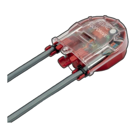
Loopdrive
loop DC monitoring with short-circuit isolators, short/open/earth leakage, EN54-
17 certified
Loudspeaker type
with 100V step-down transformer
Voice messages
Storage
max. 16 audio files x 1 minute each, micro-SD card with content monitoring
Message player
Max. 2 simultaneous local message playback
Controls and indications
General controls / indications
Lamp test button, silence button, power, evac, general fault LED indicators
Fault indications
Power supply, system fault, network, zone fault
Zone controls / indications
6 x configurable zone selection button, zone EVAC/FAULT/BUSY LED indicators
Evac manual control
EVAC message, ALERT message, SILENCE, RESET, fireman mic with PTT button
Fireman microphone
Integrated Fireman Mic with priority and electrical monitoring
Power supply equipment
Built-in power supply system, EN 54-4 certified.
AC supply
110 – 230 V AC, 50/60Hz
AC current consumption
max. 5.3A @115V AC / 2.65A @230V AC
Inrush current
20A @115V AC, 40A @230V AC
Power supply protection
Overload current limiting, over voltage shutdown, over temperature shutdown.
Battery requirements
Type
Sealed, rechargeable lead-acid battery for stationary use
Capacity
10 – 55 Ah
Charging time (80% capacity)
< 24 h
Rated voltage
24 V DC (2 x 12V)
Battery dimensions
2 batteries, each of max. 230 x 138 x 207 mm (LxWxH)
Battery weight
max. total 32.6 kg
Inputs
2 x BGM
2 x independent balanced analogue in, line-level mono, 22kΩ input impedance
6x EVAC in, 1x SILENCE in, 1x RESET in
monitored logic inputs, 4.7kΩ +10kΩ EOL resistors
8 x GPI
unmonitored logic inputs (pull-down, configurable active low/hi)
Outputs
EVAC out, FAULT out
Potential-free relay output (configurable NO/NC)
GPO
8 x Open collector output (configurable NO/NC)
Loudspeaker out
6 x 100V transformer output, 20 kHz AC monitoring with EOL
Amplifiers
Type
Class D
Protection
over load shutdown, over temperature shutdown
Backup amplifiers
2 dedicated backup channels, auto backup at end stage failure, auto restore
Efficiency
80% @ rated power
Output voltage
max. 100V RMS

Hacousto Holland bv
Industrieweg 87
2651BC Berkel & Rodenrijs
4EVAC Compact 500 operation manual
Author:
DD
Page 12 of 15
All information provided in this document is subject to change without notice. 4EVAC may also make improvements and/or changes
in the products described in this information at any time without notice.
Rated power
100W per channel, 200W bridged
Output bandwidth
50 Hz – 20 kHz
SNR
>80 dB
THD + N
0.1% @ rated power
Audio
Frequency response
Local BGM
50 Hz – 20 kHz
Messages, network streaming
100 Hz – 12 kHz
Analog input- output latency
< 10 ms (stand-alone system)
Network audio stream format
24 kHz sampling, ADPCM compressed
Message file input format
24 kHz, 16 bit, mono WAV
DSP features
HP/LP filter, multipoint parametric EQ, delay
Mechanical
Dimensions (HxWxD)
80 x 52 x 28 cm
Weight (full config, without batteries)
29 kg
Housing material
Steel / ABS
IP rating
IP 30
Mounting
Wall-mounted box
Network system
Max. number of devices in the network
255
Max. number of zones
255
Max. total system output power
102 kW
Number of simultaneous network audio channels
2
Network audio transmission latency
0.3 ms per device
Local network
Architecture
Master-slave, up to 16 slave devices per C500 main unit
Connection
3 x L-Net port, RJ-45, powered daisy chain, digital audio & control data
Cabling
X-over FTP CAT5e (or higher)
Current consumption
max. 500 mA (up to 8 slave devices) per L-Net port,
Max. length of local bus
default
250 m
with twisted-pair extender
500 m
Global network
Architecture
Peer-to-peer, up to 255 C500 main units
Connection
2 x G-Net port, RJ-45, powered redundant ring, digital audio & control data
Cabling
X-over FTP CAT5e (or higher) / multimode optical fiber
Current consumption
max. 500 mA per port, reserved only for network extenders
Max. distance between devices
default
250 m
with copper extenders
750 m
with fiber extenders
2500 m

Hacousto Holland bv
Industrieweg 87
2651BC Berkel & Rodenrijs
4EVAC Compact 500 operation manual
Author:
DD
Page 13 of 15
8. Marking

Hacousto Holland bv
Industrieweg 87
2651BC Berkel & Rodenrijs
4EVAC Compact 500 operation manual
Author:
DD
Page 14 of 15

Hacousto Holland bv
Industrieweg 87
2651BC Berkel & Rodenrijs
4EVAC Compact 500 operation manual
Author:
DD
Page 15 of 15
MADE IN THE NETHERLANDS
4EVAC is a trade name of:
Hacousto Holland bv
Industrieweg 87
2651BC Berkel & Rodenrijs
The Netherlands
www.4EVAC.com
Other manuals for Compact 500
1
This manual suits for next models
5
Table of contents
Other 4EVAC Safety Equipment manuals
Popular Safety Equipment manuals by other brands

DBI SALA
DBI SALA Nano-Lock 3101614 instruction manual

Kortel Design
Kortel Design KONCEPT user manual

Federal Signal Corporation
Federal Signal Corporation QuadraFlare DOT Installation and service instructions

Sordin
Sordin left/RIGHT Active FM Pro Product description

Ultra-safe
Ultra-safe M2-HPSY8Y User instruction manual

Simply Brands
Simply Brands RATCHET TIE DOWN instruction manual