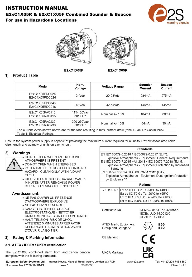
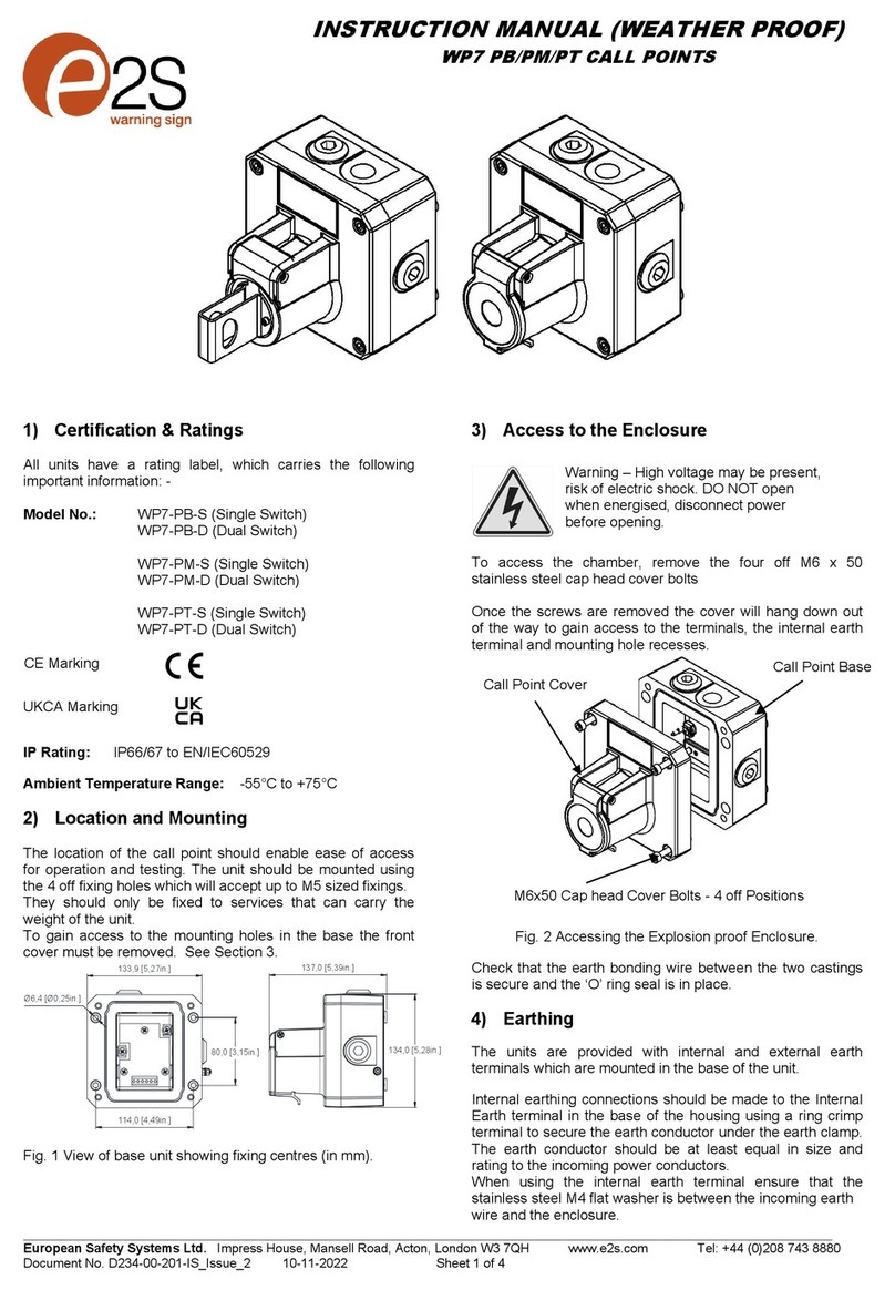
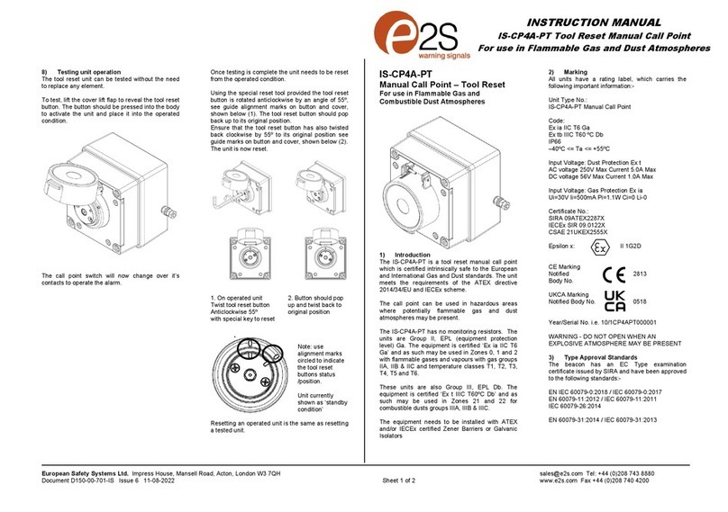
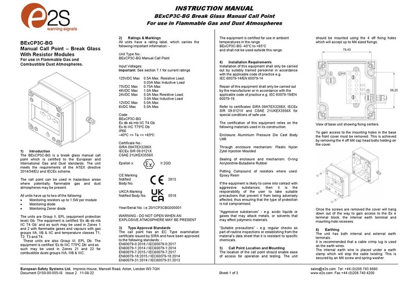
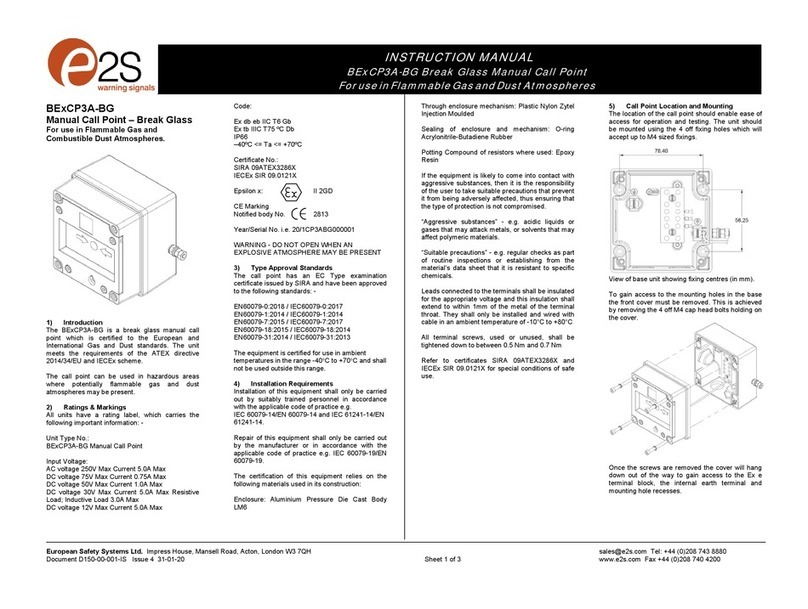
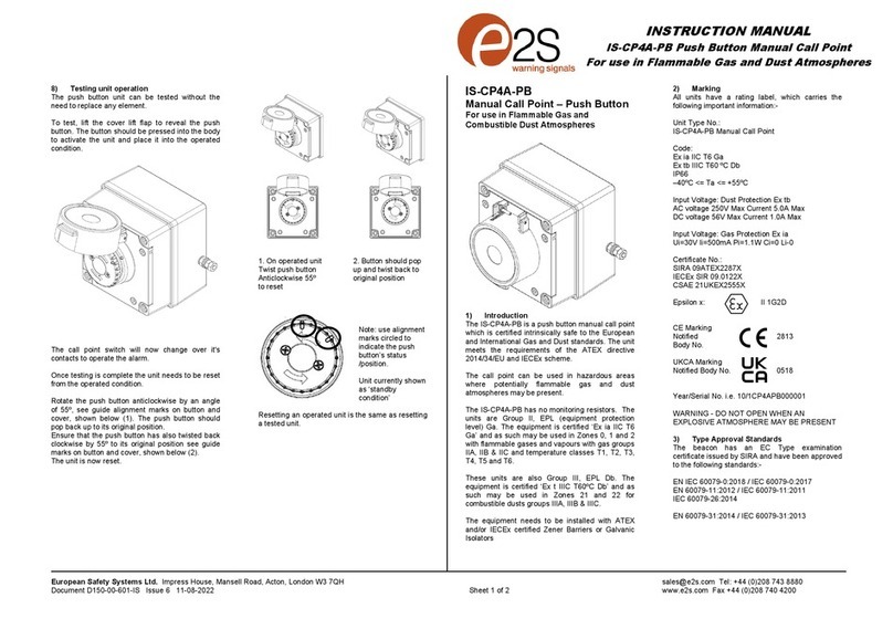
E2S STExCP8-BG-S User manual

_______________________________________________________________________________________________________________________________
European Safety Systems Ltd. Impress House, Mansell Road, Acton, London W3 7QH www.e2s.com Tel: +44 (0)208 743 8880
Document No. D204-00-001-IS Issue 7 16-12-2022 Sheet 1 of 6
Warnings
USE COVER BOLTS CLASS A4-70
DO NOT OPEN WHEN AN EXPLOSIVE
ATMOSPHERE IS PRESENT
POTENTIAL ELECTROSTATIC HAZARD
ALL ENTRIES M20 X 1.5
DO NOT OPEN WHEN ENERGIZED
IF TEMPERATURE EXCEEDS 70°C AT
ENTRY OR 80°C AT BRANCHING POINT
USE SUITABLE RATED CABLE AND CABLE
GLANDS
1) Rating & Marking Information
2.1 ATEX / IECEx / UKEX Certification
All units have a rating label, which carries the following
important information:
Model No.: STExCP8-BG-S (Single Switch)
STExCP8-BG-D (Dual Switch)
Input Voltage: DC Units 48Vdc Max
AC Units 250Vac max (units without
series or end-of-line devices only)
STExCP8-BG-S Codes:
Ex db IIC T6 Gb Ta. -55°C to +70°C
STExCP8-BG-D Codes:
Ex db IIC T5 Gb Ta. -55°C to +70°C
Ex db IIC T6 Gb Ta. -55°C to +60°C
Certificate No. DEMKO 15 ATEX 1589X
IECEx ULD 15.0018X
UL21UKEX2133X
UKCA Marking
Notified Body No.
The units can be installed in locations with the following
conditions:
Area Classification Gas:
Zone 1 Explosive gas air mixture likely to occur in
normal operation.
Zone 2
Explosive gas atmosphere not likely to
occur in normal operation but may be
present for short periods.
Gas Groupings:
Group IIA Propane
Group IIB Ethylene
Group IIC Hydrogen and Acetylene
Temperature Classification:
T1 450ºC
T2 300ºC
T3 200ºC
T4 135ºC
T5 100ºC
T6 85ºC (For Dual Switch models only up to
Tamb 60°C)
IP Rating: IP66/67 to EN/IEC60529 and IP6X to
EN/IEC60079-0, EN/IEC60079-31
Equipment Category: 2G
Equipment Protection Level: Gb
Ambient Temperature Range:
-55°C to +70°C Gas Groups IIA, IIB and IIC
2.2 DNV GL Type Approval
The units have been tested and approved for the installation
on ships in the following locations:
Temperature: Class A,B,C & D (all locations including
open decks and masts)
Humidity: Class A & B (all locations)
Vibration: Class A (all locations except installation on
machinery such as combustion engines,
compressors, pumps, including piping on
such machinery)
2813
II 2G
ATEX Marking
Equipment Group and
Category:
CE Marking
Notified Body No.
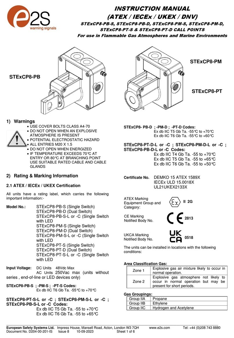
INSTRUCTION MANUAL
(ATEX / IECEx / UKEX / DNV GL)
STExCP8-BG-S & STExCP8-BG-D CALL POINT
For use in Flammable Gas Atmospheres and Marine Environments
STExCP8-BG
0518

_______________________________________________________________________________________________________________________________
European Safety Systems Ltd. Impress House, Mansell Road, Acton, London W3 7QH www.e2s.com Tel: +44 (0)208 743 8880
Document No. D204-00-001-IS Issue 7 16-12-2022 Sheet 2 of 6
EMC: Class A & B (all locations including open
decks and bridge)
Enclosure: Class A, B & C – IP56 (all locations except
submerged applications and bilges)
3) Type Approval Standards
The beacon carries an EC Type Examination Certificate and
IECEx Certificate of Conformity, and have been certified to
comply with the following standards:
EN60079-0:2012+A11:2013 / IEC60079-0:2011 (Ed 6):
Explosive Atmospheres - Equipment. General requirements
EN60079-1:2014 / IEC60079-1:2014 (Ed 7):
Explosive Atmospheres - Equipment protection by flameproof
enclosures "d"
4) Installation Requirements
The beacon must only be installed by suitably qualified
personnel in accordance with the latest issues of the relevant
standards:
EN60079-14 / IEC60079-14: Explosive atmospheres -
Electrical installations design, selection and erection
EN60079-10-1 / IEC60079-10-1: Explosive atmospheres -
Classification of areas. Explosive gas atmospheres
The installation of the beacon must also be in accordance
with any local codes that may apply and should only be
carried out by a competent electrical engineer who has the
necessary training.
The equipment must not be installed with any obstruction to
the flanged flameproof joint any closer than permitted as per
EN/IEC60079-14, table 13.
5) Special Conditions of Use
On completion of the installation the flameproof joint surfaces
should be inspected to ensure that they are clean and that
they have not been damaged during installation. Flameproof
joints are not permitted to be repaired.
When fitting the flameproof cover ensure the cover is sitting
flat and correctly positioned on the base. Insert the M6 x 40
cover bolts and fully tighten down (tightening torque 8.8Nm),
ensuring no gap is visible between the cover and base of the
enclosure.
The metallic enclosure has a non-conductive coating. These
may generate an ignition-capable level of electrostatic
charges under certain extreme conditions. The user should
ensure that the equipment is not installed in a location where
it may be subjected to external conditions that might cause a
build-up of electrostatic charges on non-conducting surfaces.
Additionally, cleaning of the equipment should be done only
with a damp cloth.
The M12 Cap fitted to the top side of the unit is not a user
serviceable part and must not be removed during installation
and maintenance.
6) Location and Mounting
The location of the call point should enable ease of access
for operation and testing. The unit should be mounted using
the 4 off fixing holes which will accept up to M5 sized fixings.
They should only be fixed to services that can carry the
weight of the unit.
To gain access to the mounting holes in the base the front
cover must be removed. See Section 7.
Fig. 1 View of base unit showing fixing centres (in mm).
7) Access to the Flameproof Enclosure
To access the Ex d chamber, remove the four off M6 x 40
hexagon socket head screws and withdraw the flameproof
cover taking extreme care not to damage the flameproof
faces in the process. M6 cover screws are Class A4-70
stainless steel and only screws of this category can be used
for the enclosure.
On completion of the installation, the flameproof joints should
be inspected to ensure that they are clean and that they have
not been damaged during installation.
Once the screws are removed the cover will hang down out
of the way to gain access to the terminals, the internal earth
terminal and mounting hole recesses.
Warning – Hot surfaces. External
surfaces and internal components may
be hot after operation, take care when
handling the equipment.
Warning – High voltage may be
present, risk of electric shock. DO NOT
open when energised, disconnect
power before opening.

_______________________________________________________________________________________________________________________________
European Safety Systems Ltd. Impress House, Mansell Road, Acton, London W3 7QH www.e2s.com Tel: +44 (0)208 743 8880
Document No. D204-00-001-IS Issue 7 16-12-2022 Sheet 3 of 6
Call Point Cover Call Point Base
M6x40 Cap head Cover Bolts - 4 off Positions
Fig. 2 Accessing the Explosion proof Enclosure.
Check that the earth bonding wire between the two castings
is secure and the ‘O’ ring seal is in place. When replacing the
flameproof cover casting ensure that it is square with the
flameproof chamber casting before inserting. Carefully place
the cover on the base. Only after the cover is fully in place
should the four M6 Stainless Steel A4-70 cover bolts and
their spring washer be tightened down. Never use the cover
bolts to force the cover into position.
8) Earthing
The units are provided with internal and external earth
terminals which are mounted in the base of the unit.
Internal earthing connections should be made to the Internal
Earth terminal in the base of the housing using a ring crimp
terminal to secure the earth conductor under the earth clamp.
The earth conductor should be at least equal in size and
rating to the incoming power conductors.
When using the internal earth terminal ensure that the
stainless steel M4 flat washer is between the incoming earth
wire and the enclosure.
External earthing connections should be made to the M5
earth stud, using a ring crimp terminal to secure the earth
conductor to the earth stud. The external earth conductor
should be at least 4mm2 in size.
External Earth
M5 Terminal
Internal Earth
Terminal
Wiring terminal Fig 3 Earth terminals
9) Power Supply Selection
Electrical Ratings
250Vac max. / 5.0A max
48Vdc max. / 1.0A max
24Vdc max / 3.0A max
A supply voltage variation of +/-10% outside the voltage
range is permissible.
Electrical connections are to be made into the terminal blocks
/ DIN rail provided.
10) Selection of Cable. Cable Glands, Blanking
Elements & Adapters
For high ambient temperatures the cable entry temperature
may exceed +70ºC or the cable branching point temperature
may exceed 80ºC and therefore suitable heat resisting cables
and cable glands must be used, with a rated service
temperature of at least the values stated below:
For Single Switch models STExCP8-BG-S:
For Dual Switch models STExCP8-BG:
The cable gland entries have an M20 x 1.5 entry thread. Only
suitably rated and ATEX / IECEx / UKEX certified cable
glands which must be suitable for the type of cable being
used and also meet the requirements of the current Ex ‘d’
flameproof installation standards EN 60079-14 / IEC60079-
14.
When only one cable entry is used the other entries must be
closed with suitably rated and ATEX / IECEx / UKEX certified
blanking plugs.
If a high IP (Ingress Protection) rating is required then a
suitable sealing washer must be fitted under the cable glands
or blanking plugs.
The STExCP8 Call Point range can be supplied with the
following types of adapters:
M20 to ½” NPT
M20 to ¾” NPT
M20 to M25
It is important to note that stopping plugs cannot be fitted
onto adapters, only directly onto the M20 entries.
Any other adapters used must be suitably rated and ATEX /
IECEx / UKEX certified adapters.
11) Cable Connections
Electrical connections are to be made into the terminal blocks
on the PCBA located in the flameproof enclosure. See
section 7 of this manual for access to the flameproof
enclosure.
Wires having a cross sectional area between 0.5 mm² to
2.5mm² can be connected to each terminal way.
Max. ambient temperature 65ºC 70ºC
req. Cable / Cable Gland rating: 80ºC 85ºC
Max. ambient
temperature
50ºC 55ºC 60ºC 65ºC 70ºC
req. Cable / Cable
Gland rating:
80ºC 85ºC 90ºC 95ºC 100ºC

_______________________________________________________________________________________________________________________________
European Safety Systems Ltd. Impress House, Mansell Road, Acton, London W3 7QH www.e2s.com Tel: +44 (0)208 743 8880
Document No. D204-00-001-IS Issue 7 16-12-2022 Sheet 4 of 6
If an input and output wire is required the 2-off Live/Neutral or
+/- terminals can be used. If fitting 2-off wires to one terminal
way the sum of the 2-off wires must be a maximum cross
sectional area of 2.5mm². Strip wires to 8mm. Wires may also
be fitted using ferrules. Terminal screws need to be tightened
down with a tightening torque of 0.45 Nm / 5 Lb-in. When
connecting wires to the terminals great care should be taken
to dress the wires so that when the cover is inserted into the
chamber the wires do not exert excess pressure on the
terminal blocks. This is particularly important when using
cables with large cross sectional areas such as 2.5mm².
12) Wiring Unit
The units come with two options for the terminal block.
A DIN rail version which has 8-way connection and allows for
limited wiring of EOL devices.
The PCB Terminal Version has a 6-way connector but is
designed to allow for full configuration with Series and EOL
devices in a number of wiring configurations.
For EOL and Series device limitations and configurations see
Section 15.
For wiring schematic see document D204-06-001
Wiring Diagram For 8-Way DIN Rail
Fig. 4 DIN Rail in Base
Wiring Diagram For 6-Way PCB Terminal Board
Fig. 5 PCB Terminal Block in Base
See section 15 and page 7 for details of adding Series and
EOL devices on the PCB. This can either be done at the
order stage or added to the correct terminal blocks afterward
(see example on sheet 7). All devices must comply with the
requirements stipulated in section 15.
13) Testing unit operation
The break glass unit can be tested without the need to
break/replace the frangible glass element.
A test key (Plastic Key Supplied with unit) is used to
mechanically drop the glass down activating the switch.
The test key is inserted in the test cam and rotated clockwise
by an angle of 90º the glass element will visibly drop down in
the viewable window.
The call point switch will now change over its contacts to
operate the alarm.
Once testing is complete the unit needs to be reset, the test
key is rotated back anticlockwise 90º to its original vertical
position. The glass element should now raise up so it is level
again (horizontal) in the viewable window.
1. 2. 3.
Insert test Hold in Rotate back
Key rotate position anticlockwise
clockwise during to reset
60º test
14) Replacement of glass element
If the break glass unit has been operated the broken glass
element can be quickly replaced.
The break glass cover plate is removed by unscrewing the 4
off M4 cap head screws attaching it.
M/S 1 M/S 2
+ - + -
1 3 4 6
SERIES 1 SERIES 2
EOL 1 EOL 2

_______________________________________________________________________________________________________________________________
European Safety Systems Ltd. Impress House, Mansell Road, Acton, London W3 7QH www.e2s.com Tel: +44 (0)208 743 8880
Document No. D204-00-001-IS Issue 7 16-12-2022 Sheet 5 of 6
Once the cover is removed the broken glass will be free to be
removed, clean out any other fragments of glass carefully.
To fit the new glass element rotate the top cam clockwise by
an angle of 50º (use a 6mm Allen key) this will than allow the
glass to fit back into the pocket it sits in, resting on the pivot
point and test cam, release the top cam to rest on the top of
the glass element.
Pivot point Test Cam Rotate test cam back
Upright set point
Replace the cover plate and tighten the 4 off M4 cap head
screws.
Ensure the glass element is free to move under the cover
plate. This can be done by running through the units test
operation. See section 13 of this instruction manual.
15) End-of-Line and Series Devices
All models can be fitted with series resistors, end-of-line
monitoring resistors, monitoring diodes and zener diodes if
supplied with direct current up to 48Vdc.
Min. resistor values and current limitations must be observed
depending on supply voltage and type of components fitted. If
a combination of resistors / diodes / zener diodes is used,
values for all components must be observed and lowest
current limit for either component becomes overall limit.
Current limitation for units fitted with end-of-line resistors,
diodes or zener diodes must be ensured by using a current
limited power supply or fitting a current limiting resistor at the
control panel (not provided).
The following table 1 shows limitations for all possible
variations:
* note :- EOL and series resistor values are listed
as the minimum resistor value allowable at the
specified minimum wattage.
EOL (End of line) device;
resistor – ExxxR
diode – ED1
zener – ExxxZ
Series (In line) device;
resistor – SxxxR
diode – SD1
zener – SxxxZ
LED
Microswitch 1 = M/S 1
Microswitch 2 = M/S 2
Supply voltage
24Vdc
Supply voltage
48Vdc
Type of
component fitted
value Max.
current
value Max.
current
End-of-Line
Resistor
*See note
min.
470R /
2W
or
min. 2k2
/ 0.5W
3.0 A min.
2k2 /
2W
or
min.
8k2 /
0.5W
1.0 A
End-of-Line Diode
Type 1N5401
2W 59.13
mA
2W 25.26 mA
Series Resistor
*See note
min.
470R /
2W
or
min. 2k2
/ 0.5W
3.0 A min.
2k2 /
2W
or
min.
8k2 /
0.5W
1.0 A
Series Diode
T
ype 1N5401
2W 59.13
mA
2W 25.26 mA
Series Zener
Diode Type
1N5333B
3.3V
230 mA
3.3V
230 mA
4.7V 162 mA 4.7V 162 mA
5.1V 149 mA 5.1V 149 mA
5.6V 136 mA 5.6V 136 mA
6.2V 122 mA 6.2V 122 mA
6.8V
112 mA
6
.8
V
112 mA
10V 76 mA 10V 76 mA
12V 63 mA 12V 63 mA

_______________________________________________________________________________________________________________________________
European Safety Systems Ltd. Impress House, Mansell Road, Acton, London W3 7QH www.e2s.com Tel: +44 (0)208 743 8880
Document No. D204-00-001-IS Issue 7 16-12-2022 Sheet 6 of 6
The unit can be wired with a maximum of 4 module devices –
see wiring diagrams.
Note:- The maximum voltage stated must not be exceeded,
as the internal resistor modules are rated as compliant with
Ex d according to the units voltage
Please refer to wiring schematic D204-06-001
16) Maintenance, Overhaul & Repair
Maintenance, repair and overhaul of the equipment should
only be carried out by suitably qualified personnel in
accordance with the current relevant standards:
To avoid a possible ELECTROSTACTIC CHARGE the unit
must only be cleaned with a damp cloth.
Units must not be opened while an explosive atmosphere is
present.
17) SIL 2 Reliability Data
Reliability and Functional safety IEC/EN61508 which has
been assessed and is considered suitable for use in low
demand safety function:
Random Hardware Failures and Systematic Failures
(route 2H)
As an unvoted item (i.e. hardware fault tolerance of
0) at SIL 2
The product was assessed against failure modes:
Failure to close a contact when the call point is
struck with specified force
Failure to open a contact when the call point is
struck with specified force
Spurious output despite no input
Integrity in respect of failure to close SIL 2
System Type A
Hardware Fault Tolerance 0
Safe Failure Fraction (credible claim) 75%
PFD (hazardous failure) 2.3 x 10⁻³
Proof Test Interval Up to 1 year
EN60079-19
IEC60079-19
Explosive atmospheres - Equipment repair,
overhaul and reclamation
EN 60079-17
IEC60079-17
Explosive atmospheres - Electrical
installations inspection and maintenance

_______________________________________________________________________________________________________________________________
European Safety Systems Ltd. Impress House, Mansell Road, Acton, Londres W3 7QH www.e2s.com Tel: +44 (0)208 743 8880
Nº do Documento D204-00-001-IS-IEx_Emissão_B - 11/07/2022 - Folha 1 de 3
Nº: IEx 20.0051X
Informações da Marca
No. do Tipo da Unidade: STExCP8-BG-S, STExCP8-BG-D
Tensão de entrada: Unidades CC 48Vcc
Unidades CA 250Vca (apenas unidades sem série ou dispositivos de fim de linha)
Códigos: STExCP8-BG-S
Ex db IIC T6 Gb Ta. -55 to +70°C
STExCP8-BG-D
Ex db IIC T5 Gb Ta. -55 to +70°C
Ex db IIC T6 Gb Ta. -55 to +60°C
Nº do Certificado. DEMKO 15 ATEX 1589X
IECEx ULD 15.0018X
Marca ATEX, Grupo e Categoria do Equipamento:
Nº da Marca CE e do Corpo Notificado:
Avisos:
CLASSE DOS PARAFUSOS DA TAMPA A4-70
NÃO ABRA QUANDO HOUVER GASES OU PÓS EXPLOSIVOS NO AMBIENTE
POTENCIAL PERIGO DE DESCARGA ELETROSTÁTICA
TODAS AS ENTRADAS M20 X 1,5
SE A TEMPERATURA EXCEDER 70°C NA ENTRADA OU 80°C NO PONTO DE RAMIFICAÇÃO, USE UM CABO
ADEQUADO E PRENSA-CABOS
Normas de Aprovação:
EN60079-0:2012 e EN IEC 60079-0:2011 (Ed 6): Ambientes Passíveis de Explosão - Equipamentos. Requisitos gerais
EN60079-1:2014 / IEC60079-1:2014 (Ed 7): Ambientes Passíveis de Explosão - Proteção do equipamento por
carcaças a prova de fogo "d"
Classificação de Área:
Zona 1 Ambiente no qual gases explosivos podem
se acumular durante a operação normal.
Zona 2 Ambiente no qual não há a possibilidade
de gases explosivos se acumularem
durante a operação normal, mas podem
ocorrer por curtos períodos.
Grupos de Gases:
Grupo IIA
Propano
Grupo IIB Etileno
Group IIC Hidrogênio e Acetileno
Categoria dos Equipamentos: 2G
Nível de Proteção dos Equipamentos: Gb
Classificação de Temperatura para Aplicações de Gases:
2813
II 2G

_______________________________________________________________________________________________________________________________
European Safety Systems Ltd. Impress House, Mansell Road, Acton, Londres W3 7QH www.e2s.com Tel: +44 (0)208 743 8880
Nº do Documento D204-00-001-IS-IEx_Emissão_B - 11/07/2022 - Folha 2 de 3
T1 450ºC
T2 300ºC
T3 200ºC
T4 135ºC
T5 100ºC
T6 85ºC (Para modelos de comutador duplo apenas até Tamb 60°C)
Faixas de Temperatura Ambiente:
-55°C até +70°C Grupos de Gás IIA, IIB e IIC
Avaliações elétricas
250Vca max. / 5.0A max
48Vcc max. / 1.0A max
24Vcc max / 3.0A max
É permitida uma variação da tensão de alimentação de +/- 10% fora da faixa de tensão.
Dispositivos de fim de linha e série
Todos os modelos podem ser equipados com resistores em série, resistores de monitoramento de fim de linha, diodos
de monitoramento e diodos zener, se fornecidos com corrente contínua de até 48Vcc.
Min. os valores do resistor e as limitações de corrente devem ser observados, dependendo da tensão de alimentação e
do tipo de componentes instalados.
Se uma combinação de resistores / diodos / diodos zener for usada, os valores para todos os componentes deverão ser
observados e o limite de corrente mais baixo para qualquer componente se tornará o limite geral.
A limitação de corrente para unidades equipadas com resistores de fim de linha, diodos ou diodos zener deve ser
garantida usando uma fonte de alimentação limitada de corrente ou instalando um resistor limitador de corrente no painel
de controle (não fornecido).
A tabela a seguir mostra limitações para todas as variações possíveis:
ensão de alimentação 24Vcc 48Vcc
Tipo de componente montado value Max. current value Max. current
End-of-Line Resistor min. 470 Ohm,
0.5W
3.0 A min. 2200 Ohm,
0.5W
1.0 A
End-of-Line Diode
Type 1N5401
2W 59.13 mA 2W 25.26 mA
Series Resistor min. 470 Ohm,
0.5W
3.0 A min. 2200 Ohm,
0.5W
1.0 A
Series Diode
Type 1N5401
2W 59.13 mA 2W 25.26 mA
Series Zener Diode
Type 1N5333B
3.3V 230 mA 3.3V 230 mA
4.7V 162 mA 4.7V 162 mA
5.1V 149 mA 5.1V 149 mA
5.6V 136 mA 5.6V 136 mA
6.2V 122 mA 6.2V 122 mA
6.8V 112 mA 6.8V 112 mA
10V 76 mA 10V 76 mA
12V 63 mA 12V 63 mA
Instalação
Os faróis deverão ser instalados somente por pessoal adequadamente qualificado em conformidade com as mais
recentes publicações das normas relevantes:
EN60079-14/IEC60079-14: Ambientes Passíveis de Explosão - Projeto, seleção e construção das instalações
elétricas
EN60079-10-1/IEC60079-10-1: Ambientes Passíveis de Explosão - Classificação das áreas. Ambientes com
gases explosivos
EN60079-10-2/IEC60079-10-2: Ambientes Passíveis de Explosão - Classificação das áreas. Ambientes com
pós explosivos

_______________________________________________________________________________________________________________________________
European Safety Systems Ltd. Impress House, Mansell Road, Acton, Londres W3 7QH www.e2s.com Tel: +44 (0)208 743 8880
Nº do Documento D204-00-001-IS-IEx_Emissão_B - 11/07/2022 - Folha 3 de 3
A instalação das unidades também deverá estar em conformidade com quaisquer códigos locais que possam se aplicar
e só deverá ser realizada por um engenheiro elétrico competente que tenha o treinamento necessário.
O equipamento não deve ser instalado com nenhuma obstrução à junta à prova de chama flangeada o mais próximo
do permitido, conforme EN / IEC60079-14, tabela 13.
Para temperaturas ambiente altas, a temperatura de entrada do cabo pode exceder + 70ºC ou a temperatura do ponto
de ramificação do cabo pode exceder 80ºC e, portanto, devem ser utilizados cabos e bucins resistentes ao calor, com
uma temperatura nominal de serviço de pelo menos os valores indicados abaixo:
STExCP8-BG-S
Máx. temperatura ambiente 65ºC 70ºC
req. Classificação de cabos / bucins 80ºC 85ºC
STExCP8-BG-D
Máx. temperatura ambiente 50ºC 55ºC 60ºC 65ºC 70ºC
req. Classificação de cabos / bucins 80ºC 85ºC 90ºC 95ºC 100ºC
A fim de acessar a câmara Ex d, remova os quatro parafusos de cabeça baixa hexagonal M6x40 e retire a capa a prova
de fogo, tomando extremo cuidado para não danificar as junções a prova de fogo no processo.
As conexões elétricas devem ser feitas nos blocos de terminais / trilho DIN fornecido.
As conexões de aterramento interno devem ser feitas no terminal Terra Interno no PCBA.
O condutor de terra deve ser pelo menos igual em tamanho e classificação para os condutores de potência de entrada.
Conexões de aterramento externas devem ser feitas no terminal de aterramento M5, usando um terminal de crimpagem
para fixar o condutor de aterramento ao terminal de aterramento. O condutor de terra externo deve ter pelo menos 4
mm² de tamanho.
Ao concluir a instalação das junções a prova de fogo, deve-se inspecioná-las a fim de garantir que estejam limpas e que
não tenham sido danificadas durante a instalação.
As juntas à prova de chamas não devem ser reparadas.
Ao substituir a fundição da tampa a prova de fogo, garanta que esteja perfeitamente alinhada à fundição da câmara a
prova de fogo antes da inserção. Cuidadosamente, empurre a tampa para a posição correta, permitindo que o ar seja
expelido. Somente depois de posicionar a tampa no local correto, os quatro parafusos M5x16 da tampa (torque de aperto
8.8Nm) . Caso a tampa emperre ao ser inserida, remova-a cuidadosamente e tente mais uma vez. Nunca utilize os
parafusos da tampa para forçá-la a se encaixar.
Todas as entradas M20x1,5. Quando apenas uma entrada de cabo é usada, as outras entradas devem ser fechadas
com plugues de vedação adequadamente classificados e certificados pela ATEX / IECEx.
Caso uma classificação IP (Ingress Protection, proteção de inserção) seja exigida, uma arruela de selagem adequada
deverá ser encaixada sob o empanque do cabo.
A tampa M12 montada na parte superior da unidade não é uma peça que pode ser reparada pelo usuário e não deve
ser removida durante a instalação e manutenção.
Manutenção, Revisão e Reparo
A manutenção, o reparo, e a revisão dos equipamentos deverão ser realizados somente por pessoal adequadamente
qualificado, em conformidade com as normas relevantes atuais:
EN60079-19 Ambientes passíveis de explosão - Reparo, revisão e recuperação de equipamentos
IEC60079-19
EN 60079-17 Ambientes passíveis de explosão - Inspeção e manutenção de instalações elétricas
IEC60079-17
As unidades não deverão ser abertas enquanto estiverem em um ambiente passível de explosão.
A fim de evitar uma possível DESCARGA ELETROSTÁTICA, a unidade deverá ser limpa somente com pano úmido.

ALL DIMENSIONS IN MM
IF IN DOUBT, ASK -
DO NOT SCALE
2S
warning signals
NTS
STExCP8 CALL POINT
WIRING / CIRCUIT OPERATION DIAGRAM
D204-06-001
14
OF
1
STExCP8
Introduction
RSR 03-07-2019
1 2 3 4 5 6
M/S 1
7 8
KEY:
COM - Common
N/C - Normally Closed
(Contacts closed in unoperated state)
N/O - Normally Open
(Contacts open in unoperated state)
1 2 3 4 5 6
M/S 1
7 8
COM N/O
WIRE LINK
1A - Circuit as shown in Unoperated condition
Terminals (4/5) & (7/8) open
Terminals (4/5) & (6) closed
DIODE
ZENER DIODE
POSITIVE (+) COMMON
(IF DIODES SUPPLIED & CONFIGURED BY E2S)
1 2 3 4 5 6 7 8
EOL
SER
M/S 1
Standard Unit withsuggested Series / EOL
Devices - Alternative Configuration
2A - Circuit as shown in Unoperated condition
Terminals (4/5) & (7/8) open
Terminals (4/5) & (6) closed
Standard Unit as supplied by E2S
Without Series / EOL Devices
N/C COM N/O
N/C
EOL
SER
1 2 3 4 56
M/S 1
78
COM N/O
WIRE LINK
1B - Circuit as shown in Unoperated condition
Terminals (4/5) & (7/8) closed
Terminals (4/5) & (6) open
N/C
1 2 3 4 5 6 7 8
1 2 3 4 5678
COM N/O
N/C
COM
+
N/O
-
N/C
-
COM
+
N/O
-
N/C
-
Standard Unit showing positions of
optional Series / EOL Devices
1 2 3 4 56
M/S 1
78
2B - Circuit as shown in Unoperated condition
Terminals (4/5) & (7/8) closed
Terminals (4/5) & (6) open
COM N/O
N/C
EOL
SER
NOTE: These can be fitted either
by customer or pre-installed by
E2S at point of order.
When fitting diodes or zener diodes, polarity
across devices must be observed
(Resistor polarity is unimportant)
SERIES
EOL
Wiring option shown with EOL &
series devices acting in parallel
3A - Circuit as shown in Unoperated condition
Terminals (4/5) & (7/8) open
Terminals (4/5) & (6) closed
DIODE
ZENER DIODE
POSITIVE (+) COMMON
(IF DIODES SUPPLIED & CONFIGURED BY E2S)
1 2 3 4 5 6 7 8
1 2 3 4 5 6 7 8
COM
+
N/O
-
N/C
-
COM
+
N/O
-
N/C
-
When fitting diodes or zener diodes, polarity
across devices must be observed
(Resistor polarity is unimportant)
SERIES
EOL
Wiring option shown with EOL &
series devices acting in series
4 5 7 84 5 7 8
1 2 3 4 5 6 7 8
EOL
SER
M/S 1
COM N/O
N/C
3B - Circuit as shown in Operated condition
Terminals (4/5) & (7/8) closed
Terminals (4/5) & (6) open
E2S PART NO.
STExCP8 -BG
STExCP8 -PB
STExCP8 -PM
STExCP8 -PT
DESCRIPTION
STExCP8 Ex d CALL POINT BREAK GLASS
STExCP8 Ex d CALL POINT PUSH BUTTON
STExCP8 Ex d CALL POINT MOMENTARY PUSH BUTTON
STExCP8 Ex d CALL POINT PUSH BUTTON TOOL RESET
DATA REFERENCE
1.24.120
1.24.140
1.24.130
1.24.130
STExCP8 [ ] [S] [D] SWITCH TYPE: [S] - Single Microswitch TERMINAL TYPE [D] - DIN
RAIL
2Wiring Updated for DIN rail units.
23-03-2020
R.N.POTTS
R.S.RAIT 03-07-2019
B.ISARD 03-07-2019
03-07-2019
FOR PERMITTED MIN/MAX
VALUES OF EOL & SERIES
DEVICES, PLEASE REFER TO
INSTRUCTIONS
3Additional Dual Switch DIN Wiring
options added - DH 29-09-2020

ALL DIMENSIONS IN MM
IF IN DOUBT, ASK -
DO NOT SCALE
2S
warning signals
NTS
STExCP8 CALL POINT
WIRING / CIRCUIT OPERATION DIAGRAM
24
OF
STExCP8
1 2 3 4 5 6
M/S 1 M/S 2
7 8
N/O
COM EOL
4A - Circuit as shown in Unoperated condition
Terminals (1) & (4) M/S 1 and (5) & (8) M/S 2 open
Terminals (1) & (3) M/S 1 and (5) & (7) M/S 2 closed
STExCP8 [ ] [D] [D] SWITCH TYPE: [D] - Double Microswitch TERMINAL TYPE [D] - DIN RAIL
DIODE
ZENER DIODE
POSITIVE (+) COMMON
(IF DIODES SUPPLIED & CONFIGURED BY E2S)
1 2 3 4 5 6 7 8
1 2 3 4 5678
COM
+
N/O
-
N/C
-
When fitting diodes or zener diodes,
polarity across devices must be observed
(Resistor polarity is unimportant)
Standard Unit showing positions of
optional EOL Devices
NOTE: These can be fitted either
by customer or pre-installed by
E2S at point of order.
N/C
N/O
COM EOL
N/C
1 2 3 4 5 6
M/S 1 M/S 2
7 8
N/O
COM EOL
4B - Circuit as shown in Operated condition
Terminals (1) & (4) M/S 1 and (5) & (8) M/S 2 closed
Terminals (1) & (3) M/S 1 and (5) & (7) M/S 2 open
N/C
N/O
COM EOL
N/C
COM
+
N/O
-
N/C
-
COM
+
N/O
-
N/C
-
COM
+
N/O
-
N/C
-
1Introduction
RSR 03-07-2019
2Wiring Updated for DIN rail units.
23-03-2020
R.N.POTTS
R.S.RAIT 03-07-2019
B.ISARD 03-07-2019
03-07-2019 D204-06-001
FOR PERMITTED MIN/MAX
VALUES OF EOL & SERIES
DEVICES, PLEASE REFER TO
INSTRUCTIONS
Standard Unit showing positions of
optional Series and EOL Devices
1 2 3 4 5 6
M/S 1 M/S 2
7 8
N/O
COM
4A - Circuit as shown in Unoperated condition
Terminals (1) & (4) M/S 1 and (5) & (8) M/S 2 open
Terminals (1) & (3) M/S 1 and (5) & (7) M/S 2 closed
N/C
N/O
COM
N/C
1 2 3 4 5 6
M/S 1 M/S 2
7 8
N/O
COM EOL
4B - Circuit as shown in Operated condition
Terminals (1) & (4) M/S 1 and (5) & (8) M/S 2 closed
Terminals (1) & (3) M/S 1 and (5) & (7) M/S 2 open
N/C
N/O
COM EOL
N/C
SER
EOL EOL
SER
SER
EOL EOL
SER
Standard Unit showing positions of
optional Series Devices
1 2 3 4 5 6
M/S 1 M/S 2
7 8
N/O
COM
4A - Circuit as shown in Unoperated condition
Terminals (1) & (4) M/S 1 and (5) & (8) M/S 2 open
Terminals (1) & (3) M/S 1 and (5) & (7) M/S 2 closed
N/C
N/O
COM
N/C
1 2 3 4 5 6
M/S 1 M/S 2
7 8
4B - Circuit as shown in Operated condition
Terminals (1) & (4) M/S 1 and (5) & (8) M/S 2 closed
Terminals (1) & (3) M/S 1 and (5) & (7) M/S 2 open
SER SER
SER SER
DIODE
ZENER DIODE
POSITIVE (+) COMMON
(IF DIODES SUPPLIED & CONFIGURED BY E2S)
1 2 3 4 5 6 7 8
1 2 3 4 5678
COM
+
N/O
-
N/C
-
When fitting diodes or zener diodes,
polarity across devices must be observed
(Resistor polarity is unimportant)
COM
+
N/O
-
N/C
-
COM
+
N/O
-
N/C
-
COM
+
N/O
-
N/C
-
N/O
COM
N/C
N/O
COM
N/C
3Additional Dual Switch DIN Wiring
options added - DH 29-09-2020

ALL DIMENSIONS IN MM
IF IN DOUBT, ASK -
DO NOT SCALE
2S
warning signals
NTS
STExCP8 CALL POINT
WIRING / CIRCUIT OPERATION DIAGRAM
34
OF
STExCP8
STExCP8 [ ] [D] [D] ... [W1] SWITCH TYPE: [D] - Double Microswitch TERMINAL TYPE [D] - DIN RAIL VERSION [W1] - Special Wiring
Special Wiring
Option A - Series & EOL on M/S 1
Other wiring configurations are available pre-configured
Contact E2S sales for special wiring requests
1Introduction
RSR 03-07-2019
2Wiring Updated for DIN rail units.
23-03-2020
R.N.POTTS
R.S.RAIT 03-07-2019
B.ISARD 03-07-2019
03-07-2019 D204-06-001
4A - Circuit as shown in Unoperated condition
Terminals (1) & (4) M/S 1 and M/S 2 open
Terminals (1) & (3) M/S 1 and M/S 2 closed
4B - Circuit as shown in Operated condition
Terminals (1) & (4) M/S 1 and M/S 2 closed
Terminals (1) & (3) M/S 1 and M/S 2 open
1 2 3 4 5 6
M/S 1 M/S 2
7 8
N/O
COM
4A - Circuit as shown in Unoperated condition
Terminals (1) & (4) M/S 1 and (5) & (8) M/S 2 open
Terminals (1) & (3) M/S 1 and (5) & (7) M/S 2 closed
N/C
N/O
COM
N/C
1 2 3 4 5 6
M/S 1 M/S 2
7 8
N/O
COM EOL
4B - Circuit as shown in Operated condition
Terminals (1) & (4) M/S 1 and (5) & (8) M/S 2 closed
Terminals (1) & (3) M/S 1 and (5) & (7) M/S 2 open
N/C
N/O
COM
N/C
SER
EOL
SER
EOL
4A - Circuit as shown in Unoperated condition
Terminals (1) & (4) M/S 1 and M/S 2 open
Terminals (1) & (3) M/S 1 and M/S 2 closed
4B - Circuit as shown in Operated condition
Terminals (1) & (4) M/S 1 and M/S 2 closed
Terminals (1) & (3) M/S 1 and M/S 2 open
Special Wiring
Option B - M/S 1 and M/S 2 connected
Special Wiring
Option C - Series & EOL with M/S 1 and M/S 2 connected
1 2 3 4 5 6
M/S 1 M/S 2
7 8
N/O
COM
N/C
1 2 3 4 5 6
M/S 1 M/S 2
7 8
N/O
COM
N/C
SER
EOL
1 2 3 4 5 6
M/S 1 M/S 2
7 8
N/O
COM
N/C
1 2 3 4 5 6
M/S 1 M/S 2
7 8
N/O
COM
N/C
SER
EOL
3Additional Dual Switch DIN Wiring
options added - DH 29-09-2020

ALL DIMENSIONS IN MM
IF IN DOUBT, ASK -
DO NOT SCALE
2S
warning signals
NTS
STExCP8 CALL POINT
WIRING / CIRCUIT OPERATION DIAGRAM
44
OF
1 2 3
NO SERIES DEVICE
DEFAULT PIN 1 & 2
LINKED
1 2 3
SR1 OR SR2
SERIES RESISTOR
FIT IN 1 & 3
1 2 3
1 2 3
SZ1 OR SZ2
SERIES ZENER
DIODE FIT IN 1 & 3
1 2 3
NO EOL DEVICE
DEFAULT NOT
LINKED
1 2 3
ER1
EOL RESISTOR
FIT IN 1 & 3
1 2 3
ED1
EOL DIODE
FIT IN 1 & 3
1 2 3
EZ1
EOL ZENER
DIODE FIT IN 1 & 3
1 2 3
ER1
EOL RESISTOR
FIT IN 2 & 3
WIRING OPTION 2
1 2 3 4 5 6
- -
M/S 1 M/S 2
1 2 3 1 2 3
1 2 3 1 2 3
5A - Circuit as shown in Unoperated condition
Terminals +(1) & -(3) M/S 1 and +(4) & -(6) M/S 2 open
Terminals +(1) & (2) M/S 1 and +(4) & (5) M/S 2 closed
M/S 1
+
M/S 2
+
1 2 3 4 5 6
- -
M/S 1 M/S 2
1 2 3 1 2 3
1 2 3 1 2 3
M/S 1
+
M/S 2
+
5B - Circuit as shown in Operated condition
Terminals +(1) & (2) M/S 1 and +(4) & (5) M/S 2 open
Terminals +(1) & -(3) M/S 1 and +(4) & -(6) M/S 2 closed
STExCP8 R.N.POTTS
R.S.RAIT 03-07-2019
B.ISARD
Optional Single or Double Microswitch
Circuit shown with Double Microswitch, Unit un-operated : STExCP8 PCB Version
Devices selected only as example:
On M/S 1: Series resistor and EOL Zener diode
On M/S 2: EOL resistor with no series device
STExCP8 [ ] [S] [P] SWITCH TYPE: [S] - Single Microswitch TERMINAL TYPE [P] - PCB
STExCP8 [ ] [D] [P] SWITCH TYPE: [D] - Double Microswitch TERMINAL TYPE [P] - PCB
1Introduction
RSR 03-07-2019
2Wiring Updated for DIN rail units.
23-03-2020
03-07-2019
03-07-2019 D204-06-001
SD1 OR SD2
SERIES DIODE
FIT IN 1 & 3
FOR PERMITTED MIN/MAX
VALUES OF EOL & SERIES
DEVICES, PLEASE REFER TO
INSTRUCTIONS
3Additional Dual Switch DIN Wiring
options added - DH 29-09-2020
EOL DEVICE 1 SERIES DEVICE 1
EOL DEVICE 2 SERIES DEVICE 2
EOL DEVICE 1 SERIES DEVICE 1
EOL DEVICE 2 SERIES DEVICE 2

E2S Telephone: +44 (0)20 87438880 Fax: +44 (0)20 8740 4200 Email: sales@e2s.com www.e2s.com DC-071_Issue_D (STExCP8) -Page 1 of 2 -QAF_252_Issue_5
EU Declaration of Conformity
Manufacturer: EuropeanSafety Systems Ltd.
Impress House, MansellRoad, Acton
London, W3 7QH
UnitedKingdom
AuthorisedRepresentative: E2S WarnsignaltechnikUG
Charlottenstrasse 45-51
72764 Reutlingen
Germany
EquipmentType: STExCP8-BG-S, STExCP8-BG-D
STExCP8-PB-S, STExCP8-PM-S, STExCP8-PT-S
STExCP8-PB-D, STExCP8-PM-D, STExCP8-PT-D
Directive 2014/34/EU: Equipment and Protective Systems for use in Potentially Explosive Atmospheres (ATEX)
Notified Bodyfor EU type Examination (ModuleB):
UL InternationalDemkoA/S
Notified BodyNo.: 0539
Borupvang 5A, 2750 Ballerup, Denmark
EU-type Examination Certificate (Module B):
DEMKO 15ATEX1589X
Notified Bodyfor Quality Assurance Notification/ Conformity to EU-type
based on
quality assurance of the production process (Module D):
Sira Certification Service
Notified BodyNo.: 2813
CSA Group Netherlands B.V, Utrechtseweg 310,6812 AR, Arnhem, Netherlands
Quality Assurance Notification (ModuleD):
SIRA 05 ATEX M342
Provisions fulfilled by the equipment:
II 2G Ex db IIC T5 Gb
II 2G Ex db IIC T6 Gb
Standards applied:
EN 60079-0: 2012 + A11: 2013
EN 60079-1: 2014
Directive 2014/30/EU: Electromagnetic Compatibility Directive(EMC)
Standards applied:
EN 61000-6-1:2007
EN 61000-6-2:2005
EN 61000-6-3:2007/ A1:2011/ AC: 2012
EN 61000-6-4:2007/ A1: 2011
Directive 2011/65/EU: Restriction of theuse of certain hazardous substances in electricaland electronic equipment (RoHS)
The product and all the components containedwithin itare inaccordancewiththe restrictionof theuse of hazardoussubstancesin electrical and electronic
equipment,including amendment byDirective 2015/863/EU.
Regulation (EC)1907/2006: Registration,Evaluation, Authorisation and Restriction of Chemicals(REACH)
The product and all the components containedwithin itare free from substances of very high concern.
Other Standards and Regulations
EN 60529:1992+A2:2013 - Degrees of protection providedby enclosures (IP code) –enclosurerated IP66

E2S Telephone: +44 (0)20 87438880 Fax: +44 (0)20 8740 4200 Email: sales@e2s.com www.e2s.com DC-071_Issue_D (STExCP8) -Page 2 of 2 - QAF_252_Issue_5
Martin Streetz
Document No.:
DC-071_Issue_D
Quality Assurance Manager
Date andPlace of Issue:
London 23/12/2020
EU Declaration of Conformity
On behalfofEuropean SafetySystems Ltd., I declarethat, on the date the equipment accompanied by this declaration is placed onthe market,the equipment
conforms with all technical and regulatory requirements of the above listed directives, regulations and standards.
This Declaration is issued under the sole responsibility of the manufacturer.

E2S Telephone: +44 (0)20 8743 8880 Fax: +44 (0)20 8740 4200 Email: sal[email protected] www.e2s.com DC-101_Issue_A (STExCP8)- Page 1 of 1 - QAF_252_Issue_5
Martin Streetz Document No.: DC-101_Issue_A
Quality Assurance Manager Date and Place of Issue: London 24/02/2022
UKCA Declaration of Conformity
Manufacturer: European Safety Systems Ltd.
Impress House, Mansell Road, Acton
London, W3 7QH
United Kingdom
Equipment Type: STExCP8-BG-S, STExCP8-BG-D
STExCP8-PB-S, STExCP8-PM-S, STExCP8-PT-S
STExCP8-PB-D, STExCP8-PM-D, STExCP8-PT-D
Directive UKSI 2016:1107 (as amended by UKSI 2019:696) – Schedule 3A, Part 1 : Product or Protective System Intended for use in Potentially Explosive Atmospheres
(UKCA)
Notified Body for
UK
type Examination
(Module B)
:
UL International (UK) Ltd
Notified Body No.: 0843
Unit 1-3 Horizon Kingsland Business Park, Wade Road,
Basingstoke, Hampshire RG24 8AH UK
UK
-
type Examination Certificate
(Module B)
:
UL21UKEX2133X
Notified Body for Quality Assurance Notification
/
Conformity to EU
-
type
based on
quality assurance of the production process (Module D):
Sira Certification Service
Notified Body No.: 0518
Rake Lane, Eccleston, Chester CH4 9JN, UK
Quality Assurance Notification
(Module D)
:
CSAE 22UKQAN0046
Provisions fulfilled by the equipment:
II 2G
Ex db IIC T5
Gb
II 2G Ex db IIC T6 Gb
Standards applied:
EN
IEC
60079
-
0:2018
EN 60079-1: 2014
Directive 2014/30/EU: Electromagnetic Compatibility Directive (EMC)
Standards applied:
EN 61000
-
6
-
1:2007
EN 61000-6-2:2005
EN 61000-6-3:2007 / A1:2011 / AC: 2012
EN 61000-6-4:2007 / A1: 2011
Directive 2011/65/EU: Restriction of the use of certain hazardous substances in electrical and electronic equipment (RoHS)
The product and all the components contained within it are in accordance with the restriction of the use of hazardous substances in electrical and electronic
equipment, including amendment by Directive 2015/863/EU.
Regulation (EC) 1907/2006: Registration, Evaluation, Authorisation and Restriction of Chemicals (REACH)
The product and all the components contained within it are free from substances of very high concern.
Other Standards and Regulations
EN 60529:1992+A2:2013 - Degrees of protection provided by enclosures (IP code) – enclosure rated IP66
On behalf of European Safety Systems Ltd., I declare that, on the date the equipment accompanied by this declaration is placed on the market, the equipment
conforms with all technical and regulatory requirements of the above listed directives, regulations and standards.
This Declaration is issued under the sole responsibility of the manufacturer.
This manual suits for next models
11
Table of contents
Other E2S Safety Equipment manuals
Popular Safety Equipment manuals by other brands

Standers
Standers L211-4 Assembly, Use, Maintenance Manual

IKAR
IKAR HWB 1.8 Log book and instructions for use

Vimar
Vimar Plana instruction sheet

Clevertronics
Clevertronics L10 Argonaut PRO Weatherproof Emergency LED... Installation & maintenance instructions

Stahl
Stahl ispac 9176 operating instructions

3M
3M Adflo Care and maintenance