4EVAC Loopdrive 4E-LDB Operating manual

Loo
p
d
rive
User and installation manual V01R041

Loopdrive – User and installation manual
1
Contents
1. Loopdrive introduction ................................................................................................................ 2
1.1. Loopdrive components ........................................................................................................ 3
1.2. Main
functionality
................................................................................................................. 5
1.3. Loopdrive
indications
........................................................................................................... 6
1.4. Fault contact.......................................................................................................................... 7
2. Installation and
commissioning
................................................................................................... 8
2.1. Cables .................................................................................................................................... 8
2.2. How to install LDB in the Voice Alarm
System
................................................................... 8
2.3. How to install FIMs on a loudspeaker
li
n
e
........................................................................ 10
2.4. Examples of Loopdrive
installations
.................................................................................. 13
3. Routine maintenance
i
nspec
ti
on ............................................................................................... 14
4. Fault finding – LDB ..................................................................................................................... 15
4.1. SHORT fault......................................................................................................................... 15
4.2. OPEN fau
l
t ........................................................................................................................... 17
4.3. EARTH fault ......................................................................................................................... 17
5. Fault finding –
F
IM ...................................................................................................................... 19
5.1. Short loop............................................................................................................................ 19
5.2. Short on T-Branch .............................................................................................................. 19
5.3. Open T-Branch.................................................................................................................... 20
6. Technical s
peci
fi
cati
ons .............................................................................................................. 21

Loopdrive – User and installation manual
2
1. Loopdrive introduction
Loopdrive is EN54 certified system for surveillance of loudspeaker lines in Public Address and Voice Alarm systems. The
main task of Loopdrive system is to keep the audio message broadcast in the emergency zone in case of
loudspeaker line short circuit. This is done by means of isolating damaged cable section away from the healthy part
of the cable.
Loopdrive system covers completely the functionality of Voice Alarm System in the area of loudspeaker line fault
detection, according to EN54-16 product standard. As a short-circuit isolator system, Loopdrive is also fully compliant
with EN54-17. Loopdrive is capable of detecting and indicating not only short-circuit on the line, but also open line,
disconnection of a loudspeaker, disconnection of power amplifier and earth-leakage at any point of the loudspeaker
line.
Loopdrive system provides monitoring of loudspeaker lines and single loudspeakers. In case of fatal failure on the
loudspeaker line, Loopdrive reacts immediately and keeps seamless audio transmission.
Finally, Loopdrive is a simple and smart tool for installers, commissioning engineers and service technicians for easy
maintenance routines, quick troubleshooting and repairing faults.
Smart, designed with no-nonsense approach to meet both high safety requirements as well as ease of installation
and servicing in the field;
Quick at everything it does: fault detection and isolation, on-site installation and commissioning, finally – automated
finding damaged cabling sections during tech service works.
Flexible for easy interfacing to any Voice Evacuation System on the market, with large configuration possibilities to
satisfy any tailor-made design requirement;
Transparent to keep the full band audio quality unaffected up to 800W constant AC power on a single 1000-meter
loop;
Reliable, catching every line fault at all times and reporting it to the main system with no mistake, EN54 certified for
safe long-term operation in severe ambient conditions.

Loopdrive – User and installation manual
3
1.1. Loopdrive components
Loopdrive system comprises of two types of devices which play different roles in the sys
te
m:
LDB (LoopDrive Booster) – is the central unit installed in the Voice Alarm System rack,
directly between the amplifier and loudspeaker line. Mounted on a DIN rail LDB works
as the DC power supply for FIMs and can also generate special service commands to FIMs.
LDB is responsible for monitoring and reporting faults globally (per loudspeaker loop):
- Loop short (entire loop)
- Loop open (entire loop)
- T-branch short (any T-branch)
- T-branch open (any T-branch)
- Earth leakage (amplifier input, entire loop, any T-branch)
- Amplifier input open
FRONT TOP BOTTOM SIDE
! " #
$ %
&
'
( )
*
1. MODE/EARTH indicator
2. OPEN indicator
3. SHORT indicator
4. SERVICE button
5. RESET button
6. ID rotary switch
7. LOOP PRIMARY output connector
8. LOOP SECONDARY output connector
9. Power amplifier connector
10. Loopdrive bus DIN rail connector
FAULT OUTPUT CONTACT
RS485 B
RS485 A
GND
+24V/48VDC DC

Loopdrive – User and installation manual
4
FIM (Fault Isolator Module) – installed in the field, on the loudspeaker line. FIM functions
as the isolator in case of a short-circuit. Responsible for monitoring and reporting faults
locally (for local line segments connected to the FIM):
- Loop short (only adjacent segments)
- T-branch short
- T-branch open
" &
% !
$
(
' *
1. Indicator A
2. LOOP connector A
3. Indicator B
4. LOOP connector B
5. RESET button
6 EOL monitoring switch for T-Branch
7. External LED connector (external fault indicator)
8. T-Branch connector

Loopdrive – User and installation manual
5
1.2. Main functionality
Architecture of Loopdrive system allows you to create loudspeaker line in closed-loop topology with extra side-spurs
called T-Branches. The loop as well as every single T-Branch are constantly monitored and searched for any
abnormalities in the load and cabling.
Picture 1. Loudspeaker loop monitored by Loopdrive.
Loopdrive catches multiple faults independently for different loudspeaker lines. It handles also multiple faults at the
same time for the same loudspeaker line, regardless the type of the fault.
Following types of faults are detected by Loopdrive:
a. every short-circuit on loudspeaker line immediately after it’s occurrence with audio recovery within 4
seconds;
b. open-loop fault on the main loop;
c. open of the T-Branch (with EOL resistor enabled);
d. earth leakage on the main loop;
e. earth leakage of the T-Branch (with EOL resistor enabled);
f. amplifier disconnected.
NOTE:
For the purpose of line monitoring Loopdrive generates DC voltage on the entire loudspeaker line (including T-Branches), therefore each
loudspeaker on the line has to be equipped in series with DC blocking capacitor. Loudspeaker without a capacitor will be seen as a short-
circuit on the loudspeaker line.
Typical Loopdrive duty cycle is shown on picture below:

Loopdrive – User and installation manual
6
Ind
icati
on
Corresponding status
MODE indicator
BLUE continuous
Quiescent mode, system OK
BLUE fast
Service mode
BLUE slow
System rebooting
WHITE fast
Factory reset (started)
WHITE slow
Factory reset (done)
EARTH indicator
ORANGE fast
Earth fault (active)
ORANGE slow
Earth fault (memory)
OPEN indicator
ORANGE fast
Loop open (active)
ORANGE slow
Loop open (memory)
SHORT indicator
ORANGE fast
Loop short (active)
ORANGE slow
Loop short (memory)
1.3. Loopdrive indications
Loopdrive modules feature multi-colour LED indicators with different colour and blinking cycles, which correspond to
currently detected state of the loudspeaker line.
General principle of LED indications:
BLUE – system OK
ORANGE – fault detected
Fault detection is always indicated by cyclic blinking. Blinking speed relates to the current status of the fault:
ORANGE fast (4 cycles/sec) – fault is currently detected
ORANGE slow (1 cycle/sec) – fault was detected in the past and fixed
Table 1. LDB indications
Blinking speed:
fast = 4 blinks/s
slow = 1 blink/s
very slow = 1 blink/4s
Fault status:
active - fault is currently detected
memory - fault was detected in the past and fixed

Loopdrive – User and installation manual
7
Indication
Corresponding status
A
B
BLUE very
slow
Quiescent mode, system OK
BLUE fast
Service mode
BLUE s
low
Charging
ORANGE fast
off
LOOP SHORT side A (active)
ORANGE slow
off
LOOP SHORT side A (memory)
off
ORANGE fast
LOOP SHORT side B (active)
off
ORANGE slow
LOOP SHORT side B (memory)
Table 2. FIM indications -basic
Table 3. FIM indications - advanced
Ind
icati
on
Corresponding status
A
A/B
interaction
B
ORANGE fast
s
i
mu
lta
n
e
o
u
s
ORANGE slow
LOOP SHORT side A (active)
LOOP SHORT side B (memory)
ORANGE slow
s
i
mu
ltane
o
u
s
ORANGE fast
LOOP SHORT side A (memory)
LOOP SHORT side B (active)
ORANGE fast
alternating
ORANGE fast
T-Branch SHORT (active)
ORANGE fast
alternating interrupted
ORANGE fast
T-Branch OPEN (active)
ORANGE slow
alternating
ORANGE slow
T-branch SHORT or OPEN (memory)
Blinking speed:
fast = 4 blinks/s
slow = 1 blink/s
very slow = 1 blink/4s
Fault status:
active - fault is currently detected
memory - fault was detected in the past and fixed
NOTE:
FIM is not capable of indicating EARTH faults and LOOP OPEN faults.
1.4. Fault contact
Loopdrive provides fault contact output per loudspeaker line for integration with any Voice Alarm System via
programmable control inputs. Every loudspeaker line can have separate contact closure, or – depending on the
system design – multiple loudspeaker lines can share common fault contact.
The contact is normally open during quiescent mode of the system. During quiescent mode:
a. Loopdrive system is powered and running, monitoring entire loudspeaker line,
b. Power amplifier is connected,
c. Loop is closed and fully working, every T-Branch is fully operational,
d. No faults detected.
Any other state, including service mode, amplifier disconnection or even power failure of Loopdrive, will immediately
close the contact, reporting failure to the main system.

Loopdrive – User and installation manual
8
2. Installation and commissioning
Loopdrive system can be installed on both new and existing loudspeaker line installations.
Several conditions need to be met first to make all features of Loopdrive system work properly:
a) main loudspeaker line has to be a closed loop,
b) T-branch lines fitted with multiple loudspeakers require 47kΩ EOL resistor for T-Branch open detection,
c) every loudspeaker connected to Loopdrive needs to be equipped with DC-blocking capacitor (typical
value is 1 ~ 4.7 µF),
d) for 100V installations maximum total load of single loop is 800 W, maximum single T-Branch load 50 W,
e) 24V/48VDC power supply for LDB,
f) floating output power amplifier (e.g. transformer output),
g) at least one free control input in the Voice Alarm System for fault contact.
2.1. Cables
Loopdrive can connect to solid-core wires or stranded wires with conductor diameter of 0.8 – 2.5 mm2. The maximum
current rating of the loudspeaker loop guarded by Loopdrive is 8A RMS, which allows loading single 100V line up to
800W.
Loopdrive is fully functional when running on 2-wire loudspeaker cable. For installations with special safety
requirements Loopdrive supports optional ground wire with open detection.
Maximum length of loop cabling is 1000 m. Maximum length of T-Branch line is also 1000 m.
2.2. How to install LDB in the Voice Alarm System
We strongly recommend to first install and connect LDB to the Voice Alarm System and the loudspeaker line. Having
loudspeaker line connected to LDB gives you the DC power on the line, which is necessary for correct start-up of FIM.
Skipping LDB during fresh system installation may result in wrong FIM connections and unnoticed cable faults, which
will cost you precious time during system commissioning.
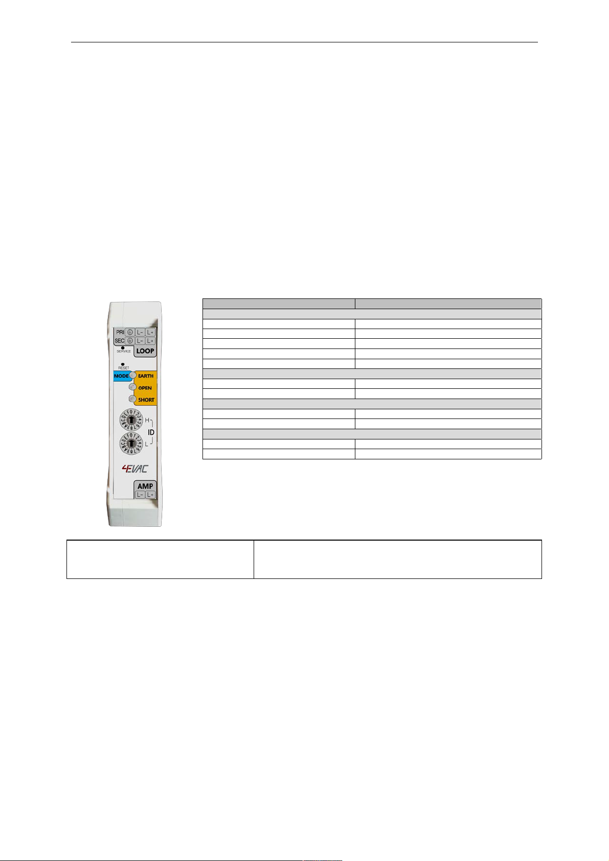
a. Fix LDB on a DIN rail and connect 24V/48VDC power supply to power terminals on 5-pin rail connector. LDB
should boot-up, indicating boot progress with blue blinking on MODE indicator
b. Within 15 seconds LDB will indicate OPEN fault, since AMP input as well as both LOOP outputs are not
connected.
c. Connect output of power amplifier to the AMP input of LDB. LDB is not sensitive for amplifier output
polarity, however it is recommended to keep the correct polarity to maintain best acoustic coherence of
audio signal.
d. Connect the outgoing loop cable to PRIMARY output of LDB.
Note:
If any short circuit is present on the speaker cable, LDB will immediately detect and isolate the shorted connector and SHORT indication will
appear on LDB front panel. If the speaker cable connects to ground causing earth leakage, LDB will detect the earth leakage and EARTH
fault indication will appear on LDB front panel
.
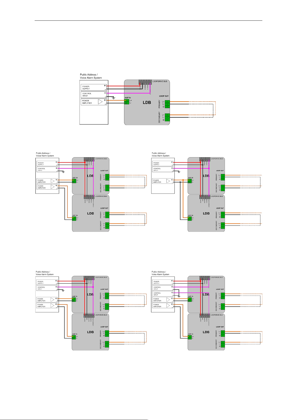
e. If system includes multiple loops (multiple LDBs), there is a number of ways you can interconnect Loopdrive
to the Public Address / Voice Alarm system.
Multiple LDBs can share common fault contact or individual fault control contacts of the main system. Fault
contact sharing allows you to reduce number of control inputs needed for fault reports. Detailed
information about the location and type of fault is always available on LDBs front panels, as well as via
Sniffer PC application.
Multiple LDBs can also share common power amplifier or have individual power amplifiers from the main
system. Amplifier sharing allows you to create multiple loops within one zone, each with individual
surveillance.

Loopdrive – User and installation manual
9
NOTE:
Loopdrive bus (DIN rail) interconnects multiple LDB units, supplying 24V/48V DC power, common fault contact output and RS485 serial bus.
Due to current limitation single bus can supply with 24V/48V up to 32 LDB units. Larger number of LDBs should be divided and fitted onto
separate power rails. Common RS485 bus and common fault output may be shared up to the maximum number of 256 LDBs in one system
Picture 2. Single LDB wiring
diagram
Picture 3. Multiple LDB wiring. Left: individual amplifier channels. Right: shared amplifier.
Picture 4. Multiple LDB wiring. Left: individual fault contact inputs. Right: common fault contact.

Loopdrive – User and installation manual
10
f. If you’re planning to proceed with installation of FIM modules on the loop, leave the SECONDARY output of
LDB disconnected. Go to next chapter for FIM installation instructions.
g. When loop is closed and all FIMs on the loop are working properly, connect the incoming loop cable to
SECONDARY output of LDB. Loop is now fully secured.
Picture 5. Complete Loopdrive installation d
ia
g
ra
m.
2.3. How to install FIMs on a loudspeaker line
Before you start connecting FIMs on the loop, make sure that LDB is connected to the rail and powered (see previous
chapter).
a. For most efficient installation make sure that LDB is in SERVICE MODE (blue MODE indicator blinking fast).
To put LDB into SERVICE MODE press SERVICE button for 10 seconds or use Sniffer PC application.
b. During SERVICE MODE LDB will show OPEN fault indication as long as the loop is not completely closed.
This is the correct indication, since the loop should be closed only at the final stage of installation, to make
sure that the entire course of the loop is complete.
NOTE:
When Loopdrive is in SERVICE MODE, audio signal from power amplifier is not transmitted to the loop.
c. Double check if the loudspeaker line cable is connected to the PRIMARY loop output of LDB and the
SECONDARY loop output of LDB is not connected.
d. LDB should indicate only OPEN fault. If SHORT fault is detected, fix it before FIM installation
e. Check if EOL switch on the FIM is in OFF position.
NOTE:
EOL switch should be in ON position only with EOL resistor connected to the termination of T-Branch line. Short circuits on T-Branch are
detected and isolated regardless the EOL monitoring switch.
f. Connect FIM to the loop cable on the PRIMARY side of LDB. Mind the cable polarity!
NOTE:
You can connect the loop cable to either A or B side of FIM, both sides are equal. Do not connect loop cable to T-Branch connector!
g. FIM will power up indicating charging process (blue slow blinking). Wait for FIM to enter SERVICE MODE
(blue fast blinking).
NOTE:
Brand new FIMs are delivered in FACTORY RESET state. In this state loop relays on FIM’s PCB should be in open position. FACTORY
RESET state for FIM is temporary. Soon after power up FIM should switch relays to closed position, making a “click” sound, confirming
correct relay operation.

Loopdrive – User and installation manual
11
Picture 6. Side A of FIM connected to PRIMARY side of the
l
oo
p
.
h. Connect the outgoing loop cable to the loop connector on the other side of FIM. Mind the cable polarity!
i. If the cabling is correct, FIM will remain in SERVICE MODE.
If there’s short circuit on the outgoing cable, FIM will change blinking colour to orange, indicating problem.
LDB will also detect short circuit and indicate it with SHORT indicator. Fix the cabling before further
installation.
Picture 7. Both sides of FIM properly connected to the
l
oo
p
.
j. If needed, connect the loudspeaker or T-Branch line to FIM T-Branch connector.
In case of short circuit on T-Branch, FIM will indicate the problem with orange alternating blinking (see
indications table).
Picture 8. Single loudspeaker connected to T-Branch
connector
.
k. If EOL resistor is installed on the end of T-Branch line, switch the EOL monitoring ON. In case of T-Branch
line open, FIM will indicate the problem with interrupted orange alternating blinking (see indications table).
l. If the T-Branch cabling is correct, FIM will remain in SERVICE MODE.

Loopdrive – User and installation manual
12
Picture 9. T-Branch line with EOL monitoring.
m. Proceed with installation of the next FIM module.
n. When the last FIM is installed on loop go back to the LDB and connect the returning loop cable to
SECONDARY output connector of LDB.
If cable loop is complete and works correctly, OPEN indication on LDB will stop, LDB remains in SERVICE
MODE.
o. Reset LDB by pushing RESET button. LDB will reboot to QUIESCENT MODE.
Picture 10. Complete Loopdrive installation diagram.
Picture 11. Complete Loopdrive installation - with optional GROUND wire loop.

Loopdrive – User and installation manual
13
2.4. Examples of Loopdrive installations
Picture 12. Minimum configuration - equivalent to A/B line.
Picture 13. Speakers only on the loop.
Picture 14. One FIM per each speaker.

Loopdrive – User and installation manual
14
Picture 15. T-Branch lines with multiple loudspeakers.
Picture 16. Mixed
c
onf
i
g
urati
on.
3. Routine maintenance inspection
In order to check correct Loopdrive operation in case of potential cabling failure, simulate faults and observe system
reaction. Perform following procedure:
a. Check if LDB is powered
b. If LDB is indicating FAULT mode (orange LED blinking) go to chapter “Faults”.
Continue to next steps only if LDB is indicating QUIESCENT mode.
c. Put LDB into SERVICE MODE (press SERVICE button for 10 seconds)
d. Simulate short-circuit fault
1. Using a jumper make direct short between L+ and L- wire on PRIMARY or SECONDARY output of LDB.
2. Confirm that SHORT indication on LDB appears.
3. Confirm that fault contact was activated.
4. Remove the short circuit. Confirm that SHORT indication on LDB disappears.
e. Simulate open loop fault
1. Disconnect loop cable from PRIMARY or SECONDARY output of LDB.
2. Confirm that OPEN indication on LDB appears.
3. Confirm that fault contact was activated.
4. Connect the loop cable back to LDB. Confirm that OPEN indication on LDB disappears.
f. Put LDB into QUIESCENT mode
g. Simulate earth leakage fault:
1. Make direct connection between L+ or L- wire to ground potential (Ground pin of LDB)
2. Confirm that EARTH indication on LDB appears.

Loopdrive – User and installation manual
15
3. Confirm that fault contact was activated.
4. Remove the connection between L+ or L- to earth.
5. Confirm that EARTH “active” (fast) indication on LDB turns into “memory” (slow).
6. Reset LDB into QUIESCENT mode.
h. Simulate ground wire open fault
(opti
ona
l)
1.
Open ground wire on PRIMARY or SECONDARY output of LDB.
2.
Confirm that EARTH indication on LDB appears.
3.
Confirm that fault contact was activated.
4.
Connect ground wire back to LDB.
5.
Confirm that EARTH “active” (fast) indication on LDB turns into “memory” (slow).
6.
Reset LDB into QUIESCENT mode.
i.
Ch
eck cables and connectors between LDB and Public Address / Voice Alarm system.
4. Fault finding – LDB
The effort and time spent of finding and fixing loudspeaker line faults with Loopdrive system is reduced to minimum.
Loopdrive is designed to locate and report the exact location of fault, even long time after its occurrence. You can
repeat fault finding procedures multiple times, any time you want, making sure that repair works will be efficient and
accurate.
Finding a loudspeaker line fault usually starts at the main system rack, where LDB units are located. Observe LDB
front panels and compare the indications to indication table in this manual.
NOTE:
Multiple faults can be shown on LDB at same time. SHORT, OPEN and EARTH fault may be detected and indicated simultaneously and
should be investigated individually
.
If fault indications on LDB are in “memory” state (slow blinking), simply push RESET button on LDB and after reboot
LDB will return to QUIESCENT mode.
Following information relates to situation where there is an active fault indicated. More details you’ll find in LDB
indications table (Table 1.) in chapter 1.
4.1. SHORT fault
LDB shows SHORT fault in following cases:
a. Short circuit on the loop, between FIM modules
In this case Short fault is located in the field, not directly at LDB connector. FIM modules are isolating faulty
section of the cable, so the loop stays open until the short circuit is removed. In this state reset of LDB will
clear the SHORT indication and LDB will detect loop open fault, indicating OPEN active.
b. Short circuit on the PRIMARY or SECONDARY port of LDB
In this case short circuit is located adjacent to LDB, therefore LDB detects the fault directly and any attempt
to reset LDB brings no result – LDB returns to SHORT active state.

Loopdrive – User and installation manual
16
c. Single (or odd number) twist in loudspeaker cable polarity
If cabling polarity is mismatched in one place in your installation (or more but odd number), Loopdrive will
react with SHORT indication.
What to do?
Reset LDB and observe the following indication:
a. If LDB returns to SHORT active indication, short circuit is located on the cable section directly connected to
PRIMARY or SECONDARY.
b. If LDB turns to OPEN active indication, short circuit is located on the loop in the field. You need to take
further steps to locate the faulty section. Two alternative solutions are available:
a. 4EVAC Loopdrive Sniffer (PC application) is the easiest way to go. Use FIM tracking feature for the best
result. FIM tracking is automated procedure which allows you to find the exact location of the short
fault. Please, go to the Loopdrive Sniffer manual for details.
b. Disconnect loudspeaker cable from SECONDARY output of LDB and put an audio signal in the zone
including faulty loop. Loopdrive will feed the loop with audio signal only from PRIMARY side. While
listening to loudspeakers follow the loop and find first area with no sound reproduction. This area is
isolated from the loop because of the fault. To find the end of isolated section, connect the SECONARY
side back to LDB and find the first area with sound reproduction.

Loopdrive – User and installation manual
17
4.2. OPEN fault
LDB shows OPEN fault in following cases:
a. Loop cable is open (L+ or L- or both wires)
b. Loop section between FIMs is isolated because of previously detected short circuit. See previous chapter:
SHORT indication.
c. T-Branch fault (OPEN or SHORT)
NOTE:
In case of T-Branch fault (OPEN or SHORT), FIM will open both loop relays, isolating T-Branch and causing the loop OPEN fault on LDB. The FIM
reporting T-Branch fault will stay open until the fault is still detected. To close the loop again, FIM reset is required after removing the fault.
d. Power amplifier is disconnected.
What to do?
First: check if power amplifier is connected. If so, continue with the same procedure as for SHORT fault. Two
alternative solutions are available:
a. Loopdrive Sniffer (PC application) is the easiest way to go. Use FIM tracking feature for the best result.
FIM tracking is automated procedure which allows you to find the exact location of the open fault.
Please, go to the Loopdrive Sniffer manual for details.
b. Disconnect loudspeaker cable from SECONDARY output of LDB and put an audio signal in the zone
including faulty loop. Loopdrive will feed the loop with audio signal only from PRIMARY side. While
listening to loudspeakers follow the loop and find first area (including T-Branches) with no sound
reproduction.
4.3. EARTH fault
LDB reports EARTH fault if any cable in the line (including T-Branch lines) causes a current leakage to the ground.

Loopdrive – User and installation manual
18
What to do?
To find earth leakage in your installation, please use the FIM tracking feature of Loopdrive Sniffer PC application. FIM
tracking is automated procedure which allows you to find the exact location of the earth fault. Find more details
i
n th
e
Sniffer manual.
4.4. Wrong cable polarity – double twist
If there are two (or more but even number) twists in loop cable polarity, some of FIM modules are not powered and
therefore system is not fully operational. Loopdrive however will not detect any fault and will act normally, as if the
loop was correct.
What to do?
To find double twists in your installation, please use the FIM tracking feature of Loopdrive Sniffer PC application. FIM
tracking allows you to automatically count the number of FIM modules on the loop. Find more details in the Sniffer
manual.

Loopdrive – User and installation manual
19
5. Fault finding – FIM
Next step after identifying a fault on LDB is to investigate and fix the cabling in the field. Indication on FIM will help
you finding the exact location and type of the fault.
NOTE:
Multiple faults can be shown on FIM at the same time. In this case different fault indications will be superimposed, creating combined
indication. FIM can be reset only if all faults are removed and all indications are in “memory” state
If fault indications on FIM are in “memory” state (slow orange blinking), simply push RESET button on FIM (or send
REMOTE FIM RESET command from LDB) and after reboot FIM will return to QUIESCENT mode.
Following information relates to situation where there is an active fault indicated. More details you’ll find in FIM
indications table (Table 4. and Table 3.) in chapter 1.
5.1. Short loop
If loop is shorted on either of the sections connected directly to FIM, the LED indicator on the faulty section side will
blink orange fast. FIM is isolating the faulty section with open relay. T-Branch is still operational and fed with audio
from the healthy side of the loop.
Picture 17. Short on side A Picture 18. Short on side
B.
What to do?
Remove the short-circuit from the loop section. When the problem is fixed, the fast blinking indication on FIM will
turn slow. Now you can reset FIM to QUIESCENT mode, where both A and B relays are closed. To reset FIM:
a) push RESET button on the FIM module
or
b) send REMOTE FIM RESET command by pressing RESET button on LDB for 10 seconds or via Sniffer
application.
5.2. Short on T-Branch
If T-Branch is shorted, both A and B indicators will blink fast orange alternately. Both relays of the FIM are open,
creating an interruption in the loop. T-Branch is isolated from the loop.
Picture 19. Short on
T-Bra
n
c
h
What to do?
Remove the short-circuit from the T-Branch. When the problem is fixed, the fast blinking indication on FIM will turn
slow. Now you can reset FIM to QUIESCENT mode, where both A and B relays are closed. To reset FIM:
This manual suits for next models
1
Table of contents
Other 4EVAC Safety Equipment manuals
Popular Safety Equipment manuals by other brands

Pilz
Pilz PNOZ e1.1p operating instructions

Amplicon Liveline
Amplicon Liveline 232i9 quick start guide

deconta
deconta decontamination mobile D 3000 Guide book

Kaya Safety
Kaya Safety Rock RAWL-1 user guide

SafeWaze
SafeWaze FS-EX213 Operation and instruction manual

Reliance
Reliance Skyloc 4 Series Instructions for use