4EVAC IMPACT User manual

Hacousto Holland bv
Industrieweg 87
2651BC Berkel & Rodenrijs
CONTROLLER user manual
Author:
DD
Page 1 of 14
SUMMARY
This document is the user and installation manual of the 4EVAC Controller, the head unit of the 4EVAC
Impact voice evacuation system.
REVISION AND APPROVAL
Rev.%
Date%
Nature%of%Changes%
Approved%By%
01%
05-06-2019%
Original%draft%
DD%
02%
10-03-2020%
Updated%CAL%button,%GPO%rating,%#%of%zones,%net%ports,%
max.%output%power,%#%of%DCA%amplifiers,%%#%of%messages%
DD%
03%
08-06-2020%
Corrections%
TvdH%
04%
11-06-2020%
Minor%corrections%
DD%

Hacousto Holland bv
Industrieweg 87
2651BC Berkel & Rodenrijs
CONTROLLER user manual
Author:
DD
Page 2 of 14
Table of Contents
1.!General information ............................................................................................................................................................. 3!
2.!Front indicators ...................................................................................................................................................................... 3!
!POWER ........................................................................................................................................................................... 3!
!EVAC ................................................................................................................................................................................ 4!
!GENERAL FAULT .......................................................................................................................................................... 4!
!POWER SUPPLY FAULT ............................................................................................................................................. 4!
!SYSTEM FAULT ............................................................................................................................................................. 4!
!NETWORK FAULT ........................................................................................................................................................ 5!
3.!Front buttons .......................................................................................................................................................................... 5!
!SILENCE .......................................................................................................................................................................... 5!
!LAMP TEST .................................................................................................................................................................... 5!
!EVAC ................................................................................................................................................................................ 5!
!ALERT .............................................................................................................................................................................. 5!
!RESET ............................................................................................................................................................................... 5!
4.!Back panel ............................................................................................................................................................................... 6!
!Analog audio inputs ................................................................................................................................................... 6!
!AMP LINK ....................................................................................................................................................................... 6!
!Local network ................................................................................................................................................................ 7!
!Global network ............................................................................................................................................................. 8!
!Ethernet (option) ......................................................................................................................................................... 9!
!Device ID ........................................................................................................................................................................ 9!
!Micro SD card ............................................................................................................................................................... 9!
!CAL button .................................................................................................................................................................... 9!
!RESET button ................................................................................................................................................................ 9!
!GPO ................................................................................................................................................................................. 9!
!Relay outputs ............................................................................................................................................................... 10!
4.11.1.!EVAC ................................................................................................................................................................. 10!
4.11.2.!FAULT ..................................................................................................................................................... 10!
4.11.3.!RESET ...................................................................................................................................................... 10!
4.11.4.!USR DEF ................................................................................................................................................. 10!
!EVAC inputs ................................................................................................................................................................. 10!
5.!Connections and recommended cable types ............................................................................................................. 11!
6.!Technical specifications ...................................................................................................................................................... 12!

Hacousto Holland bv
Industrieweg 87
2651BC Berkel & Rodenrijs
CONTROLLER user manual
Author:
DD
Page 3 of 14
Thank you for choosing 4EVAC as your Voice Evacuation System solution.
4EVAC Impact is a 19” rack format, EN54-16 certified Voice Evacuation System, dedicated to medium to
large installations. The Impact system is capable of both standalone and network operation, for a wide
selection of peripheral devices and remote extensions. 4EVAC Impact is certified in accordance with EN54-
16 and EN54-4, which are harmonized standards under the Construction Products Regulation, mandatory
in the European Union.
The 4EVAC Impact system is fully compatible with the Compact 500 Voice Evacuation System. This means
that both systems can be connected to one network, running the same protocol in peer-to-peer
architecture, operating within the same space of voice evacuation zones, sharing the same audio messages,
BGM broadcasts, microphone consoles, I/O extensions and cabling infrastructure.
1.
General information
4EVAC Controller is the head unit of the 19” rack mounted Impact Voice Evacuation System. The Controller
covers complete EN54-16 certified functionality, as well as a variety of features essential to Public Address
applications.
4EVAC Controller incorporates 16 monitored contact inputs; 8 GPO, 4 relay outputs, 2 analogue audio
inputs and 2 outputs. In addition, local network interfaces for max. 16 local peripheral devices (e.g. mic
consoles) and 2 global network ports for interconnecting multiple systems in a redundant ring topology
are included.
The Controller is designed to work with 4EVAC DCA2.500 power amplifiers over a 4EVAC proprietary AMP
LINK protocol. The Controller can also be easily integrated with any third-party PA/VA power amplifier.
2.
Front indicators
POWER
Indicates if the Controller is being powered and if the system is properly booted.
OFF
Not powered
GREEN continuous
This device is powered and operational.
GREEN blinking
This device is booting after power up / reset.

Hacousto Holland bv
Industrieweg 87
2651BC Berkel & Rodenrijs
CONTROLLER user manual
Author:
DD
Page 4 of 14
EVAC
Indicates that the system is in the Voice Alarm state, where at least one zone in the system is occupied by
an emergency audio signal, i.e. a pre-recorded EVAC MESSAGE or LIVE EVAC, when a fireman mic is being
used.
OFF
EVAC status is inactive (quiescent mode)
RED continuous
EVAC status is active
GENERAL FAULT
Indicates that the system is in the FAULT state (general fault indicator), where at least one device in the
system is reporting a fault.
OFF
System is healthy
YELLOW continuous
Local fault is detected
(failure of Impact controller or local AMP LINK amplifiers)
YELLOW blinking
Remote fault is detected
(this Impact controller and amplifiers are healthy and another device in the
network is reporting fault state)
POWER SUPPLY FAULT
Indicates a power supply fault of the local Impact system, where at least one of following faults is reported
OFF
Power supply OK
YELLOW blinking
Battery-related fault:
o Loss of battery
o Loss of charger
o Battery resistance too high
o Temperature fault
YELLOW continuous
Mains fault
SYSTEM FAULT
Indicates a system fault of the Impact Controller, where:
- a CPU or program execution is stopped or malfunctioning,
- there is a corruption of storage memory containing config settings and audio files (SD card).
Where the system fault is caused by a CPU or memory fault, the Controller remains in its “safe state”, where
critical functions (including audio transmission, reaction on control inputs, etc.) are stopped until the fault
is resolved.
OFF
Firmware and settings OK
YELLOW continuous
CPU / program fault

Hacousto Holland bv
Industrieweg 87
2651BC Berkel & Rodenrijs
CONTROLLER user manual
Author:
DD
Page 5 of 14
YELLOW blinking
o SD card fault
o Config file not compatible
o Wrong ID setting
NETWORK FAULT
Indicates when any device or link in the network is missing.
OFF
Network OK
YELLOW continuous
At least one device from the network is missing.
YELLOW blinking slow
Global ring is broken (any place in the ring)
3.
Front buttons
SILENCE
Press to mute the sound of the buzzer in the entire system.
LAMP TEST
Press to verify visual (LEDs) and audible indications (buzzer) of the front panel of the local Controller and
local amplifiers (connected to AMP LINK of local Controller).
EVAC
Press to trigger the EVAC message in all zones in the entire system.
ALERT
Press to trigger the ALERT message in all zones in the entire system.
RESET
Press to reboot the system. In a network system this will reboot the entire network.
NOTE: Applying RESET will re-initiate AMP LINK and re-assign addresses and settings of amplifiers
connected to the AMP LINK, according to the configuration settings of the Controller. Addressing of the
amplifiers follows the order of the AMP LINK physical connection (see chapter “AMP LINK”).

Hacousto Holland bv
Industrieweg 87
2651BC Berkel & Rodenrijs
CONTROLLER user manual
Author:
DD
Page 6 of 14
4.
Back panel
Analog audio inputs
In the left section the Controller provides 2 independent analogue audio inputs dedicated for BGM
broadcast.
2 x mono, balanced, line level (0dbU / 0.775Vrms), 15kΩ input impedance.
Connect your auxiliary audio source for background music or low priority external paging microphone here.
AMP LINK
The AMP LINK (RED vertical cat5 cable) is the secured bus connecting the Impact
Controller to up to 16 x DCA2.500 amplifiers. Based on RS485, this internal system
bus provides:
- 2 balanced audio channels across the entire AMP LINK chain, monitored;
- Control and diagnostics data interface.
In order to work properly, the AMP LINK must be set up in the configuration settings
(“Amplifier” tab).
Amplifiers connected to the AMP-LINK are addressed and initiated by the Controller
at each system reboot.
NOTE: Reboot the system (Controller front panel RESET) after each modification
applied to any amplifier on the AMP-LINK, including:
-
replacing / adding / removing a DCA2.500 amplifier (along with new configuration settings);
-
changing DIP-switch settings on DCA2.500 back panel;
-
replacing the battery;
24V DC input
(parallel connectors)
Analog audio
inputs
AMP LINK
Local network
ports
Global network
ports
Ethernet ports
Device ID
microSD
card
USB
CAL button
(not used)
Reset
button
GPO
Relay outputs
EVAC inputs

Hacousto Holland bv
Industrieweg 87
2651BC Berkel & Rodenrijs
CONTROLLER user manual
Author:
DD
Page 7 of 14
The AMP-LINK is monitored but not redundant. Therefore, in order to maintain EN54 – IP30 compliance,
the AMP-LINK cable must not be exposed to external field influences and remain fully protected and closed
entirely inside the cabinet of the Impact system.
Amplifiers connected to the AMP-LINK are addressed (numbered) in the same order as they are physically
connected to the controller via an AMP-LINK cable. In the configuration and diagnostic software
information “Amplifier 1” is the first unit on the bus (i.e. the closest and connected directly to the controller),
“Amplifier 2” is the second unit in the chain, etc.
AMP-LINK audio + data bus
Local network
The L-Net daisy-chain topology is dedicated to peripheral devices of the Controller, such as zone-expander
modules or remote microphone stations. The L-Net is used to expand functionality of the Impact system
to remote locations via a powered data bus. Every L-Net port is powered with 24V DC and power over L-
Net is always enabled.
The L-Net capacity of a single Compact 500 unit is limited to the following figures:
Maximum 8 devices per port,
Maximum 16 devices per Controller.

Hacousto Holland bv
Industrieweg 87
2651BC Berkel & Rodenrijs
CONTROLLER user manual
Author:
DD
Page 8 of 14
L-Net daisy chain topology
The L-Net port delivers power to remote devices. The maximum power capacity of each L-Net port is
500mA (protected with a, slow type, automatic fuse). L-Net devices of different types have different average
power consumption, which may vary from 30mA up to 180mA. This implies limitations in terms of the
maximum number of devices powered over the L-Net.
NOTE: Consider power consumption of L-Net powered devices!
In the table below, you can see an example of power consumption over the L-Net. This example showcases
the usage of a single type of L-Net device (4E-FMTC microphone console with 180mA current consumption
@24V), where the units are distributed equally over the L-Net cable.
No. of
devices
on single
L-Net bus
Maximum total L-Net cable length
Method of Power
Total current draw
@24V
AWG26
(13.4ohms / 100m)
AWG24
(8.42ohms / 100m)
AWG22
(5.24ohms / 100m)
1
250m
250m
250m
From L-NET
180mA
2
186m
250m
250m
From L-NET
360mA
3
107m
170m
250m
Power injector
540mA
4
71m
113m
182m
Power injector
720mA
5
53m
85m
136m
Power injector
900mA
For more information about installation and powering of remote network devices, please see the network
device installation manual and 4EVAC Battery Calculator.
Note: Power injectors are available and can be found on our pricelist from May 2020.
Global network
G-Net is a redundant network ring where multiple Controllers may be connected into one system. It is used
to reliably synchronize data between all connected devices and for multi-channel live audio transmission
with very low latency. G-Net works as a redundant double ring between Controllers, which keeps the global
system intact in case of single link failure.
To create a redundant G-Net ring between multiple Controllers, connect both G-Net ports between every
unit in the network, so that you create a closed ring.
Power over G-Net (active by default) is dedicated to supply devices connected to the G-net port, such as
fiber transceivers (FSC).

Hacousto Holland bv
Industrieweg 87
2651BC Berkel & Rodenrijs
CONTROLLER user manual
Author:
DD
Page 9 of 14
Ethernet (option)
Interface to built-in dual port Ethernet switch (future expansion port for IP connectivity).
Device ID
The Controller is equipped with a rotary switch that determines the Device ID (or device address) in the
network. Make sure that the Device ID set on the rotary switch complies with the ID defined in the
configuration settings for this device.
Wrong ID setting will trigger a system fault because of a configuration error.
Micro SD card
The Controller is supplied with a pre-installed micro SD memory card. The memory card contains a
complete system configuration file, including audio messages.
The configuration file is prepared in the 4EVAC Manager – a Windows GUI application. More information
about creating configuration settings can be found in the 4EVAC Manager User Manual.
The memory card is under constant surveillance, as well as its contents. When the memory card is removed,
damaged or its contents are corrupted, the Controller will report a system fault. During a system fault,
caused by a memory error, it enters a safe state where the system stops all functions and requires a reboot.
This state can be reset only by a manual device reset.
CAL button
Firmware version 5.2 and up:
This button is not in use (AMP LINK is set up during system reboot, based on
configuration settings)
Firmware version below 5.2:
Press this button in order to calibrate the AMP LINK bus. Once calibrated, the
DCA2.500 amplifiers on the AMP LINK will communicate with the controller, exchanging information about
the power supply and amplifier status.
RESET button
Press to trigger a hard reset of the Controller (different from the RESET button on the front panel – soft
reset). This button will trigger a hardware reset of the local Controller only.
GPO
8 x general purpose output (open collector) with common ground.
GPOs are programmable in the configuration settings. The GPO can be linked to any system events to
follow system events and various zone states.
NOTE: Each output can accept max. 110mA and max. 24V open circuit voltage.

Hacousto Holland bv
Industrieweg 87
2651BC Berkel & Rodenrijs
CONTROLLER user manual
Author:
DD
Page 10 of 14
Relay outputs
The Controller features 4 potential-free relay outputs to external devices. Each output has individual 3 pins:
normally open,
normally closed,
common.
4.11.1.
EVAC
Activated (closed) during EVAC mode, where at least one zone of the voice evacuation system is
transmitting an automatic EVAC message or LIVE EVAC signal from a fireman microphone.
4.11.2.
FAULT
Activated (closed) while the fault status is reported by the voice evacuation system. Also activated when
the Controller is not powered.
4.11.3.
RESET
Activated (closed) immediately after a manual reboot of the system is triggered on the front panel. The
active pulse length of the reset signal is configurable from 0 (disabled) to 5000ms in the configuration
settings.
4.11.4.
USR DEF
This relay output is not in use.
EVAC inputs
There are 16 monitored inputs dedicated to triggering signals for evacuation, silence and reset instructions
from an external fire detection system, as well as any other events, including commercial activities.
Each of these inputs has 1 triggering pin, with a common ground level for all inputs. EVAC inputs have built-
in DC monitoring which requires two resistors of 4.7kΩ + 10kΩ in order to detect input active/inactive states
as well as short and open faults. The EOL resistors must be located directly at the triggering output inside
of the external device (i.e. fire detection system) to provide reliable surveillance of the entire link.
EVAC inputs must receive an activation signal of at least 100ms in order to trigger events. Pulses shorter
than 100ms will be ignored.

Hacousto Holland bv
Industrieweg 87
2651BC Berkel & Rodenrijs
CONTROLLER user manual
Author:
DD
Page 11 of 14
5.
Connections and recommended cable types
How
many
Connector
type
Signal type
Additional
information
Recommended cable
(minimum)
Max. length
Analog audio in
2
pluggable
screw
terminal
block
3.5 mm
Analog
balanced mono
audio, 0dBu
n/a
Balanced shielded
microphone cable, typ. 2
x 0.25mm2
100m
EVAC in
16
Pull-down input
with fault
detection
(open/short)
EOL resistors 10kΩ
+ 4.7kΩ in series
Depends on length, typ.
N x 0.75~1.5mm2 (N –
number of individual
triggering signals from /
to fire detection system)
1000m
EVAC / FAULT/
RESET out
3
Potential-free
relay output
n/a
1000m
GPI
8
Pull-down input
n/a
1000m
GPO
8
Open collector
output
max. 24V
max. 110mA
n/a
Depends on length, typ.
N x 0.75~1.5mm2 (N –
number of individual
triggering signals to
external devices)
1000m
AMP LINK port
1
RJ-45
Line level
analogue audio
+ RS485 data
UTP CAT5e
10m
G-Net port
2
Full duplex RS-
422
Redundant ring
with power
delivery
FTP CAT5e crossover
250m
(between
devices)
Power
limitations
apply
L-Net port
3
Daisy chain with
power delivery
DC Power in
1
Pluggable
screw
terminal
block
5.08mm
24~30V DC
n/a
2 x 1.5mm2
10m

Hacousto Holland bv
Industrieweg 87
2651BC Berkel & Rodenrijs
CONTROLLER user manual
Author:
DD
Page 12 of 14
6.
Technical specifications
Standalone system (single controller)
Number of zones
max. 96 local zones
Maximum total output power
16000 W
Dedicated power amplifiers
DCA2.500 2 x 500 W, max. 32 x 500W (max. 16 x DCA2.500)
Standby power amplifiers
500W per backup channel (configurable from 0 to 16 backup channels)
Loudspeaker line monitoring
SW6
20kHz AC monitoring with EOL module, short/open/impedance deviation
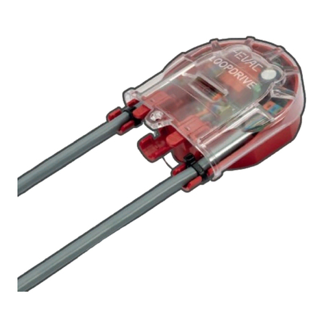
LOOPDRIVE
loop DC monitoring with short-circuit isolators, short/open/earth leakage,
EN54-17 certified
Voice messages
Storage
max. 22 audio files x 5 minute each, micro-SD card with content monitoring
Message player
Max. 2 simultaneous local message playback, priority control
Controls and indications
General controls / indications
Lamp test button, silence button, power, evac, general fault LED indicators
Fault indications
Power supply, system fault, network
Evac manual control
EVAC message, ALERT message, SILENCE, RESET
Power supply
PSE integrated within DCA2.500 (EN 54-4 certified)
DC supply input
24 – 30V DC (from DCA2.500)
Power consumption
140 mA @24V DC
Inputs
2 x BGM
2 x balanced analogue audio mono input, 0dBu, input impedance 15kΩ
16x EVAC in
monitored analogue inputs, 4.7kΩ +10kΩ EOL resistors
Outputs
EVAC out, FAULT out, RESET out
Potential-free relay output (configurable NO/NC) max. 1A
GPO
8 x Open collector output (configurable NO/NC) max. 24V / 110mA
Amplifiers (on AMP-LINK bus)
Type DCA2.500
Class D, transformer-less, direct output
PSE
integrated power supply equipment, EN54-4 certified
DC output
2A auxiliary purpose DC output
Charger
4A charger output, max. 100Ah (>80% in 24h according to EN54-4)
Protection
over load shutdown, over temperature shutdown
Backup amplifiers
auto backup at end stage failure, auto restore
Efficiency
96% @ rated power (DC-powered)
Output voltage
max. 100V RMS
Rated power
500W per channel
Bandwidth
50 Hz – 20 kHz
SNR
>80 dB
THD + N
<0.1% @ rated power
Audio
Frequency response
Local BGM
50 Hz – 20 kHz (AMP-LINK) uncompressed
Messages, network streaming
100 Hz – 12 kHz (G-NET) compressed
Analog input- output latency
< 10 ms (stand-alone system)
Network audio stream format
24 kHz sampling, ADPCM compressed
Message file input format
16 bit WAV, max. 5 minutes
DSP features
HP/LP filter, multipoint parametric EQ, input / output level
No. of output audio channels (AMP-LINK)
2

Hacousto Holland bv
Industrieweg 87
2651BC Berkel & Rodenrijs
CONTROLLER user manual
Author:
DD
Page 13 of 14
All information provided in this document is subject to change without notice. 4EVAC may also make improvements and/or changes
in the products described in this information at any time without notice.
Mechanical
Dimensions (HxWxD)
4.4 x 44 x 34 cm (1U)
Weight
4 kg
Housing material
Steel
IP rating
IP 30
Mounting
19” rack mounting
Operating conditions
Temperature (Ambient)
-5 ~ 40°C
Max. Temperature (Device)
65°C
Relative humidity
max. 90% (non condensing)
Storage temperature
-40 ~ 70°C
Network system
Max. number of devices in the network
254
Max. number of zones
254
Max. number of loudspeaker lines
1434
Max. total system output power
119.5 kW
Number of simultaneous network audio channels
2
Network audio transmission latency
0.3 ms per device
Local network
Architecture
Master-slave, up to 16 slave devices per Controller
Connection
3 x L-Net port, RJ-45, powered daisy chain, digital audio & control data
Cabling
X-over FTP CAT5e (or higher)
Current consumption
max. 500 mA per L-Net port
Max. length of local link (node-to-node)
default
250 m
with twisted-pair extenders
500 m
with MM fiber extenders
2500 m
Global network
Architecture
Peer-to-peer, up to 254 Controllers
Connection
2 x G-Net port, RJ-45, powered redundant ring, digital audio & control data
Cabling
X-over FTP CAT5e (or higher) / multimode optical fiber
Current consumption
max. 500 mA per port, reserved only for network extenders
Max. distance between devices
default
250 m
with twisted-pair extender
500 m
with MM fiber extenders
2500 m

Hacousto Holland bv
Industrieweg 87
2651BC Berkel & Rodenrijs
4EVAC Controller user and installation manual
Author:
DD
Page 14 of 14
MADE IN THE NETHERLANDS
4EVAC is a trade name of:
Hacousto Holland bv
Industrieweg 87
2651BC Berkel & Rodenrijs
The Netherlands
www.4EVAC.com
Other manuals for IMPACT
2
Table of contents
Other 4EVAC Safety Equipment manuals
Popular Safety Equipment manuals by other brands

KStrong
KStrong Kapture Element Hotworx User instruction manual

D+H
D+H RZN 4503-T troubleshooting guide

Petzl
Petzl EVOLV ADJUST L35 manual

CMC Rescue
CMC Rescue ProSeries Litter Harness quick start guide

SKYLOTEC
SKYLOTEC RAPTOR C20 Instructions for use

HABERKORN
HABERKORN euroline Tree Austria 3.2 INSTRUCTIONS FOR USE AND TEST MANUAL

SHENZHEN FANHAI SANJIANG ELECTRONICS
SHENZHEN FANHAI SANJIANG ELECTRONICS A9060T instruction manual

Force
Force P-35 instruction manual

Petzl
Petzl KOOTENAY TECHNICAL NOTICE

Super Anchor Safety
Super Anchor Safety Quick-Strap instruction manual

Maxair
Maxair 2099-14 User instructions

KRATOS SAFETY
KRATOS SAFETY FA 10 901 00 operating instructions